Active Tracking in Mobile Networks: An In-depth View Michal Ficeka,∗, Tomáš Popb , Lukáš Kencla a Czech
Technical University in Prague, Faculty of Electrical Engineering, Department of Telecommunication Engineering, Technická 2, 166 27 Prague 6, Czech Republic b Charles University, Faculty of Mathematics and Physics, Department of Distributed and Dependable Systems, Malostranské námˇ estí 25, 118 00 Prague 1, Czech Republic
Abstract Tracking of mobile terminals in mobile networks is a technology with growing and diverse applicability. However, this task is non-trivial and might require either terminal or network adjustment and cooperation. Flexible, scalable, and cost-effective means of network-based tracking are highly desirable from the perspective of mobile operators. We present an in-depth overview of a particular method, the SMS-based active tracking, and demonstrate how this lean and non-intrusive approach is applicable to various existing architectures of mobile networks. We show the practicality of this approach by describing our academic proof-of-concept implementation, capable of tracking thousands of users periodically on the scale of minutes. We analyze the limits of active tracking, posed by the various network and terminal constraints (such as connection throughput, mobile network capacity or terminal battery lifetime) and conclude with discussion of its wide and long-term applicability. Keywords: mobile network, active tracking, mobility, positioning, GSM, Cell-ID
1. Introduction Mobile Location Based Services (LBSs) have been growing rapidly over the past years [1] and market forecasts indicate similar growth in the near future [2]. Services such as navigation [3], local search [4], buddy finder [5], location sharing [6], and many others [1], represent an unprecedented new way to give consumers added value for carrying their mobile terminals. Along with these LBSs focused on the end user, important services for governments or network operators are feasible within a mobile network: tracking suspects and offenders [7], tracking residents and tourists to deliver urban studies [8], or tracking mobile users for network diagnostics [8, 9]. These tracking services are beneficial for specific applications, bringing the ability to analyze trajectories and location patterns over time in fine detail. However, they make specific demands on the mobile terminal positioning technology: it must be able to determine the position of an arbitrary network user (even a ∗ Corresponding author. Tel.: +420 606 842 803; fax: +420 233 335 999. Email addresses:
[email protected] (Michal Ficek),
[email protected] (Tomáš Pop),
[email protected] (Lukáš Kencl)
Preprint submitted to Computer Networks
non-cooperating or an idling one) with an arbitrary terminal (the latest model or an older one), and it should locate the terminal inside buildings, in a city, or in the countryside. Furthermore, periodic positioning is also more technologically challenging and places additional demands on network capacity. A plethora of different positioning methods are available nowadays [10]. These include terminal-based solutions, relying on dedicated hardware or software on the mobile terminal, network-based solutions, for which a network upgrade is necessary, combinations of both, referred to as hybrid solutions, or methods delivered by third parties who utilize both the terminal and other parties’ network infrastructures. Among these methods, however, it is hard to find an alternative for mobilenetwork operators who would like to enrich their service portfolio with a scalable tracking ability without major updates to the mobile network infrastructure and capacity, i.e., with a non-intrusive and low-overhead solution. These limitations are of particular interest in developing regions, where cost-effectiveness is a major factor when deploying new services over legacy networks. Our work focuses on a lean, cheap, and networktechnology independent tracking solution that does February 26, 2013
not require any software or hardware changes within the core network elements and that can locate any type of mobile terminal. The demands above exclude all terminal-based positioning techniques, including the popular A-GPS (Assisted Global Positioning System) [11], as they need dedicated hardware or software in the mobile terminal. With rapidly growing diversification among mobile phones, a universally applicable terminal-based solution requires permanent software updates over a range of platforms, and this is an increasingly costly and demanding task. Tracking may be ensured for smartphones by exploiting a permanent mobile data connection, where each data packet received provides up-to-date location in the network. However, while the segment of smartphones is rapidly growing, globally it is still a significant minority and sending data packets periodically has major negative impact on the device battery [12]. Thus, network-based approach to positioning is highly beneficial. Recent surveys of positioning methods in mobile networks [10, 13] indicate that only a few network-based methods have no significant impact on the mobile terminal: Cell-ID positioning [4], which derives the location of a user from the coordinates of the serving cell, and the U-TDoA (Uplink Time Difference of Arrival) method [14], which computes the terminal’s position based on hyperbolic lateration and the time it takes a signal to travel from a mobile phone to the network base stations. Compared to the Cell-ID positioning, the U-TDoA method is more accurate, but is generally slower and more demanding. Furthermore, the U-TDoA method needs special hardware to be installed in a substantial number of network base stations, which brings huge costs associated with the massive upgrade to the network infrastructure. CellID positioning can thus be considered as the more appropriate solution for tracking applications.
existing solution, and a justification for why the other ordinarily used positioning methods are not advisable to these tasks (Section 2). Such services include tracking suspects and offenders, tracking tourists (see an example in Figure 1), and tracking mobile users for network diagnostics. • We describe how network-based active tracking works in general and then provide an in-depth view of a particular method, the active SMS-based tracking, for which we show how this lean and non-intrusive approach is applicable to various existing architectures of mobile networks (Section 3). • We demonstrate the practicality of the approach by describing our academic proof-of-concept implementation of network-based active tracking running in a live GSM network and tracking thousands of network users simultaneously (Section 4). • We theoretically determine the fundamental limits of SMS-based active tracking and validate those empirically with measurements of the baseline implementation (Section 5), and outline how these limiting factors can be avoided or at least moderated. In summary, this paper demonstrates the usefulness of active tracking in mobile networks and presents an effective alternative for its implementation. This work builds on material presented in papers [8] and [16], yet it is self-contained and put into the broader context of location tracking and positioning in mobile networks. 2. Location Tracking and Positioning in Mobile Networks This section provides a comparison of positioning methods in mobile networks with respect to the use of mobile terminal tracking. The evaluation is based on
In this work we focus on a particular type of networkbased active tracking that uses Cell-ID positioning — the SMS-based tracking. This tracking method is unique because of the minimal effort and costs necessary to integrate it into the existing infrastructure of any of today’s widely used mobile network architectures, such as GSM, UMTS, or LTE, since it utilizes only the most basic network services. Its active nature, which means that users’ positions are pro-actively and frequently requested by the network, delivers several-times more accurate positions than passive tracking which contains only the position of the users’ last voice or text message communication [15]. Our contributions are as follows:
Figure 1: Network-based active tracking use example: places in the Czech Republic visited by a sample group of tourists — spatial interpolation of the numbers of tourists that visited each discrete cell. Source: [8].
• We identify a broad class of LBSs, where networkbased active tracking represents undoubtedly the best 2
accuracy, availability, roll-out costs, and other criteria. We show that only the network-based active tracking method is a viable solution to enable a broad range of location tracking services when low-cost implementation and support for all mobile terminals are preferred.
user’s position on the order of hundreds of meters is good enough for country-wide applications; for network coverage diagnostics the user’s network footprint, i.e., cell association, suffices. Besides, a rough estimate of a mobile terminal position may in fact help to partially anonymize the user’s location data by aggregating the positions on a network-cell level, though limited with time domain exposure [21]. C2: Costs. The roll-out costs of a positioning method, i.e., the price to install a new infrastructure or to extend an existing one, represent an important criterion on the basis of which the positioning method is often selected without reference to other parameters. In the rest of this section we compare positioning methods in mobile networks with respect to the requirements R1–R4 and criteria C1–C2.
2.1. Location Tracking Service We consider the problem of simultaneously tracking a number of mobile network users or, more specifically, their mobile terminals. By tracking we mean collecting continuous information on the user’s geographical position. Thus, some positioning method in the mobile network must be utilized to periodically deliver the position of the user’s terminal in the mobile network. Not to limit the range of application scenarios, we assume that the positioning method meets the following requirements: R1: Terminal independent. Since there is a large diversity in the recent mobile terminal market, we do not rely upon the user’s terminal type, manufacturer, or its software or hardware equipment. R2: Availability. The method must be able to deliver the mobile terminal’s position in all environments (indoor, rural, urban); thus preferably always when on signal. R3: Latency. The method must enable request repetition within a reasonably short time interval (on the order of seconds) with an overhead low enough to allow a large number of terminals to be positioned simultaneously. R4: Communication independent. We do not assume anything about the mode of a user’s communication — the tracking method must be able to obtain a user’s position even when they are idling, i.e., not actively communicating by voice, text message, or data means. The requirements we impose on the positioning method are not artificial ones — there are numerous services that take advantage of them and, in fact, could not even operate without them. The applications of that kind are, for example, for tracking suspects and offenders [7], mobility and human activity research [8, 17], mobile network user tracking for signal coverage diagnostics [8] or roaming optimization [18]. In general, requirements R1–R4 pose the advantage of tracking mobile network users even without their consent (criminals) or without burdening them (tourists, ordinary network users). However one has to keep in mind all consequential privacy concerns and legal aspects [19, 20]. The two following criteria certainly influence the selection of a positioning method: C1: Accuracy. The level of positioning accuracy may not be a concern — for some cases the approximate
2.2. Positioning Methods in Mobile Networks Existing positioning methods in mobile networks can be classified as network-based or terminal-based, depending on the site that performs measurements and calculates the position. A hybrid approach, called terminal-assisted, is possible when the measurements are made by the terminal and the position is calculated by the network. 2.2.1. Terminal-based Positioning Terminal-based positioning techniques [22, 23] achieve good accuracy, but require special hardware or software in the terminal and usually rely on external satellite infrastructure. The best known representative is Global Positioning System (GPS), which provides high accuracy but poor availability (as observed by Smith [23]), mainly because GPS does not work inside buildings. Assisted-GPS (A-GPS), a hybrid solution, utilizes additional assistance information from the mobile network which leads to shorter time to fix the first position of the terminal. Moreover, it provides even better accuracy than GPS and increases receiver sensitivity. Whereas terminal-based solutions tend to be less limiting for evolving mobile devices (smartphones), smartphone share is still only 29% globally [24] and varies widely among different countries. This prevents universal coverage. 2.2.2. Terminal-assisted Positioning Terminal-assisted positioning methods, such as Enhanced Observed Time Difference (E-OTD) [26] in GSM networks or Observed Time Difference of Arrival (OTDoA) [27] in UMTS networks, work on a lateration principle explained as follows. For circular lateration, 3
ing needed and face the trade-off between positioning accuracy and implementation costs. The first representative, Uplink Difference of Arrival (U-TDoA) [14, 30], is based on hyperbolic lateration similar to the terminal-assisted E-OTD method. But conversely to it, the time measurements are applied in the uplink, which means that the signal emitted from a terminal is observed by the network. The obvious advantage of such an approach is that an arbitrary mobile terminal may be located in the network. An essential prerequisite to observing a signal emitted from a terminal is that the terminal must be in busy mode, which means being in an ongoing connection with a base station. To overcome this and perform positioning of an idle terminal, the network must force the terminal to transmit data, which brings the network additional overhead. Just as for the E-OTD method, the network has to be equipped with LMUs. The Cell-ID method, often referred to as Cell Identification or Proximity Sensing, is another example of network-based positioning. It represents the easiest way to report the position of a mobile terminal. Cell-ID positioning relies on the fact that the mobile terminal can be attached to only a single cell at a time. Thus, if the network identifies the current cell the terminal is attached to, and location of the base station on which the transceiver forming the cell is deployed is known, the approximate position of the mobile terminal is then reported as the coordinates of the base station, or a centroid of the shape of the cell as shown in Figure 2, terminal C. Since the mobile terminal can be located anywhere within the cell, the accuracy of the reported position depends on the cell size, which varies from hundreds of meters in urban areas to several kilometers in rural areas. On the other hand, Cell-ID positioning does not require any dedicated functionality in the mobile terminal and thus works with any mobile terminal. Besides, no update to the mobile network is needed except for a simple signaling functionality and the CellID mapping database, which both are present in the network anyway. The poor accuracy of Cell-ID positioning may be improved by combining it with auxiliary measurements. The Timing Advance (TA) [31, 32] is used in GSM/GPRS networks to compensate for the propagation delay as the signal travels between a mobile terminal and a serving base station, and thus roughly corresponds to the distance between them. The TA is a discrete parameter — each unit represents 550 meters — so a mobile terminal’s position within a cell is narrowed down to a ring of potential positions with the serving base station in its center (see terminal D in Figure 2).
Cell tower
4
Mobile terminal Cell boundary
D
2 C
1
A
5
3 B
6 7
Figure 2: Positioning methods in mobile networks. Cell towers (base stations) typically host three directional antennae. The area served by an antenna (cell) is approximated by Voronoi tessellation [25] based on cell tower locations and antenna directions. A Terminal localized by circular lateration from cell towers 2, 3, and 4; B hyperbolic lateration from cell towers pairs 3 and 5, 3 and 6; C Cell-ID based positioning; D Cell-ID based positioning with timing advance.
the mobile terminal first observes a time of arrival for pilot signals emitted from at least three transmitters at base stations and then it calculates its approximate distance from each of the base stations from the observed time and known signal propagation delay, which finally leads to an intersection of three circles that determines the approximate position of the terminal in 2D space, as illustrated by terminal A in Figure 2. Should the absolute times of signal arrival from base stations be known, the terminal’s position may be narrowed down to all coordinates for which the difference of arrival from these base stations has the same amount. This is by definition a hyperbola. Thus, hyperbolic lateration is an intersection of two hyperbolas that represent the terminal’s possible positions between two pairs of base stations (see terminal B in Figure 2). An obvious prerequisite to the circular lateration is that the terminal is synchronized with the base stations, while for the hyperbolic lateration the base stations must be synchronized among each other. Unfortunately, none of these are fulfilled in GSM and UMTS networks by default and, therefore, a Location Measurement Unit (LMU) has to be deployed at every (or every third, fifth [28]) base station in the network for measuring time offsets and achieving a posteriori synchronization. Such a network upgrade represents a significant modification and extension to the network infrastructure, and is accompanied by huge costs [29]. 2.2.3. Network-based Positioning Network-based positioning techniques possess the advantage that every network user benefits from them. These techniques differ in the extent of network updat4
In the UMTS networks a similar measure called Round Trip Time (RTT) may be used [33]. The Cell-ID+TA or Cell-ID+RTT enhancements are, however, limited by the fact that they are always calculated by the serving base station, so the distance information can not be obtained from three or more base stations to enable lateration. In addition to that, only a dedicated protocol BSSAP-LE [34] enables TA (RTT) measurements retrieval, but it is not usually present in all networks by default. The last option, the Adaptive Enhanced Cell-ID (AECID) [35] method, delivers the mobile terminal’s position only using the network infrastructure. It combines knowledge about Cell-IDs of the serving base station and of the neighboring cells, the measured TA (RTT) and the quantized signal strength measurements to automatically build a radio fingerprint of the whole network. The AECID method yields better accuracy in comparison with the plain Cell-ID+TA method [36], but is more complicated and it utilizes the BSSAP-LE protocol, which must be implemented in the network.
work anytime when the terminal is on signal. Third, the Cell-ID-based methods and U-TDoA yield similar latency on the order of seconds and thus naturally meet the R3 requirement. Compared to AECID or U-TDoA, the Cell-ID or Cell-ID+TA/RTT methods are generally faster, but provide far worse accuracy, yet for lower cost. Finally, all network-based methods can easily locate a busy terminal, i.e., during a call or data session (R4). To perform positioning of an idle terminal, the terminal must be stimulated from the network. This leads to additional overhead, with the exception of the Cell-ID method, which permits automatic delivery of the terminal’s position, but is coarse-grained in the temporal dimension. The dealbreaker in selecting the “right” networkbased positioning method is thus the network operator’s preference for either high accuracy (C1) or low rollout costs (C2). Since Cell-ID positioning needs no infrastructure modification and only minimal investment (see [29], [16]), it is often preferred for country-wide applications [9, 8, 7] where the Cell-ID resolution of positioning accuracy is sufficient. For accuracy-critical applications, the U-TDoA method is most likely to be preferred despite its high costs. However, should the cost criterion be preferred over accuracy of the positioning method, then the Cell-ID positioning method is the only viable alternative.
2.3. Positioning Methods Summary Table 1 summarizes all the positioning methods presented so far. It provides an overview of how each method meets requirements R1–R4 (Terminal impact, Availability, Latency, Communication dependency) and criteria C1–C2 (Accuracy, Costs) stated in Section 2.1. We build this comparison by taking into consideration sources [13, 37, 10, 38, 36, 29, 39], however we stress that some of these materials originate from vendors of positioning equipment and that the measurement methodology may differ among these sources as it often remains unpublished. We have selected the appropriate positioning method for location tracking as follows: first, only the networkbased methods obviously fulfill the R1 requirement as they do not demand any changes in the mobile terminal. Second, such methods similarly achieve high availability and thus satisfy the R2 requirement, for they Name A-GPS E-OTD OTDoA U-TDoA Cell-ID Cell-ID +TA/RTT AECID
Mode tb ta nb • • • • • • • •
3. Network-based Active Tracking In the next sections we show how network-based active tracking with Cell-ID positioning works in detail. In particular, we show that a basic Short Message Service (SMS, text message) can be exploited to infer the actual position of the mobile terminal from the network. 3.1. Mobile Networks We deal with mobile networks such as GSM, UMTS, and LTE, whose radio coverage is made up of a number
R1 Terminal Dedicated SW & HW Dedicated SW Dedicated SW No changes No changes No changes
R2 Availability Medium Medium Medium High High High
R3 Latency [s] High (> 10) Medium (5–10) Medium (5–10) Medium (3–10) Low (0–7) Low (1–3)
R4 Busy/Idle •/• •/• •/• •/◦ •/• •/◦
C1 Accuracy [m] Excellent (10–150) Average (50–500) Average (50–500) Average (40–120) Poor (50–20,000) Poor (50–3,000)
C2 Costs Low/Medium High High High Very Low Low/Medium
No changes
High
Medium (5–10)
•/◦
Average (100–1,000)
Low/Medium
Table 1: Comparison of positioning methods in mobile networks. The Mode is terminal-based (tb), terminal-assisted (ta) or network-based (nb).
5
of radio cells. Each cell is served by at least one fixedlocation transceiver known as the Base Station in GSM and Node B or eNode B in UMTS and LTE respectively. A mobile terminal is connected to a network at any time over a single serving cell. However, for bandwidthsaving and overhead reasons, networks do not continuously maintain information about terminal association on the level of individual cells. More complex mechanisms are thus used to find a cell that the user is currently attached to.
in the core network infrastructure only according to former standards1 because their advanced capabilities are not necessary for providing basic call and data services and are thus considered expendable. We reckon that the same lack of latest paging primitives support is present in many other (especially developing) countries’ networks, so we focus on a more universal solution that works in all types of networks regardless of their equipment. A general method to force a network to page any terminal is to invoke the mobile terminal’s communication. We propose an SMS-based solution that delivers an “invisible” network-originated text message to the user’s terminal. (i) SMS-based solution. A special class of text message, SMS Class 0 (Message Waiting Indicator Group [42]), is used. This type of message is usually used to set the indication of voicemail, fax or e-mail active or inactive. The key advantage is that its delivery cannot be prevented or rejected by the user’s mobile terminal. The message is explicitly discarded after delivery, so the terminal’s memory remains intact. Moreover, as the mobile device is able to receive this kind of message irrespective of memory availability [42], its delivery is guaranteed. We have chosen this type of communication excitation because Short Message Service (SMS) has been supported by all mobile networks and all mobile terminals since it became available in a very early version of GSM (namely GSM Phase 2 from 1995, [43]). Nowadays, SMS generate a significant revenue for operators of existing mobile networks, and it is likely to be supported continually in the future (either directly in the circuit-switched network architectures, such as GSM or UMTS, or indirectly in the packet-switched networks, such as LTE [44]). Apart from the SMS-based solution above, three other methods of invoking mobile terminal communication activity could be considered: (ii) Data oriented approach. As the fraction of mobile terminals with permanently active data connection grows, data-oriented approaches become attractive. Nevertheless, even for data connection that is always on, a mobile device with no data to send resides in a standby mode which implies that no information about its current cell is available within the current location area. One could try to send an ICMP echo request (known as a ping) to the user’s IP address to make the mobile terminal communicate, which forces the network to page
3.2. Location Management in Mobile Networks Any mobile network must have mechanisms to locate the terminals of its arbitrarily moving users. There are two principal methods of terminal location management — location update and paging. Location update is a process of reporting the mobile terminal’s serving cell to the network and storing its code in network registers. This is performed when a user crosses boundaries of the so called “location areas” (these are geographically large, consisting of tens to hundreds of cells) or after a significant time (on the order of hours). Paging is a procedure of actively searching for a terminal within the last known location area. It is performed every time the mobile-terminated communication (call, SMS) is being established. Therefore, when no communication is in progress, only the location area in which the mobile terminal idles is known. The accurate knowledge of a serving transceiver in the network is thus guaranteed to be up-to-date only when paging is performed or the user is actively communicating. 3.3. Principles of Network-based Active Tracking The information about terminal-network association is rather sparse and its updates rely on the user’s communication activity and movement between location areas. However, tracking a mobile terminal with Cell-ID positioning means that the Cell-ID of the current serving cell must be kept up-to-date to be obtained from the network at any time. To achieve this, the network must be forced to page the terminal every time the position is requested to propagate the Cell-ID of its current serving cell into network registers. Such proactive stimulation of the mobile terminal is called active tracking. There are several options how to force a network to perform terminal paging without any observable impact on the paged terminal. The latest standards of contemporary mobile networks propose signaling primitives, such as Any Time Interrogation (ATI) message in GSM [40] or paging request in LTE or UMTS [41], that are capable of triggering the terminal paging procedure. Nevertheless, these primitives are often enabled
1 This finding stems from our experience in cooperation with European GSM operators.
6
the terminal and leads to the current Cell-ID information propagation among core network registers. However, compared to the SMS-based solution, a more complicated radio connection would have to be established (with both signaling and traffic channels), so the ICMP ping would use radio resources much more extensively. In addition, the SMS-based solution is universal and is not limited to any kind of user group (data-active, special terminals). (iii) USSD oriented approach. Unstructured Supplementary Service Data (USSD) provide a two-way session-oriented exchange of textual data in GSM mobile networks. It also enables simple applications for legacy devices, such as weather forecasts, traffic reports, news, etc., because USSD is a capability of all GSM terminals [45]. An approach that exploits USSD messages for providing location information is described in patent [46]: an empty USSD message can be sent to a mobile terminal which results in a paging procedure initiated by the network. USSD is generally faster than SMS, but the SMS-based solution offers the additional advantage of recognizing whether the mobile terminal is out of its home network and thus prevents waste of network resources and interconnection costs. (iv) CAMEL protocol. Based on the CAMEL Phase 3 standard [47], the Any Time Interrogation (ATI) and Provide Subscriber Info (PSI) signaling messages that would include the "current location" and "active location retrieval requested" parameters respectively could immediately invoke the paging procedure [48]. Nevertheless, in spite of other useful features, a full implementation of the CAMEL protocol is not commonly present in contemporary mobile networks.
Location Update
Paging
BTS
BTS
Location Area BSC
BTS
Location Area BSC
SMSC
HLR
Base Station Subsystem
MSC/VLR
VLR
Core Network
Figure 3: GSM network scheme
addition, various databases are present in the core network: the Home Location Register (HLR) is a central database that manages information about users authorized to use the network; Visitor Location Registers (VLR) are databases of temporary data about users currently present in a particular set of cells. The Base Station Subsystem, which consists of the Base Transceiver Stations (BTSs, also known as cell towers or simply base stations) and Base Station Controllers (BSCs), operates the radio part of the network and handles traffic and signaling between mobile terminals and the core network. Each cell in the network is uniquely identified by a Cell Global Identity (CGI) number which consists of four numeric fields: Mobile Country Code, Mobile Network Code, Location Area Code and Cell Identifier (Cell-ID). GMS networks are controlled by signaling protocols, carried out-of-band, in separate signaling links that use message switching [50]. Signaling protocols used in telecommunication networks worldwide are grouped in the Signaling System Number 7 (SS7) standard [51]. The SS7 protocol stack defines protocols at several layers. The active tracking solution, presented in this paper, focuses mainly on the top layer of the SS7 protocol stack, the Mobile Application Part (MAP), which enables applications in the GSM core network.
3.4. SMS-based Cell-ID Retrieval in GSM We now provide a detailed description of how SMSbased active tracking works in the GSM network. 3.4.1. GSM Primer GSM network structure is divided into the Network Switching Subsystem (often called core network) and the Base Station Subsystem [49], see Figure 3. The Network Switching Subsystem is a wired backbone that enables basic functionality of the mobile network — communication between mobile terminals and with terminals in other networks. The core network consists of Mobile Switching Centers (MSC), which are primary service delivery nodes responsible for handling voice calls and other services. A special type of MSC is a Short Message Service Center (SMSC), which supports sending and receiving text messages — SMS. In
3.4.2. SMS-based Cell-ID Retrieval Process We propose that SMS-based active tracking of a mobile terminal user should use a sequence of three MAP primitives to obtain the Cell-ID of any user subscribed to the cooperating network. The only input is the Mobile Subscriber ISDN Number (MSISDN) of the user whose Cell-ID is to be retrieved. Figure 4 shows the 7
4. SS7Tracker: Implementation of SMS-based active tracking in a GSM Network
type of messages and their ordering, described in detail as follows: First, the VLR currently maintaining the user record in the network needs to be found, which is done by the Send Routing Info For Short Message (SRI) request from the Location Server to the user’s HLR (msg 1). If the user’s mobile phone is off, the HLR responds with an error, otherwise the response message (msg 2) contains the user’s International Mobile Subscriber Identity (IMSI) and VLR number. The mobile network of the current user’s residence (home network, abroad, rival operator) can be determined from the VLR number. If both the positioned user and the Location Server reside in the same network2 , the messageflow continues with a request to send an “invisible” SMS Class 0 to the user by the SMS-Center, using the Forward Short Message (msg 3–4) message. The process of SMS delivery performed by the SMSC is a standard GSM procedure in which the Location Server is not involved. It involves paging the user’s mobile terminal which results in updating the location information (Cell Global Identity of the cell where the user is located) in the VLR. Finally, an up-to-date Cell-ID and Age Of Location (AOL) is retrieved using a Provide Subscriber Info (PSI) request (msg 5–6). The AOL value contains age of the location information in minutes; it is set to zero if the SMS was successfully delivered to the mobile terminal.
This section presents the SS7Tracker, an academic implementation of SMS-based active tracking in a live GSM network. We show that with minimal hardware and software demands, the SMS-based approach is viable.
4.1. Background The SS7Tracker, an academical proof-of-concept implementation of SMS-based active tracking, was developed at the R&D Centre for Mobile Applications (RDC) at the Czech Technical University in Prague. It is an application module built on top of the SS7Box software platform, a modular signaling tool for rapid telecommunication applications prototyping [16]. The SS7Box resides in the RDC network perimeter and is interconnected with the Vodafone Czech Republic live network using one monitored telephony E1 line. This connection enables exchanging voice, data traffic, and signaling messages needed, for example, for roaming, SMSes and intelligent network testing. Even though such architecture seems to be demanding, the software and hardware requirements are minimal: we implemented the SS7Box platform in C++ on a Sun Netra 1120 server running Solaris 8 OS. Signaling to the GSM network is realized by using the Dialogic SPCI4 signaling card [52] plugged into the server PCI bus. The architecture of the SS7Box is fully described in [16], so we focus solely on the SS7Tracker related parts.
2 It is possible to position the mobile terminal in an arbitrary network, however, because of interconnection costs between rival networks and restrictive agreements between rival operators, the messageflow usually stops at this point when the mobile terminal is located in the rival network.
Location Server
HLR
SMSC
VLR
User’s Mobile Terminal
1. SEND_ROUT_INFO_FOR_SM (MSISDN)
TSRI-SMS TSMS
THLR
2. SEND_ROUT_INFO_FOR_SM_ACK (IMSI,VLR) 3. FORWARD_SHORT_MESSAGE (SMS Class 0)
TSMSC
4. FORWARD_SHORT_MESSAGE_ACK
Paging Procedure & Standard SMS Delivery
TSMS-PSI 5. PROVIDE_SUBSCRIBER_INFO (IMSI)
d TPSI-SRI
6. PROVIDE_SUBSCRIBER_INFO_ACK (CGI, AOL)
TVLR
REPEAT WHOLE PROCESS
Figure 4: SS7 message flow for obtaining the current Cell-ID. The vertical lines represent time, note the definitions of time intervals T? between the messages: TSRI_SMS , TSMS_PSI , and TPSI_SRI represent working times of the Location Server between different types of messages, THLR , TSMSC , and TVLR , denote service response times of adjacent network nodes.
8
Part Off-the-shelf Server Dialogic SS7SPCI4Q Signaling Card SS7 MTP-SCCP-TCAP-MAP Protocol Stack Total
4.2. Functionality The SS7Tracker is comprised of several modules that provide services necessary for SMS-based active tracking. Figure 5 shows the relation between the SS7Tracker modules (bold). The services are described as follows: • The Cell-ID retrieval service, implemented in the Query Cell-ID module, deals with getting the location information from the GSM network. It works according to the process described in Section 3.4.2. • The Tracking service periodically requests the Query Cell-ID module for the user’s current cell identifier and returns a timestamped history of user-cell associations. The service is implemented in the Tracker module. • The User selection service, implemented as part of the Location Update Feed Filter (LUFF) module, provides the numbers (MSISDNs) of all users currently subscribed to the network. The list is based on Location Update events which are recorded on-line by the network operator during user movement between different location areas. The MSISDN feed from Location Updates is redirected from the network to the SS7Box, filtered by the LUFF module according to the target group for tracking, and is forwarded to the Tracker module. Apart from those presented, the SS7Box platform runs other modules: MAP and MAP-User handle the SS7 and MAP protocol messages, and Management, Timer and Log are system modules maintaining the operation of the platform.
SS7Box platform
LUFF
4.3. Attributes The SS7Tracker solution is non-intrusive to the existing network in the sense that it does not demand any software or hardware changes, either in the core network elements or in mobile phones. The solution is easy to deploy, the most demanding part being the hardware, where the minimum requirements are a server equipped with an SS7 signaling card (for example [52]) and a E1 telephony line connected to the SS7 signaling network. Cooperation of the mobile operator is crucial though, especially in permitting propagation of the signaling messages and VLR queries throughout its own network. An important benefit of the SS7Tracker nonintrusiveness is its cost-effectiveness. Table 2 shows the approximate cost of the tracking platform. When compared with solutions involving software or hardware3 changes to network elements throughout the network, such as A-GPS or OTDoA, the cost of SS7Tracker deployment is at least an order of magnitude lower [29]. 4.4. Performance Performance of any active-tracking platform can be expressed in the number of users that can be tracked simultaneously. However, SMS-based active tracking is a complex process which is limited at various levels technologically. Before we discuss these limitations in Section 5, we now provide a short overview of the SS7Tracker performance, which was empirically evaluated in a live GSM network and described in detail in [16]. The tracking process of a set of users is characterized by two main parameters. These are 1) the number of unique users tracked, denoted N , and 2) the tracking interval δ, i.e., the time between consecutive CellID retrievals per single user. While we usually aim to
Tracker
Timer MGMT Log
From Core, App
To Core, App
Query Cell-ID
Core Layer
Cost $1,000 $3,600 $8,400 $13,000
Table 2: Approximate cost breakdown of the SS7Box hardware. SS7Tracker-software (approx. 20,000 lines of code) is subject to market-price negotiations.
SS7Tracker application
Application Layer
Qty 1 1 1
MAP-User
MAP
HW Interface Layer From Signaling Hardware
3 For instance, according to price estimate in [29] for the OTDoA method, the overall cost of one LMU to be retrofitted to an existing base station is about $8,000. To achieve acceptable accuracy, one LMU per each base station is necessary — a cost on the order of millions of dollars per the entire network.
To Signaling Hardware
Figure 5: SS7Box architecture. Modules and important data flows.
9
Figure 7 indicates which combinations of the number of users and tracking intervals are allowed with respect to ρmax . We conclude that SS7Tracker implementation of SMS-based active tracking yields sufficient performance to periodically track thousands of users with a period of minutes. In the rest of this section we compare SMS-based Cell-ID retrieval, implemented by the SS7Tracker, to other state-of-the-art network-based positioning methods. Performance is compared in terms of load on the signaling interconnection between the Location Server and the mobile network during positioning. Scalability of the SMS-based active tracking and of other methods is discussed in Section 5.4. In this comparison we assume that the interconnection to the network is realized by one single E1 line with one timeslot for signaling, and we analyse the case of positioning an idle terminal in the circuit-switched domain. Messages sent during positioning by the U-TDoA and Cell-ID+TA (AECID) methods are depicted in Figure 8 and Figure 9, respectively. We assume that 6 LMUs are involved in each location estimation when using the U-TDoA method (at least 3 LMUs are necessary, more LMUs are usually used [14]). Sizes of the BSSMAP-LE messages were obtained from real traces. Figure 10 shows that the SMS-based Cell-ID retrieval outperforms the U-TDoA method. The load during position retrieval with the AECID method is the same as with Cell-ID+TA, but the comparison does not include complex collecting of measurements for the AECID training phase, for which the A-GPS positioning method is necessary [36]. The Cell-ID+TA method is thus significantly less demanding than the other methods. Nevertheless, for the sake of objectivity, we stress that all the positioning methods except the SMS-based Cell-ID retrieval utilize the dedicated BSSAP-LE protocol [34], which is not usually present in all networks by default.
1000 users, 2 minutes 400 users, 30 seconds
Utilization ρ
0.6
0.4
0.2 2000 0 30
1500 60
90
1000 120
150
180
500 # users N
Tracking interval δ [s]
Figure 6: Signaling link utilization. Meshgrid interpolates simulated utilization values, represented with round points. Dashed lines mark limiting values of allowed utilization maximum ρmax .
maximize the number of served users, the tracking interval typically depends on the tracking purpose and varies from tens of seconds for roaming improvement applications [8] to several minutes [30]. Performance of our active-tracking solution is expressed in the sense of a minimum deployment unit — the SS7Box’s interconnection to the GSM network is realized by only a single E1 line with one timeslot for signaling4 . According to ITU-T recommendation [53], each signaling link should provide extra capacity and thus its utilization ρ must not exceed a value of maximum utilization ρmax , which usually lies between 0.2 and 0.4 [53]. Thus, only tracking that utilizes the network interconnection link to less than ρmax is allowed. Figure 6 shows the simulated [16] signaling-link utilization ρ as a function of the number of tracked users N and of the tracking interval δ. As expected, a shorter tracking interval or a higher number of tracked users result in higher utilization. Within the relevant intervals δ ∈ [30, 180] and N ∈ [200, 2000], ρ can be closely approximated by a function that depends linearly on the number of users N and is inversely proportional to the tracking interval δ: ρ = aN δ −b .
(1) 5000
ρ = aN δ −b
Using robust linear least-squares fitting, the least absolute residual method, we found the values of the coefficients to be a = 0.0208 ± 0.0003 and b = 0.8768 ± 0.0032 (95% confidence interval). The fit statistics R2 = 0.9998 indicate that the fit explains 99.98% of the variance, and the near-zero root mean squared error RMSE = 0.0020 implies that the fit is useful for prediction.
# users N
4000 ρ < 0.4 3000 2000 ρ < 0.2
1000
15
60
120
180
240 300 360 420 Tracking interval δ [s]
480
540
600
Figure 7: Area of safe operation. Each combination of number of users N and tracking interval δ falling into the area of safe operation (in gray) is feasible.
4 The SS7Box can be connected into the network with more than one link, making the performance results grow linearly with the number of interconnection links.
10
5. Limiting Factors of Active Tracking Location Server
BSC
U-TDOA Request
1. BSSMAP-LE Connection Oriented Info
U-TDOA Response
2. BSSMAP-LE Connection Oriented Info
This section surveys the fundamental limits of active tracking in terms of SMS delivery, device network connection, constraints in the core and access networks and in the terminal devices.
Mobile Terminal
LMUs
Paging Procedure
3.1 BSSMAP-LE Connectionless Info U-TDOA LMU asking
5.1. SMS-based Active Tracking Constraints
3.2 BSSMAP-LE Connectionless Info
The active tracking principle described is limited in terms of the achievable minimum time between two consecutive Cell-ID retrievals. The tracking history of a mobile terminal is a timestamped sequence of Cell-IDs, in which the time interval between consecutive timestamps ti , ti+1 is not constant, i.e.,
3.3 BSSMAP-LE Connectionless Info Fake handover procedure
U-TDOA LMU response
4.1 BSSMAP-LE Connectionless Info 4.2 BSSMAP-LE Connectionless Info 4.3 BSSMAP-LE Connectionless Info
Figure 8: Message flow for the U-TDoA positioning method [30]. Because the mobile terminal is in idle mode, it is paged by the BSC after the U-TDoA positioning request (msg 1). As a result of this process, the actual cell is known (msg 2) and a physical channel is allocated for the uplink transmission. Since U-TDoA architectures may vary [14], here we assume minimum modifications to the BSC: the Location Server configures the LMUs (msg 3) and advises them to measure the uplink transmissions during a fake handover procedure that stimulates the mobile terminal to transmit data. Measurement results returned from an LMU (msg 4) are used to calculate the terminal’s position.
Location Server 1. BSSMAP-LE Connection Oriented Info
TA Response
2. BSSMAP-LE Connection Oriented Info
TN = THLR + TSMSC + TVLR
Figure 9: Message flow for Cell-ID+TA positioning method [30]. Because the mobile terminal is in idle mode, it is paged by the BSC after the TA positioning request (msg 1). The terminal responds by transfering a data burst from which the time of arrival and the timing advance value is calculated in the BSC. The TA value, optionally with other measurement reports and the neighbor cell list, is returned to the Location Server (msg 2). AECID positioning can be performed by the Location Server by means of the AECID Shape-Cache Lookup [36] upon receipt of the TA response (msg 2).
# users N
TLS = TSRI_SMS + TSMS_PSI + TPSI_SRI
Cell−ID+TA AECID
3000
SMS−based Cell−ID
2000 U−TDoA
1000
15
60
120
180
240 300 360 420 Tracking interval δ [s]
480
540
(4)
is dependent on implementation. Finally, the TSMS delay is set to a fixed value on the order of seconds during which the SMS is most likely to be delivered. Although an SMS delivery report message may be used to inform the Location Server that the SMS has been delivered, and thus the location information is updated and can be requested, the fixed TSMS saves valuable bandwidth of the signaling line. In our baseline implementation of active tracking for the GSM network, the minimum time between two consecutive Cell-ID retrievals |ti+1 − ti | for the same user is limited to an approximate value of 9 seconds. This finding stems from a 6-hour experimental tracking measurement on a sample of 500 users, with the tracking interval of 2 minutes and TSMS = 10 seconds, during which the time intervals between signaling messages were captured by a Tektronix K1205 network analyzer monitoring the interconnection to the GSM network. A total number of about 700,000 messages were sent and
ρ = 0.4
4000
(3)
is a sum of service response times of the adjacent network nodes (HLR, SMSC, VLR, see Figure 4) and thus depends on the mobile network architecture and technology. Similarly, the working time of the Location Server
Paging Procedure
5000
(2)
where δ denotes the fixed tracking interval, TN denotes the variable network response time, TLS denotes the variable Location Server working time, and TSMS is the SMS delivery delay. While the tracking interval δ can be arbitrarily small (even zero-length), the network response time
Mobile Terminal
BSC
TA Request
|ti+1 − ti | = δ + TN + TLS + TSMS ,
600
Figure 10: Expected area of safe operation for different networkbased positioning methods. Any combination of number of users N and tracking interval δ falling into the area under the corresponding line is feasible.
11
THLR TSMSC TVLR TN
Network service response time [s] min median 0.95-q max 0.2822 0.3567 0.4918 0.8212 0.3613 0.4397 0.5328 0.8434 0.0667 0.1418 0.1824 0.2790 0.7595 0.9405 1.0714 1.7284
var 0.0046 0.0027 0.0006 0.0109
TSRI_SMS TSMS_PSI TPSI_SRI TLS
SS7Box working time [s] min median 0.95-q 0.0474 0.0859 0.1418 0.0385 0.1779 0.2585 0.0591 0.2220 0.3123 0.2167 0.4923 0.6422
var 0.0010 0.0021 0.0028 0.0077
max 0.3583 0.4006 0.4696 0.8204
operational memory usage, CPU utilization, signaling hardware limits and hard disk write speed. We examined these areas in detail in study [16], concluding that the demands of the SS7Tracker on the RAM and CPU are negligible and linearly dependent on the number of tracked users. The hardware limits of the Dialogic SPCI4 signaling card are not a concern either, mainly because the interconnection in the mobile network is achieved over only a single E1 link, while the card supports up to four E1 links. Even though the signaling card enables only a limited number of simultaneous active outgoing dialogs (4,096 according to [55]), the active tracking principle described utilizes only about 25 dialogs concurrently for most of the reasonable combinations of tracking parameters [16]. The hard drive capacity and access time could be crucial for data intensive applications, but, given that the data rate during the tracking is limited to less than 64 kbit/s by the signaling link, they are not a concern. The connection to the mobile network can be considered a significant constraint. The E1 link works on the Time Division Multiplex principle and provides fullduplex communication channels with 64 kbit/s data rate in one timeslot. This data rate is the minimal granularity on which the link can be used and which we utilize in our active tracking implementation. How many location retrievals can be made through such a low-bandwidth connection? Hypothetically, the maximum number of location retrievals during a time period depends only on the signaling link speed. Let Ltx (Lrx ) denote the sum of length of all messages transmitted (received) over the link during one single location retrieval. Then, the number of location retrievals over time period T and a signaling link with data rate S equals
Table 3: Active tracking time characteristics
TSMS
min 3.6514
SMS delivery time [s] mean 0.95-q max 4.6888 5.8253 5.9649
var 0.2913
Table 4: SMS delivery time
received during this measurement. Table 3 shows the service response time of each network node involved in active tracking and the working time of SS7Box during the different stages of location retrieval. It summarizes the total network response time and the SS7Box’s working time in variables TN and TLS respectively. To familiarize ourselves with the delay corresponding to the SMS delivery process, TSMS , we have carried out a shorter experimental measurement. We activated the SMS delivery report and measured the time between sending the SMS and receiving the delivery report by the SS7Box. The results from the 64 text messages are provided in Table 4. To summarize, considering the maximal values of the measured network response time (TN ≈ 2 s), the SS7Box working time (TLS ≈ 1 s) and the SMS delivery time (TSMS ≈ 6 s), we find that, for a zero-length tracking interval δ = 0, the minimum time between two consecutive Cell-ID retrievals is limited to an approximate value of 9 seconds. Since the target applications of SMS-based active tracking [8], [7] require significantly longer response times (2 minutes and more) and minimal response times for specific services provided in [54] are comparable to the measured value, we do not consider method response time a constraint.
bT Sρmax /Lc ,
(5)
where ρmax is the maximal allowed signaling link utilization and L = max (Ltx , Lrx ). According to the ITU-T [53], the direction (transmission or reception) with higher load is considered for calculation. Figure 11 shows the distribution of message lengths captured during the measurement described in Section 5.1. Let us consider Ltx be the sum of the most frequent lengths of request messages in the outgoing direction, i.e., Ltx = SRIreq + SMSreq + PSIreq = 107 + 130 + 100 = 337 bytes. Similarly, let Lrx be the sum of the most frequent lengths of responses arriving from the network; Lrx = SRIres +SMSres +PSIres = 121 + 107 + 145 = 373 bytes. From Equation 5 it follows that the maximum viable number of location retrievals through one 64 kbit/s
5.2. Location Server Constraints The SS7Box platform, which runs the SS7Tracker active tracking application, is implemented in a modular and layered manner (recall Figure 5). Systemwide limits of such a design are determined mainly by 12
Relative frequency
1
0.6 0.4 0.2 0 100
The SMS-Center (SMSC) may represent a bottleneck, but contemporary high-throughput solutions5 enable up to 25,000 SMS per second [58] which is easily sufficient for most tracking scenarios. The SMSC storage buffer capacity is also not a concern, for the positioning procedure (described in Section 3.4.2) stops every time the mobile phone is off or out of signal coverage. Such situation precludes the SMS delivery and thus storing the SMS in the SMSC for later delivery attempt. The tracking process definitely represents an overhead for the core network, but in comparison to average SMS/voice/data traffic, the impact is negligible. One location retrieval request amounts to one half of signaling messages needed for a mobile-to-mobile SMS [59], and to about three-fifths of the combined Mobile Terminated Call signaling messages count [49].
SRI req SRI res SMS req SMS res PSI req PSI res
0.8
110
120
130 140 Message length [B]
150
160
Figure 11: Message length distribution per type.
link during one minute is about 514 (equation parameters T = 60 s, S = 8,000 B/s, ρmax = 0.4, and L = 373 bytes). Tracking a higher number of users is possible only at the cost of lengthening the tracking interval δ. However, more signaling links can be dedicated by the network operator to interconnect the Location Server and the network. Contemporary high throughput signaling hardware, for example Dialogic DSI SS7G32 [56], supports up to 192 links with 64 kbit/s data rate and could thus yield almost 10,000 location retrievals per minute. In addition, such hardware offloads signaling processing from application servers and thus saves their computing resources. A similar performance can be achieved with lower costs by enabling signaling over IP with the Stream Control Transmission Protocol (SCTP) by the SIGTRAN working group [57]. We thus consider the implementation and the signaling hardware easily scalable and hence not a significant constraint.
5.3.2. Radio Access Network The narrowest bottleneck of SMS-based active tracking in GSM networks is the Air interface between the Base Transceiver Station (BTS) and the Mobile Terminal (MT) [60]. SMS-based active tracking involves two dialogs transmitted over the Air interface at different scale: (1) Paging, transmitted by all BTSs in the location area where the tracked user resides, and (2) SMS delivery, performed at a particular BTS the user is attached to. These dialogs may result in a potential congestion in a location area or in a cell. Only a limited number of users in a single location area can be tracked because the Air interface can handle only a limited number of paging requests per unit of time. Similarly, only a limited number of users in a particular cell can be tracked because only a limited number of SMSes per cell per unit of time can be transmitted. In GSM, the Air interface works on a Time Division Multiple Access (TDMA) principle to enable sharing of the radio frequency between multiple users by allocating a specific timeslot for each user. The Air interface is divided into two classes of logical channels — the Traffic Channels (TCHs) and Control Channels (CCHs). The TCHs carry voice traffic after the call is established, and the CCHs are used for paging, to set up the call, and deliver text messages. A paging request utilizes communication over a Paging Channel (PCH), which is one of the control channels. The maximum number of paging requests that can be served by a single BTS is dependent on the BTS configuration and ranges between
5.3. Network Constraints The principal limits of SMS-based active tracking arise mainly from the constraints of the mobile network technology itself. An increasing number of positioning queries, either because more users are tracked or the tracking interval is short, induces a higher number of signaling primitives exchanged among the different core network nodes, the radio access part of the network and the mobile terminal. 5.3.1. Core Network Active tracking based on SMS sending is a complex process that in GSM networks involves many core network nodes like HLR, VLR, SMSC, MSC, or nodes with similar functionality in networks emerging. Each of these nodes and their interconnections can be potential bottlenecks. However, nodes are usually designed for high performance and at least duplicated to guarantee availability in case of failure. The interconnection between nodes is capable of handling hundreds of millions of text messages and voice calls in peaks such as Christmas or New Year’s Eve.
5 For example, the SMSC in our cooperating mobile network operator is provisioned to handle 2,000 SMS per second.
13
Number of signaling channels per cell No. of SMS per minute
1 15
Typical cell configuration 4 12 60 180
SMS-based active tracking limits, in terms of the maximum number of deliverable text messages, are the same as for GSM networks. However, future LTE-enabled terminals will be mainly data-oriented and will eventually use the voice and SMS in a fully all-IP manner over the SIP protocol. Such an approach is far different from the SS7 stack messages used in GSM, and the SMSbased active tracking, however viable, will become antiquated by less demanding alternatives.
Table 5: Approximate number of deliverable text messages
1,740 to 7,740 paging commands per minute [61]. Another issue is that both SMS traffic and voice call establishment use the same Standalone Dedicated Control Channels (SDCCHs). Given enough SMS messages, the control channels will become saturated, thus precluding any voice calls to or from the cell [62]. According to [63] one SDCCH channel is typically occupied for 4–5 seconds during one SMS delivery. A GSM cell usually has 4–12 SDCCH channels used for SMS delivery. Table 5 summarizes the approximate number of SMSes deliverable to one GSM cell per minute. Every SMS sent beyond these values would occupy signaling channels, thereby preventing voice traffic to or from the cell. We provide a detailed analysis in Section 5.4. In UMTS networks, the Wideband Code Division Multiple Access (W-CDMA) radio access technology is employed to better utilize the frequency spectrum and yield higher bandwidth. W-CDMA transmits both userdata and signaling services over the same frequency simultaneously, distinguishing them using the so-called orthogonal codes. A large signaling volume thus has a negative impact on user-data communications because each signaling service needs to utilize the orthogonal codes and, therefore, the radio capacity can become saturated due to the considerable time needed for their acquisition. A complex study that analytically estimates the maximum number of simultaneous signaling services, such as SMS or Paging, is available in [64]. The authors calculate that more than 700 text messages can be delivered in one second to one cell (42,000 SMS/min), which is about 230 times more than in GSM networks. LTE networks, with their data-oriented architecture based on IP Multimedia Subsystem (IMS) [65], have recently been deployed mainly for high-speed internet connectivity. However, before full nationwide LTE coverage is achieved, a transition scenario where CircuitSwitched (CS) legacy networks live side by side with LTE is applied, enabling the provisioning of Voice and SMS services through reuse of the legacy networks. A prominent example is the CS-fallback mechanism [66] that allows a mobile terminal connected to an LTE network to use CS-domain services (such as SMS) by using GSM or UMTS radio access networks. Obviously, this functionality is only available if LTE coverage is overlapped by GSM coverage. In case of CS-fallback, the
5.4. Scalability Due to the existence of the above network constrains, the radio-access-network operation can easily be disrupted by high network-traffic load. Such effect is often experienced by users on special occasions, such as Christmas or New Year’s Eve, or at times of crisis [63, 67]. Tracking a high number of users residing in either the same cell or the same location area might lead to a similar situation. In this section we show that the network constraints are so tight that only a small fraction of network users can be tracked without overloading the radio access network. Nevertheless this fraction still represent tens of thousands of network users. In addition to that, we demonstrate that these limits do apply not only to SMS-based active tracking, but to every single state-of-the-art network-based positioning method. 5.4.1. Impact on Cell Capacity Mobile networks are carefully planned and dimensioned to guarantee certain level of availability, the socalled Grade of Service (GoS), to all users. GoS, often called blocking rate or blocking probability, represents a percentage of requests blocked over a time period. Conventionally used GoS values are 2% for calls and 0.5% for SDCCH signaling control channels. Should we add a new service into the network, such as SMSbased active tracking, the key point is to recognize how GoS changes with a growing number of tracked users. We show this in the following paragraphs on an example of one GSM cell6 . First, let us consider a particular GSM cell configuration7 , for example a cell with 2 Transmitters/Recievers (TRX). Since each TRX provide 8 TDMA carriers (timeslots), there are 2× 8 = 16 timeslots among which the traffic channels (TCHs) and control channels (such
6 Dimensioning for UMTS or LTE networks, which consider multiclass data traffic, is more complicated yet feasible [68]. 7 Similar methodology can be directly applied to any possible cell configuration [69].
14
as SDCCH) are assigned according to so called SDCCH configuration. We consider an SDCCH/8 configuration for a 2-TRX cell, which is composed of Broadcast and Common Control Channels in the first timeslot and 8 SDCCH sub-channels in the second timeslot, thus leaving 14 timeslots for TCHs. Second, knowing the number of signaling and traffic channels and the desired GoS, we use the Erlang B Table [70] to determine the maximum load capacity of SDCCHs and TCHs in the cell: capSDCCH = 2.73 E,
capTCH = 8.20 E.
SDCCH Grade of Service [%]
100
respectively. Next, user capacity of SDCCH, i.e., the number of users that can be served by SDCCHs during busy hour, is calculated as a ratio of the channel capacity and the estimated load per subscriber: (8)
Similarly, user capacity of TCH equals usrTCH = b8.20 E/0.0200 Ec = 410 users.
δ = 300 s 0.1
0.01
2−TRX SDCCH/8 10
20
30 40 50 60 70 80 90 100 # tracked users N out of 410 users in the cell
110
120
calculation shows that tracking one user with 60 s tracking interval brings an additional load of 78 mE during busy hour, which corresponds to SDCCH load offered by 30 users during busy hour. Figure 12 depicts GoS for SDCCHs as a function of the number of tracked users N and of the tracking interval δ. We assume there are 410 users in the cell, i.e., the maximum TCHs capacity at 2% GoS, and that exactly N of these users are tracked. The graph is calculated using the Erlang B formula for 8 SDCCHs and the offered traffic being a sum of the tracking load and the estimated load from all users in the cell. The impact of the increasing number of tracked users in the cell is significant: only 21 users, tracked every 60 seconds in the cell, suffices to exceed the desired GoS of SDCCHs. With 60 tracked users, the SDCCH blocking probability is above 10%, precluding every 10th user in the cell from being served on average. We stress that exceeding the GoS of SDCCH does not make the cell completely inoperative, only the probability that incoming signaling events will be blocked is higher. Moreover, the 60 s tracking interval was chosen to obtain the upper bound of cell capacity limits — the actual interval will most likely be higher for majority of location tracking applications [54], which would result in a proportionally lower signaling load. Although lengthening the tracking interval by every 60 s allows to track approximately 20 users more (at 0.5% GoS), the number of tracked users still remains only a fraction of all users in the cell. Nevertheless, considering the fact that there are thousands of cells in the mobile network, the total number of tracked users in the whole network thus could be on the order of tens of thousands.
and loadTCH = 20 mE, (7)
usrSDCCH = b2.73 E/0.0026 Ec = 1050 users.
SDCCH GoS Limit
Figure 12: Impact of SMS-based active tracking on SDCCH GoS in a cell.
To estimate the load offered to SDCCHs and TCHs in a busy hour, we apply the BAS-1 Traffic Model which represents an average network according to Ericsson [69]. SDCCH resources are required by many events, such as Call Setup, SMS, Location Updates, Periodic Registration and IMSI Attach/Detach, whose load adds up. In total, the SDCCH load per user in an average cell (including 20% load margin for traffic peaks added), and the TCH traffic per user are estimated in the model to be loadSDCCH = 2.60 mE
δ = 60 s δ = 120 s
1 0.5
0
(6)
δ = 15 s
10
(9)
In order to perform a successful call setup, user capacity of SDCCH must be higher than the user capacity of TCHs: usrSDCCH ≥ usrTCH . (10) In our case inequality in Equation 10 holds, making the SCDDH configuration valid with a large margin in SDCCH capacity for traffic peaks. Finally, the additional load caused by SMS-based active tracking, offered to SDCCHs over an hour, can be expressed as N T¯SMS /δ (11)
5.4.2. Impact on Location Area Capacity Positioning of an idle mobile terminal is always preceded by finding the cell the terminal is attached to.This is achieved by the paging procedure: a base station
where N denotes the number of tracked users in the cell, T¯SMS denotes mean SMS delivery time (4.68 s, see Table 4) and δ is the tracking interval in seconds. A simple 15
controller (BSC), serving a location area where a mobile terminal is registered, sends a Paging Command to all cells belonging to the location area and the mobile terminal responds from its actual serving cell. Active tracking generates additional paging load, and thus represents significant overhead for mobile networks because these are dimensioned to handle only paging load from ordinary, expected traffic. In the following paragraphs we show that periodic positioning increases paging load to such an extent that only a fraction of network users can be tracked with a considerably short tracking interval. There are two principal types of components in the radio access network which can handle only limited paging load: base transciever stations (BTSs) and base station controllers (BSCs). Paging capacity of a BTS ranges from 28 to 129 Paging Commands per second, depending on the cell configuration and paging strategy assumptions [61]. The BSC can be provided with paging capacity of about 8,500 Paging Commands per second [61]. Tracking is network-safe unless the number of Paging Commands per second remains below both the BTS and BSC maximum paging capacity. Let us assume we have a BSC that serves a location area with 250 cells (BTS), each cell equipped with 2 TRX and configured as specified in the example in Section 5.4.1. Since one TRX can roughly carry 4.10 E of traffic during busy hour (Erlang B Table, 14 TCHs at 2% GoS), the total traffic capacity of the location area is 4.10 E/TRX × 250 cells × 2 TRX/cell = 2,050 E. Provided that, on average, one user offers load of 20 mE during busy hour [69], the location area can accommodate approximately 2,050/0.020 = 102,500 users, i.e., about 410 users at each cell on average. According to the BAS 1 Traffic Model, paging load in the network may reach 0.0083 Paging Commands per second and Erlang traffic [61]. The paging load in the location area is then 2,050 E × 0.0083 Paging Command/(s×E) = 17.02 Paging Commands/s per BTS. Since there are 250 cells in the location area, a simple calculation shows that the BSC handles 17.02 × 250 = 4,255 Paging Commands/s. Additional paging load, caused by periodic positioning of N users with tracking interval of δ seconds, can be expressed as 1.25 · N/δ (12)
6
10
# Paging Commands/sec
15
paging per BSC paging per BTS
250 cells/LA 2 TRXs/cell
60 120 300 600
5
10
4
10
BSC paging capacity
15
N = 820
3
10
2
60 120 300 600
BTS paging capacity
10
δ [s] 1
10 1 10
2
3
4
10 10 10 # tracked users N out of 102,500 users in the location area
5
10
Figure 13: Impact of SMS-based active tracking on paging load.
Figure 13 shows the paging load during tracking as a function of the number of tracked users N and of the tracking interval δ. The number of Paging Commands rises with the number of tracked users, yet longer tracking interval results in slower growth. The graph provides a useful insight: since fewer tracked users suffice to exhaust the BSC capacity before the BTS capacity is exhausted, the bottleneck in the location area is the BSC. For example, tracking 820 users in the location area with 60 s tracking interval would disrupt the BSC paging functionality. Although 820 may seem a high number, it represent only 0.8% of all users in the location area. It could mean thousands or tens of thousands users in the whole network, depending on the number of localtion areas in the network. Interestingly, under the assumption of positioning an idle mobile terminal in the circuit-switched domain, similar results hold for all state-of-the-art networkbased positioning methods. Since every positioning method needs to establish a connection with the mobile terminal, the paging procedure is always necessary to locate mobile terminal’s cell within a last known location area. We conclude that neither SMS-based active tracking nor any of the state-of-the-art network-based positioning methods can be used for large-scale tracking scenarios, such as tracking all users of a mobile network at the same time. 5.4.3. Mitigation of the Impact on Mobile Network The limits of SMSes and paging requests deliverable per transceiver of the radio access network cannot be increased beyond a relatively low technology-specific value. More TRX would need to be added in the network cells, but since one frequency is allocated to each TRX, and each network operator has only a limited number of frequencies, it is not an approach that scales. Methods to overcome these fundamental limitations are thus necessary to deploy in the network.
where N/δ represent the number of paging attempts per second and the multiplier 1.25 provides for the fact that on average 25% of paging attempts result in a second paging [61], thus the number of Paging Commands is higher. 16
On the cell level, dynamic channel allocation [71] represents two strategies to ensure that SMS traffic will not easily overload signaling channels. The first strategy, called Adaptive Configuration Of Logical Channel [69], increases the signaling channels capacity by temporarily and dynamically converting the traffic channels into multiple signaling channels when the load due to SMSes is high. However, it brings appreciable overhead and thus additional traffic loss when channels are reconfigured [72]. The second strategy, called Immediate Assignment on TCH [69], suggests to use traffic channels instead of signaling channels to set up a voice call when all signaling channels are overloaded by SMS traffic. Based on the calculations in [69], the blocking probability for the SDDCH/8 configuration can rise up to 11% without any obvious impact on call setup. With reference to the example in Section 5.4.1, it would mean that tracking of up to 20% of all users in one cell (80 users out of 410) with 60 s tracking interval would be feasible. Both strategies are available in contemporary GSM hardware, such as the Ericsson GSM System R6. On location-area level, different strategies for location area dimensioning can be applied. If the location area is large, high paging load in the BSC can be reduced by splitting the location area into two or more location areas. Nevertheless, more location areas bring higher load on SDCCHs at each location area’s border cells due to the more frequent location update procedure (recall Section 3.2). Location area dimensioning thus always represent a trade-off between the BSC paging capacity and the maximum traffic load capacity of SDCCHs at the cells within the location area. As a rule of thumb, a mobile network should be dimensioned with respect to all services that the network operator plans to offer to its customers. Should active tracking be a network-safe service, careful replanning of the mobile network with respect to the expected tracking extent would be necessary.
SDCCH Grade of Service [%]
100
32 16
10
λ
1 0.5
4
SDCCH GoS Limit
0.1
32 16
0.01
4 λ [users/minute]
0.001
0
active tracking active tracking with traffic shaping 2
4
6
8
10
12
14 16 18 time [min]
20
22
24
26
28
30
Figure 14: Impact of increasing number of tracked users on SDCCH GoS in a cell. An example for 300 users in the cell, δ = 60 s tracking interval. The arrival rate λ of new users in the cell varies, traffic shaping is set to 6 positioning requests/min.
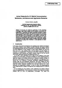
together into a small geographical area. In this section we show that network congestion due to active tracking, caused by increasing concentration of tracked users at a single cell, can happen on the order of minutes. In addition to that, we examine how to ease such situation by adopting a leaky-bucket traffic-shaping algorithm on the side of the Location Server. Let us consider a cell with 2-TRX, the SDCCH/8 configuration and 300 users, in which the number or tracked users constantly increases over time, as they arrive into the cell from the neighbor cells. Let λ denote the intensity of arrival of tracked users in the cell. Figure 14 shows, with solid lines, how GoS degrades over time when the tracked users keep concentrating in the cell. In consistence with results presented in Section 5.4.1, with λ > 16 tracked users arriving in the cell every minute, the desired SDCCH GoS can be exceeded in less than 2 minutes. Such intensity of arrivals can be observed for example before sport events, when tens of thousands of fans meet at a stadium within an hour or two. To deal with the adverse impact of active tracking on signaling capacity in the cell, we suggest to adopt a leaky-bucket traffic-shaping mechanism to limit the number of positioning requests. A leaky bucket [73] can be represented as a queue with the input flow of positioning requests. Arriving requests are enqueued, and then removed from the queue at a fixed rate r. Thus, the Location Server generates only r positioning requests per minute at a cost of lengthening the desired tracking interval δ. Figure 14 shows, with dashed lines, how traffic shaping with rate r = 6 positioning requests/min helps to keep GoS under the desired limit. However, because the arriving users bring additional signaling and traffic load, and not only the SDCCH load caused by active tracking, GoS degrades proportionally to the number of users in the cell nonetheless.
5.5. User Mobility Many applications of active tracking are particularly focused on positioning of users who reside in the same geographical area, such as employees of one company, or the ones who share similar interests, for example tourists. Mobility of such tracked users may represent a significant problem: as demonstrated in previous Section 5.4, a dense concentration of tracked users at one cell or at the same location area brings additional signaling load due to active tracking, which might render that particular network part inoperable. Even if a purely random user-pool selection is made, an occasion such as a major sports event may still bring the tracked users 17
Ericsson W810i, P900 and K750i legacy mobile phones. The phones were initially fully charged and then their battery states were read every 4 hours over the period of 100 hours. During the experiment, the tested phones were switched on in the ready state and placed at one single location at room temperature. They performed no other activity (such as calls or SMS reception) to provide stable conditions. Afterwards, the same measurement was repeated with the phones tracked at 1-minute intervals. Figure 16 shows the impact of active tracking on battery states. The tracked device consumes approximately two times more energy in the case when it is tracked with 1 minute period than without tracking (for details refer to [16]). This interval was chosen to obtain the upper bound of energy consumption — the actual interval will most likely be higher for the majority of location tracking applications [54], which would result in a proportionally lower battery drain. In 3G networks such as UMTS, the power consumption for sending a text message is slightly higher when compared to GSM [74]. On the other hand, 3G networks offer data connections with higher rates and even lower consumption in terms of energy per bit. A data-oriented approach to tracking a mobile terminal may thus represent a more energy-efficient option in such networks — for example by sending a ping message over the ICMP protocol. Figure 17 shows that with shorter tracking in-
100 32 16
Grade of Service [%]
10 2 1 0.5
TCH GoS Limit 4
SDCCH GoS Limit
λ 0.1
32 16
0.01
4 λ [users/minute]
0.001
0
TCH GoS SDCCH GoS active tracking with traffic shaping 2
4
6
8
10
12
14 16 18 time [min]
20
22
24
26
28
30
Figure 15: Impact of increasing number of tracked users on TCH GoS in a cell.
Figure 15 depicts the impact of the increasing concentration of tracked users at a cell on GoS of the traffic channels. Since active tracking brings additional load to SDCCHs only, the increase in TCH load and therefore the worse GoS is caused purely by new users in the cells. The TCHs load reaches 2% GoS when 410 users are present in the cell. The most important observation is that the expected SDCCH GoS for a particular λ hits the SDCCH GoS limit long after the TCH GoS limit is reached. As a result, active tracking with the leaky bucket traffic shaping mechanism can spare signaling capacity of the cell, but since arriving users would bring additional voice traffic load, the limiting factor become the capacity of the traffic channels anyway. 5.6. Impact on Tracked Mobile Terminal
Battery state [%]
100
The regular positioning of a tracked mobile terminal by receiving an SMS has no impact on the terminal’s memory because SMS Class 0 is not saved in the memory of the terminal [42]. Moreover, neither display back-light nor any sound alert is activated during the SMS Class 0 delivery. The only observable impact on the tracked terminal is its increased energy consumption during the SMS delivery and thus shorter battery lifetime. In this section, we discuss the impact of active tracking on mobile-terminal energy consumption, considering various network architectures. We provide an empirical measurement of battery lifetime during active tracking in controlled conditions, when the tracked phone stays untouched in the ready state. In addition to that, we show that under common usage patterns, energy consumption due to active tracking is negligible when compared to energy consumption of other mobilephone subsystems. To capture how much the energy consumption is influenced by SMS-based active tracking in a GSM network, we performed the following experiment on Sony
75 50 25 0
Without tracking Tracking (1 min)
12
24
36
48 Time [h]
60
72
84
96
72
84
96
72
84
96
(a) Sony Ericsson K750i
Battery state [%]
100 75 50 25 0
Without tracking Tracking (1 min)
12
24
36
48 Time [h]
60
(b) Sony Ericsson W810i
Battery state [%]
100 75 50 25 0
Without tracking Tracking (1 min)
12
24
36
48 Time [h]
60
(c) Sony Ericsson P900 Figure 16: Impact of tracking on GSM terminal battery state
18
6. Related Work
Battery state [%]
100 75
Various papers have already dealt with positioning of mobile entities in mobile networks. Paper [79] summarizes the main approaches to positioning, including the Cell-ID technique we use. Authors of [80] provided a short overview of network-based positioning methods. The advantages and disadvantages of using CellID positioning are discussed in [4] on the example of location-based voice applications, while we focus on the impact of active tracking on the network in general. Similarly to the SMS-based active tracking, a method related to the use of existing signaling primitives in mobile network for mobile phone positioning was proposed in [81]. However, the authors propose a modification of the signaling primitives, which is almost impossible in a live mobile network. Our work uses only those signaling primitives available even in the very first generations of GSM. Alternative positioning techniques are discussed in [82, 23, 83, 22, 84]. Systematic energy-efficient techniques of position tracking have been discussed in [85]. In recent years, Location-Based online Social Networks (LBSNs) [86], such as Google Latitude [5] or Foursquare [6], have become very popular and even giving rise to a plethora of new research work [87, 88]. Even though these applications drive the evolution of geo-location based services, they are not a direct competitor to active tracking, which addresses a different segment of requirements. LBSNs require software installation, enlisting in a particular LBSN, and they rely on mobile terminals or even on direct user activity. Localizing passive, non-communicating users is beyond the reach of LBSNs. On the other hand, LBSNs are not privacy-intrusive, since their users report their GPS coordinates or currently visible cells over the network for the purpose of positioning only when they want to. However, the granularity of user-triggered tracking with LBSNs is much more limited than with periodic active tracking. There are numerous use-cases of network-based active tracking. They span the area of tracking criminal suspects [89], mobile network optimization in terms of roaming traffic [90, 9], or prediction of future user-cell association [91]. Active tracking was tested in the investigation of the daily activity and mobility patterns of city inhabitants and commuters in Tallinn [17]. The same team used passive tracking for investigating the spatial mobility of tourists [92]. The possible use of mobile phone location data in urban analyses is shown in the example of Graz, Austria, as described in [93].
50 no tracking
25 20 s 40 s 0 0
12
24
150 s 36
48
300 s 60
72 84 Time [h]
96
108
120
132
144
Figure 17: Expected impact of tracking on a 3G-terminal battery state. Nokia 6630 phone, 900 mAh battery capacity. An interpolation from energy consumption measured in [12].
tervals the tracked device could consume approximately 2.2 to 5.5 times more energy than without tracking. The impact of active tracking on the mobile-terminal energy consumption is obvious: a shorter tracking interval leads to a higher battery drain so a user might need to recharge the mobile terminal more often. To quantify the additional energy consumption, caused by SMS-based active tracking under common usage patterns, we provide the following calculation, comparing energy consumption of the mobile-terminal LCD backlight during the day and energy consumption of the SMS delivery. An extensive empirical study [75] shows that users interact with their mobile terminals intensively, on average 1.68 hours every day. It means that the device’s LCD backlight is on for 1.68 × 3,600 = 6,048 seconds per day on average. Considering that only LCD’s backlight itself consumes in 2 seconds approximately the same amount of energy as receiving 1 SMS [76], we can calculate that tracking of the mobile terminal with a 60 s interval over one day (1,440 SMSes in total) consumes about (2×1,440/6,048) × 100 = 47.62% of the LCD’s daily energy budget. Knowing that the LCD’s share of the total device energy consumption ranges from 5 to 15% [77], depending on usage patterns, the active-tracking share of the daily energy consumption would be about 2.38% to 7.14%. Making the assumption that the battery lasts for 40 hours to 21 hours [77] under a low and high usage pattern respectively, the additional energy expense would reduce the battery lifetime approximately by 1 hour to 1.5 hours. However, it is not a concern because more than 90% of all users initiate battery charging at times when the battery level is still above 7% [78]. We conclude that SMS-based active tracking would not force the vast majority of users to change their charging habits, and thus the impact could be considered insignificant. 19
The constraints of active tracking are close to SMS attacks and flash-crowd events studied in [60, 62, 67]. However, this paper is the first to focus on periodic sending of SMS and its impact on the core network, radio access network, and the mobile terminal.
technological foundation for a broad class of applications to which its features are vital: network diagnostics, crime prevention, energy-consumption control, urban planning or sociological studies. Acknowledgements
7. Conclusion We sincerely thank our colleagues, namely Kateˇrina Dufková, Petr Vláˇcil and Martin Tomek, who significantly contributed to the SS7Tracker project. We strongly appreciate the work of the former SS7Box developers, namely Jan Mlynáˇr, Ivo Danihelka, Jiˇrí Danihelka, Ivan Gregor, Jan Kouba and Jaroslav Vrána. We thank Vodafone Czech Republic a.s. and Vodafone Foundation Czech Republic for their kind continuous support of the project. We also thank Microsoft Research for supporting this work through its PhD Scholarship Programme and Charles University for supporting this work through GAUK project No. 378111.
We presented SMS-based active tracking in the mobile network, a network-based method for obtaining positioning data of mobile users’ terminals. This method can track any user, equipped with an arbitrary mobile phone, in any type of contemporary mobile network. In comparison to other tracking methods, it represents a singular alternative to obtaining positioning data of those mobile network users who resist or are unable or uninterested to cooperate for technical, privacy, security or business reasons. SMS-based active tracking will work in any of the many legacy GSM networks all around the world, making it attractive in spite of the upcoming fourth generation of mobile networks (LTE, LTE-A). As shown, it is a conceptually scalable technology, in many aspects — one may increase the interconnection capacity between the Location Server and the network, boost Location Server’s hardware, install signaling equipment with higher throughput, or deploy multiple Location Servers to the network. However, constraints of mobilenetwork radio access technology, non-exceedable beyond a technology-specific value, constitute the principal limitation of active tracking and need to be carefully considered at deployment. We have demonstrated that a practical active network-based tracking platform can be implemented even in an academic environment, using off-the-shelf computing equipment. Furthermore, the platform can easily be deployed in a live GSM network, without being intrusive, and yields sufficient performance to continuously track tens of thousands of users with a period on the scale of minutes. Active tracking is a technology uniquely capable of delivering fine-grained human-mobility data that do not depend on user communication mode or terminal type. For example for studies of users roaming between mobile network operators, different countries or various access technologies, such a method is indispensable, which makes it highly desired by network operators. While many aspects associated with network-based active tracking remain open for research work (such as security and privacy of the tracking data), we conjecture that the cost-effectiveness of active-tracking will be the determining factor driving its future adoption as
References [1] Mobile Marketing Association, Mobile location based services marketing whitepaper, 2011. [2] W. Holden, Mobile location based services: Applications, forecasts & opportunities 2010 - 2014, 2010. [3] Nokia Corporation, Nokia maps, 2011. [4] E. Trevisani, A. Vitaletti, Cell-ID location technique, limits and benefits: an experimental tudy, in: WMCSA ’04, pp. 51–60. [5] Google Inc., Google Latitude, 2010. [6] Foursquare Labs, Inc., Foursquare, 2012. [7] P. Schmitz, A. Cooper, Using mobile phone data records to determine criminal activity space, in: IQPC ’07, pp. 1–29. [8] K. Dufková, M. Ficek, L. Kencl, J. Novak, J. Kouba, I. Gregor, J. Danihelka, Active GSM cell-ID tracking: "where did you disappear?", in: ACM MELT ’08, pp. 7–12. [9] M. Ficek, L. Kencl, Improving roamer retention by exposing weak locations in GSM networks, in: Co-Next Student Workshop ’09, pp. 17–18. [10] A. Küpper, Location-Based Services: Fundamentals and Operation, Wiley, 2005. [11] B. Richton, G. Vannucci, S. Wilkus, Assisted GPS for wireless phone location – technology and standards, 2002. [12] H. Haverinen, J. Siren, P. Eronen, Energy consumption of always-on applications in WCDMA networks, in: VTC Spring, IEEE, 2007, pp. 964–968. [13] Ericsson, Positioning with LTE – maximizing performance through integrated solutions, 2011. [14] 3GPP, TS 45.811: Feasibility study on Uplink TDOA in GSM and GPRS, 2002. [15] M. Ficek, L. Kencl, Inter-Call mobility model: A spatiotemporal refinement of call data records using a gaussian mixture model, in: INFOCOM ’2012, pp. 469–477. [16] M. Ficek, T. Pop, P. Vláˇcil, K. Dufková, L. Kencl, M. Tomek, Performance study of active tracking in a cellular network using a modular signaling platform, in: MobiSys ’10, pp. 239–254. [17] R. Ahas, A. Aasa, S. Silm, R. Aunap, H. Kalle, Ü. Mark, Mobile positioning in space-time behaviour studies: Social positioning method experiments in estonia, CaGIS 34 (2007) 259–273.
20
[18] M. Ficek, L. Kencl, Spatial extension of the Reality Mining Dataset, in: IEEE MASS ’2010, pp. 666–673. [19] R. Singel, Cell-Phone Tracking: Laws Needed, 2006. [20] C. Kang, China plans to track cellphone users, sparking human rights concerns, 2011. [21] H. Zang, J. Bolot, Anonymization of location data does not work: a large-scale measurement study, in: MobiCom ’11, pp. 145–156. [22] A. Varshavsky, M. Y. Chen, E. de Lara, J. Froehlich, D. Haehnel, J. Hightower, A. LaMarca, F. Potter, T. Sohn, K. Tang, I. Smith, Are GSM phones THE solution for localization?, in: WMCSA ’06, pp. 20–28. [23] I. Smith, J. Tabert, T. Wild, A. Lamarca, A. Lamarca, Y. Chawathe, Y. Chawathe, S. Consolvo, S. Consolvo, J. Hightower, J. Hightower, J. Scott, J. Scott, T. Sohn, T. Sohn, J. Howard, J. Howard, J. Hughes, J. Hughes, F. Potter, F. Potter, P. Powledge, P. Powledge, G. Borriello, G. Borriello, B. Schilit, B. Schilit, Place Lab: Device Positioning Using Radio Beacons in the Wild, in: Pervasive ’05, pp. 116–133. [24] M. Vakulenko, S. Schuermans, A. C. andMatos Kapetanakis, Mobile platforms: The clash of ecosystems, 2011. [25] F. Aurenhammer, Voronoi diagrams - a survey of a fundamental geometric data structure, ACM Comput. Surv. 23 (1991) 345– 405. [26] 3GPP, TS 44.035: Broadcast network assistance for enhanced observed time difference (E-OTD) and global positioning system (GPS) positioning methods, 2009. [27] 3GPP, TS 36.355 : LTE; Evolved universal terrestrial radio access (E-UTRA); LTE positioning protocol (LPP), 2011. [28] 3GPP, TS 03.71: Location services (LCS); Functional description; Stage 2., 2004. [29] QUALCOMM Company, Location technologies for GSM, GPRS and UMTS networks, 2003. [30] 3GPP, TS 43.059: Functional stage 2 description of location services (LCS) in GERAN, 2007. [31] 3GPP, TS 05.10: Radio subsystem synchronization, 1999. [32] 3GPP, TS 45.010: Radio access network; Radio subsystem synchronization, 2011. V9.0.0. [33] J. Borkowski, J. Niemela, J. Lempiainen, Performance of cell ID+RTT hybrid positioning method for UMTS radio networks, in: EW ’04, pp. 24–27. [34] 3GPP, TS 49.031: Location services (LCS); BSSAP-LE, 2011. V10.0.0. [35] T. Wigren, Adaptive enhanced cell-ID fingerprinting localization by clustering of precise position measurements, IEEE Trans. Veh. Technol. 56 (2007) 3199–3209. [36] L. Shi, T. Wigren, AECID fingerprinting positioning performance, in: IEEE GLOBECOM ’2009, pp. 1–6. [37] Y. J. Guo, Advances in Mobile Radio Access Networks, Artech House, Inc., 2004. [38] M. Pettersen, R. Eckhoff, P. Lehne, T. Worren, E. Melby, An experimental evaluation of network-based methods for mobile station positioning, in: PIMRC ’02, pp. 2287–2291. [39] TruePosition, Inc., U-TDOA: Enabling new location-based safety and security solutions, 2008. [40] 3GPP, TS 29.002: Mobile application part (MAP) specification, 2002. V3.13.0. [41] 3GPP, TS 36.304: Evolved universal terrestrial radio access (EUTRA); user equipment (UE) procedures in idle mode, 2011. V10.3.0. [42] 3GPP, TS 23.038: Alphabets and language-specific information, 2008. V7.0.0. [43] ETSI, European digital cellular telecommunications system (phase 2); Point-to-point (PP) short message service (sms), 1995.
[44] C. Gessner, O. Gerlach, Voice and SMS in LTE, 2011. [45] 3GPP, TS 30.90: Unstructured Supplementary Service Data (USSD) - Stage 2, 1999. V7.0.0. [46] A. Berg, Method for providing location information, United States Patent No. 20020160789, 2002. [47] 3GPP, TS 09.78: Customised applications for mobile network enhanced logic (CAMEL); CAMEL application part (CAP) specification, 2000. V.7.1.0. [48] R. Noldus, CAMEL: Intelligent Networks for the GSM, GPRS and UMTS Network, John Wiley & Sons, 2006. [49] G. Heine, M. Horrer, GSM Networks: Protocols, Terminology, and Implementation, Artech House, 1999. [50] S. Keshav, An Engineering Approach to Computer Networking: ATM Networks, the Internet, and the Telephone Network, Addison-Wesley, 1997. [51] ITU-T, Introduction to CCITT Signalling System No.7, 1993. [52] Dialogic, SPCI4 user manual, 2007. [53] ITU-T, Methods for dimensioning resources in Signalling System No.7 networks, ITU-T Recommendation E.733, 1998. [54] 3GPP, TS 22.071:Location services (LCS); Service description; Stage 1., 2011. V10.0.0. [55] Dialogic, Dialogic DSI SS7 protocol stack MAP programmer’s manual, 2009. [56] Dialogic, Dialogic DSI signaling interface unit based on dialogic DSI SS7G3x signaling servers, 2009. [57] A. Chukarin, N. Pershakov, K. Samouylov, Performance of Sigtran-based signaling links deployed in mobile networks, in: ConTel ’07, pp. 163–166. [58] Intersec, Multi channel gateway - next generation SMS-C, 2012. [59] 3GPP, TS 24.011: Point-to-point (PP) short message service (SMS) support on mobile radio interface, 2011. [60] P. Traynor, W. Enck, P. McDaniel, T. La Porta, Mitigating attacks on open functionality in SMS-capable cellular networks, IEEE/ACM Trans. Netw. 17 (2009). [61] Ericsson, Location area dimensioning guideline, 2002. 19/10056-HSC 103 12/4 Rev C 2005-06-09. [62] W. Enck, P. Traynor, P. McDaniel, T. La Porta, Exploiting open functionality in SMS-capable cellular networks, in: ACM CCS ’05, pp. 393–404. [63] National Communications System, SMS over SS7, 2003. [64] Y. Qian, D. Tipper, S. Sasanus, Impact of signaling load on the UMTS call blocking/dropping, in: IEEE VTC ’08, pp. 2507– 2511. [65] G. Camarillo, M.-A. Garcia-Martin, The 3G IP Multimedia Subsystem (IMS): Merging the Internet and the Cellular Worlds, Second Edition, John Wiley & Sons, 2006. [66] 3GPP, TS 23.272: Circuit switched fallback in evolved packet system, 2008. V8.0.0. [67] X. Meng, P. Zerfos, V. Samanta, S. Wong, S. Lu, Analysis of the reliability of a nationwide short message service, in: IEEE INFOCOM ’07, pp. 1811–1819. [68] M. Stasiak, M. Glaabowski, A. Wisniewski, P. Zwierzykowski, Modeling and Dimensioning of Mobile Networks: From GSM to LTE, John Wiley & Sons, Ltd, 2010. [69] Ericsson, SDCCH dimensioning guideline the Ericsson GSM system, 2005. 14/100 56-HSC 103 12/4 Uen B2 2005-08-23. [70] C. Palm, Table of the Erlang Loss Formula, C.E. Fritzes Hovbokhandel, 1947. [71] M. Schwartz, Mobile Wireless Communications, Cambridge University Press, 2004. [72] Ericsson, Adaptive configuration of logical channels, 2005. 82/1553-HSC 103 12/4 Uen A1 2005-06-03. [73] A. S. Tanenbaum, Computer Networks (4th Edition), Prentice Hall PTR, 2002. [74] G. Perrucci, F. Fitzek, G. Sasso, W. Kellerer, J. Widmer, On the
21
[75] [76]
[77] [78] [79] [80]
[81] [82]
[83]
[84]
impact of 2G and 3G network usage for mobile phones’ battery life, in: EW ’09, pp. 255–259. E. Oliver, The challenges in large-scale smartphone user studies, in: HotPlanet ’10, pp. 1–4. T. Armstrong, Efficient and Transparent Dynamic Content Updates for Mobile Clients, Master’s thesis, University of Toronto, 2006. A. Carroll, G. Heiser, An analysis of power consumption in a smartphone, in: USENIX ’10, pp. 21–21. E. Oliver, Diversity in smartphone energy consumption, in: ACM S3 ’10, pp. 25–28. K. Raja, W. Buchanan, J. Munoz, We know where you are [location tracking], Communications Engineer 2 (2004) 34–39. S. Weixiong, Z. Yanfeng, Z. Jin, Y. Chun, Collecting and analyzing mobility data from mobile network, in: IEEE ICBNMT ’09., pp. 810–815. N. Deligiannis, S. Louvros, S. Kotsopoulos, Mobile positioning based on existing signalling messages in GSM networks, 2007. A. Quigley, B. Ward, C. Ottrey, D. Cutting, R. Kummerfeld, BlueStar, a Privacy Centric Location Aware System, in: IEEE PLANS ’04, pp. 684–689. C. M. Takenga, K. Kyamakya, Robust Positioning System Based on Fingerprint Approach, in: ACM MobiWac ’07, pp. 1–8. M. Youssef, A. Youssef, C. Rieger, U. Shankar, A. Agrawala, PinPoint: An Asynchronous Time-Based Location Determina-
tion System, in: ACM MobiSys ’06, pp. 165–176. [85] M. B. Kjaergaard, J. Langdal, T. Godsk, T. Toftkjaer, EnTracked: Energy-Efficient Robust Position Tracking for Mobile Devices, in: ACM MobiSys ’09, pp. 221–234. [86] Y. Zheng, Tutorial on location-based social networks, in: WWW ’12, pp. 1–4. [87] M. Allamanis, S. Scellato, C. Mascolo, Evolution of a locationbased online social network: Analysis and models, in: IMC ’12, pp. 145–158. [88] Z. Wang, D. Zhang, D. Yang, Z. Yu, X. Zhou, Detecting overlapping communities in location-based social networks, in: SocInfo ’12, pp. 110–123. [89] S. Krygsman, P. Schmitz, The use of cell phone technology in activity and travel data collection, in: SATC ’05, pp. 1–2. [90] K. Dufková, J. Danihelka, M. Ficek, I. Gregor, J. Kouba, Can active tracking of inroamer location optimise a live GSM network?, in: ACM CoNEXT ’07 Student Workshop, pp. 1–2. [91] K. Dufkova, J.-Y. L. Boudec, L. Kencl, M. Bjelica, Predicting user-cell association in cellular networks from tracked data, in: MELT ’09, pp. 19–33. [92] R. Ahas, A. Aasa, A. Roose, C. Mark, S. Silm, Evaluating passive mobile positioning data for tourism surveys: An Estonian case study, Tourism Management 29 (2008) 469–486. [93] C. Ratti, A. Sevtsuk, S. Huang, R. Pailer, Mobile landscapes: Graz in real time., 2007.
22