Jul 7, 2002 - LORD Corporation's Active Vibration Control Systems (AVCS) using Circular Force Generators (CFG) can provide significant improvements in ...
ACTIVE VIBRATION CONTROL USING CIRCULAR FORCE GENERATORS Douglas Swanson, Paul Black, Victor Girondin, Paul Bachmeyer, Mark Jolly LORD Corporation, 110 Lord Drive, Cary NC 27511, USA Abstract LORD Corporation’s Active Vibration Control Systems (AVCS) using Circular Force Generators (CFG) can provide significant improvements in vibration reduction, weight, power, and modularity over existing helicopter vibration control systems. The AVCS allows for a modular design approach both in hardware where a mixture of accelerometer types and CFG design variants can be used, as well as, in software where tuning of the system is done through the use of Parameter Data Item Files. CFGs allow for the production of diverse force shapes at a significantly lower weight than traditional linear force generators. The CFGs also require low power with significant reduction in power over a broad frequency range with good applicability for variable rotor speed helicopters. Laboratory based experiments show that AVC with circular force inputs can produce similar or improved vibratory reduction both in steady state and transient conditions. 1. INTRODUCTION Rotor Speed/ Position Sensor
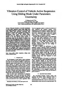
Helicopter vibration directly affects pilot, crew, and passenger comfort, as well as, fatigue life of the structural, mechanical, and electrical components on the helicopter. Traditionally passive vibration reduction devices have been used to reduce vibration. In more recent years, active vibration control (AVC) solutions have emerged in industry and are now being designed into many existing and new helicopter platforms. The objective of an Active Vibration Control System (AVCS) is to actively reduce the harmonics coming from the main rotor (particularly at the blade pass or N/rev frequency) through the use of vibration sensors and force generators. LORD Corporation has been at the forefront of this activity offering a variety of solutions to meet industries’ ever-increasing demand for lower vibrations. This paper focuses on LORD Corporation’s Circular Force Generator (CFG) AVC solution with some comparisons made to the more traditional Linear Force Generator AVC. Although the AVCS can be equipped with a variety of digital interfaces, switches, and relays, the most basic AVCS consists of force generators, vibration sensors, main rotor speed sensor, and a controller as depicted in Figure 1.
Vibration Sensor Controller Amplifier
Force
Figure 1: Active vibration control system for helicopters
2. AVCS ARCHITECTURE FORCE GENERATORS
WITH
CIRCULAR
The system architecture for the AVCS with CFGs is shown in Figure 2. The Central Controller receives inputs from accelerometers and tachometer(s) (rotor speed sensors) and sends output command forces digitally to the CFGs. The AVCS is designed to be flexible and modular in terms of the number of accelerometers (up to 14) and Circular Force Generators (up to 12). Because the communication with the CFG is digital, the system is very flexible and the number of CFGs can be easily changed through a software configuration Parameter Data Item File (PDIF).
Figure 2: Active vibration control architecture with CFGs The Central Controller (CC) as shown in Figure 3 is responsible for handling all I/O for the AVCS. The proprietary LORD AVC algorithm is embedded into the electronics which in addition to performing the AVC function, is capable of communicating with a user interface, transmitting and receiving ARINC-429 and RS-422 data, processing discrete inputs, providing relay outputs, and storing in-flight data. Additionally, the CC tracks system performance and flags any fault to a log. Both sets of data can be downloaded by the operator for analysis as needed.
Figure 4: Circular Force Generators In addition to the mechanical and electrical flexibility, the AVCS provides flexibility in terms of the software. Parameter Data Item Files are used to allow for tuning of the AVCS to meet the requirements of the target application. Parameters such as the number of CFGs, the number of accelerometers, accelerometer weighting, CFG spin direction, etc. are adjustable as required. The AVCS also provides specialized protection for failure modes such as incorrect force at high safety criticality. 3. CIRCULAR FORCE GENERATOR
Figure 3: Central Controller The CFG is designed with an integration of several systems into one package. It contains the mechanical components associated with the circular force output, as well as, the integrated electronics responsible for power input handling, motor control, digital communication with the CC, and internal monitoring of functional performance and health assessment. The CFG is currently designed with several variants that provide size and force flexibility based on application needs. The CFG variants make use of common mechanical and electronic components to maximize system commonality and allow for assembly modifications to accommodate installation requirements. Figure 4 shows the 154mm size CFG with the same electronics packaging mounted in different orientations. The system architecture can be comprised of a single design type or a mixture of all CFG design variants.
The CFGs generate circular forces by controlling two independent imbalance masses that spin at the N/rev blade pass frequency. Both rotating imbalance masses spin in the same direction (co-rotating). Each rotor creates a rotating force vector equal to the product of the imbalance authority (mr) and the angular frequency squared ( 2 ). We can define the CFGs circular force in terms of two independent rotating imbalance mass phasors (A and B).
(1)
2 j A 2 j B Fc m A rA e mB rBB e ,
where mA and mB are the imbalance masses, rA and rB are the radiuses from the rotational axis to the center of each mass, and and are the angular positions of each mass. The circular force can also be projected to rectilinear coordinates by taking the real part of equation 1 as the x-axis force and the imaginary part as the y-axis force. Additionally, if we assume that the imbalance authority (mr) between mass A and B are equal, and both masses are spinning at the same nominal frequency, then equation 1 can be written in simplified complex notation with in-phase (cosine) and quadrature (sine) components,
cos A cos B Fc mr 2 , j sin A j sin B
(2)
where and are the phase angles of each imbalance mass relative to a common reference signal provided by the helicopter main rotor tachometer. When the two imbalance masses are phased opposite each other, the net force created by the CFG is zero. When the two imbalance masses are phased together, the force generated by the CFG is maximized (see Figure 5). By continuously adjusting the relative phase between the imbalance masses, the magnitude and phase of the applied circular force can be used to cancel out the forces created by the main rotor. Rotating force of constant magnitude
Single imbalance rotors
Fc
Two co-rotating imbalance rotors mB mA
y x
Controllable circular force (θA-θB)=π/2
Zx
Fy Fx , Zy , x y
where Fx and Fy are the equivalent external loads that create the disturbance vibration which the CFG is trying to control. We can generally approximate the structural impedance using a simple parallel mass-spring-damper arrangement in both the x and y directions. The values for the mass, stiffness, and damping can be estimated through experimental data or dynamic models of the airframe.
(4)
(θA-θB)=0
(θA-θB)=3π/4
(3)
For example, if the complex structural inertance is known at the AVC control frequency ( ), this can be used to solve for the parameters of a 1st order impedance model (m, k, b),
m r
This model requires knowledge regarding the structural impedance at a given aircraft installation location,
(θA-θB)=7π/8
x j 2 x j j x j . Fx j k x mx 2 jbx
Note that if a single degree of freedom model does not accurately capture the structural impedance, a higher order model should be used.
Figure 5: Circular force generation depiction 4.1. 4. CFG DYNAMIC MODEL The CFG can be modelled as two independent imbalance masses rotating in a circular motion with fixed radius r as indicated in Figure 6. The imbalance masses are controlled to move by applying torques TA and TB, which are generated through independent motors. It is also assumed that the gravitational body force (g) is acting in the x direction.
State Equations
The translational and rotational dynamics for the CFG are extracted below in the following state equations. State equation for momentum in the x-direction, M mA mB x Z x x Fx mA g A2r cos A (5) mB g B 2r cos B mAAr sin mBB r sin B
.
State equation for momentum in the y-direction, M mA mB y Z y y Fy mA A2r sin A (6) . mB B 2r sin B m AAr cos mBB r cos B
State equation for angular momentum of mass A,
(7) J AA A T A m A rsin A x g cos A y .
State equation for angular momentum of mass B,
(8) J BB BB TB mB rsin B x g cos B y . 4.2.
Mechanical Torque and Power
The state equations for angular momentum can be rearranged to describe the required motor torque per motor, Figure 6: Circular force generator schematic
(9) T A J AA A m A rg sin A m A ry cos A x sin A , (10) T J m rg sin m ry cos x sin , B
B B
B B
B
B
B
B
B
For the linear force generators, the x- and y-axis forces are expressed as,
Fx F L1 , Fy F L2
(13)
where J is the polar moment of inertia about the rotational axis, β is the rotational damping constant. To provide better physical meaning, the terms in Equation 9 and 10 can be grouped into the following components,
(11) Tmotor Tinertial T friction Tgravity Tbase motion . The required mechanical power for the CFG to operate properly is equal to the product of the motor toque and angular frequency of each imbalance rotor, (12)
PCFG TA A TBB .
where FL1 and FL2 represent the complex linear force commands relative to the main rotor tachometer reference. For the CFGs, the x- and y-axis forces are expressed as,
(14)
Fx Fc1 Fc 2 , F y jFc1 jFc 2
where Fc1 and Fc2 represent the complex circular force commands to CFG 1 and CFG 2 respectively. The j operator represents a +90o rotation of the force vector and –j represents a -90o rotation.
5. LINEAR AND BI-DIRECTIONAL FORCE GENERATION
The specific force mapping expressions change based on the desired force profile and the aircraft installation, and can be configured as part of a PDIF.
When two CFGs are mounted close together, and spun in opposing directions, the resultant force created by the pair becomes bi-directional in a plane. In order to better understand this concept, the bi-directional force of two traditional linear force generators is compared to two CFGs.
Table 1 shows the complex force commands that are required to produce each of the bi-direction force profiles shown in Figure 8. In the table, the commanded force is normalized to a maximum value of one.
To create a bi-directional force with two linear force generators, it requires that two linear force generators are mounted so that the force directions are orthogonal. For CFGs to create bi-directional force, two CFGs must be spinning in opposite directions and have parallel force planes (example: side by side or back to back). It should also be noted that separation of the circular force axes or planes can result in an additional applied moment.
Table 1: Bi-directional forces with linear force generators and CFGs Pair of linear force Case generators Pair of CFGs 1. Linear force (x) 2. Linear force (y) 3. Circular force
FL2
4. Elliptical (x)
FL1
5. Elliptical (y)
y
Fc1
Fc2
x
Figure 7: Bi-directional force setup for (Top) two orthogonal linear force generators, (Bottom) two counter-rotating CFGs
FL1 1 FL 2 0
Fc1 0.5 Fc 2 0.5
FL1 0 FL 2 1
Fc1 0.5 j Fc 2 0.5 j
FL1 1 FL 2 j
Fc1 1 Fc 2 0
FL1 1 FL2 0.25 j
Fc1 0.63 Fc 2 0.38
FL1 0.25 j
F 0.38 j c1
FL 2 1
Fc 2 0.63 j
6. Linear (x-y)
FL1 0.7 0.7 j FL2 0.7 0.7 j
Fc1 0.7 Fc 2 0.7 j
7. Elliptical (x-y)
FL1 0.7 0.7 j FL 2 1
Fc1 0.35 0.15 j Fc 2 0.35 0.85 j
Figure 8: Bi-directional force profiles discussed in Table 1 From Table 1, we can observe that a pair of CFGs are able to achieve 40 - 100% larger linear force profiles depending on the phasing between the x and y direction forces. The maximum linear force produced by a pair of CFGs vs. a pair of linear force generators is compared in Figure 9. The pair of linear force generators is limited to the red square boundary. In contrast, the maximum output force of a pair of CFGs is bounded by the blue circle.
Figure 10: Examples of different possible bidirectional force profiles that can be generated by a CFG pair
6. CONTROL FORCE MAPPING When force generators are placed close to one another, there can be some benefits from mapping forces together. This can help prevent control forces from fighting against each other, as well as, preventing forces in directions in which the structure cannot tolerate loading. Mapping is implemented with a mapping matrix (Γ) between control forces and actual forces. The block diagram in Figure 11 depicts how this mapping matrix is applied. Disturbance (d) + Force Update
Fmap
Γ
Fc
AVC Controller
Secondary Path (C)
+
Σ
e
Physical System
Figure 11: Block diagram of AVC controller with force mapping Figure 9: Maximum force output for two linear force generator pair (red line) and CFG pair (blue line). When the commanded bi-directional force profile of a CFG pair is elliptical, the maximum possible force becomes smaller as the minor axis of the desired elliptical force becomes larger. This is illustrated in Figure 10.
As an example, a linear to circular mapping matrix is found by taking the inverse of equation (14) shown previously,
(15)
Fc1 0.5 0.5 j Fx F . c 2 0.5 0.5 j Fy
CFGs can also be mapped together to create a larger circular force. A two CFG example is shown in equation (16), but this can be expanded to combine as many CFGs as desired,
(16)
Fc1 0.5 0 Fc _ map F . c 2 0.5 0 0
weight on the y axis. The plot demonstrates that the weight efficiency of a single CFG is the best, followed by a pair of CFGs, and then the traditional linear force generator. In addition, one can observe that the weight savings is most significant as higher force authorities are needed - which is typically the case for medium to large helicopters (H/C). 1
An example of a combined mapping matrix is given in the following equation, 0 0 0 0 0 0 0 1 0 0 0 1 0 0 0 0 0 0
Fc_map 0 0 0 0 0 Fc3 , 0 0 Fc4 0.5 0.5 j Fx 0.5 0.5 j Fy 0
0
Normalized Weight
(17)
Fc1 0.5 F c2 0.5 Fc3 0 Fc4 0 Fc5 0 Fc6 0
0.9
where Fc1 and Fc2 are mapped to a combined circular force, channels Fc3 and Fc4 are unmapped circular forces, and channels Fc5 and Fc6 are bi-linearly mapped. With this type of control structure, it is easy to turn off or limit mapped forces by disabling or setting a saturation limit on the mapped control forces in software.
In the following subsections, a comparison is made for weight and power between 3 different force generation options. 1. Single CFG 2. Single traditional linear force generator (see ref. 3-7) 3. Pair of CFGs, capable of bi-directional force generation For the comparisons below, the maximum force output of each is the same. Consequently, for the pair of CFGs (3), each CFG has half of the output force compared to the individual CFG (1) and linear force generator (2). 7.1.
Linear Force Generator CFG Pair (Bi-directional Force)
0.7 0.6 0.5 0.4 0.3 0.2
Light H/C
Medium H/C
Figure 12: Force generator weight vs. normalized force authority 7.2.
7. PERFORMANCE COMPARISON
0.8
CFG
Power Draw Comparison
Figure 13 shows a comparison of the normalized power versus normalized frequency for the three types of force generation described at the beginning of Section 7. For this comparison, the required power is indicative of each actuator outputting maximum force while mounted to a rigid structure. As can be seen, the power for the single CFG and pair of CFGs increases slightly relative to the frequency, but these changes in power are small when compared to those of the linear force generator across the frequency band. For variable speed helicopters, the CFG offers a significant power advantage for handling a wide frequency range.
Weight Efficiency Comparison
Weight advantages can be realized with CFGs relative to traditional linear force generators when considering force output and required total mass. This can be visualized by comparing the force authority of each type of force generator. For a linear force generator, this is the moving mass multiplied by the maximum displacement (usually stroke and fatigue life limited). For a CFG, this is the imbalance mass multiplied by the radial distance to the center of mass of the imbalance rotors. Figure 12 shows a comparison of normalized weight for a single CFG, linear force generator, and a bidirectional pair of CFGs. This is shown for several different force authorities on the x-axis and normalized
Figure 13: Power draw comparison between a single CFG, linear force generator, and pair of CFGs
8. LABORATORY TESTING OF VIBRATION CONTROL 8.1.
Vibration Control Overview
As previously discussed, the CFGs may be mounted in pairs to produce linear or bi-directional force profiles. The CFGs may also be mounted individually throughout the aircraft structure.
A simulated tachometer reference signal was also provided to the system from a function generator and the system was powered from a 28 Vdc, 40 amp bench power supply. The number, locations, and directions of accelerometers are the same for all tests. The setup can be visualized in the diagram and photographs shown in Figure 14 through Figure 17.
The optimal force profile at any given location will depend on the helicopter’s N/rev baseline vibration (d) and the dynamic response (C) of each control sensor to each control force,
(18)
e CFc d ,
where e is the error measured at each accelerometer and Fc is the control forces. The AVC control algorithm adapts the control forces to minimize e in least mean squares sense. It has been observed through laboratory and flight testing that when CFGs are mounted below the floor, typically the structure is significantly more responsive in the vertical direction as compared to the fore-aft and lateral directions. As a consequence, the CFG control performance is generally similar to controlling vibration using vertical forces. However, when using circular or bi-directional linear forces, vibration in the fore-aft and lateral directions can also be controlled. That said, it typically will take significantly higher force levels to affect vibration in these directions. 8.2.
Test Objective
The basic objective of the laboratory testing was to compare AVC performance of the three types of force profiles on a laboratory grade helicopter fuselage structure: 1. Bi-direction Force (paired CFGs) 2. Vertical Linear Force (paired CFGs and constraining force to only the vertical direction) 3. Circular Force (independently controlled CFGs) Figure 14: CFG and accelerometer test layout 8.3.
AVCS Test Setup
The test setup consisted of an S76 fuselage in LORD Corporation’s laboratory which was structurally modified to install eight CFGs under the cabin floor. In order to do this, metal brackets were added to the two main longitudinal keel beams of the fuselage. Modified floor plates were also designed to provide easier access to sensors and actuators. CFG provisions were also added in the sidewalls and nose of the fuselage, however, the test results of these locations are not included in this article.
8.4.
Simulated Disturbance
The N/rev vibration disturbance was simulated by placing two CFGs near where the rotor hub would be positioned (see Figure 18). Several different vibration profiles were examined during this study by varying the magnitude and phase of the disturbance CFGs. To compare the results below, a single disturbance profile was selected which produced 2.5 kN of dynamic in-plane loads (fore-aft and lateral) and a combined 5 kN of dynamic vertical load.
Figure 15: platform
Laboratory vibration control test
Figure 18: Disturbance CFGs installed at pylon location of the fuselage 8.5.
Figure 16: CFG installations (below floor and on sidewalls)
Steady State Performance Comparison
The best CFG configurations were found through simulation by minimizing the overall vibration level in equation 18. This optimization was performed with different numbers of control forces to investigate the effect on performance. The steady-state vibration performance and force profiles are shown for each control force case. 8.5.1.
Bi-directional Force Control
The following CFG pairs were found to be the best for bi-direction control. Table 2: Bi-directional force control test cases Number Back Back Front Front bi-dir left right right left forces CFGs CFGs CFGs CFGs 4 0, 1 2, 3 6, 7 8, 9 3 2, 3 6, 7 8, 9 2 2, 3 8, 9 Figure 17: Example of CFG and accelerometer installation below the floor
Figure 19 shows the vibration performance with the different numbers of bi-directional pairs. As expected, with more pairs, the vibration performance is improved. However, it can be seen that the vibration reduction is quite small between three pairs and four pairs. Therefore, the three pairs configuration may be a good candidate for bi-directional force control.
Since the AVCS off vibration is primarily vertical, similar to the bi-directional case, Figure 21 shows that the three and four vertical forces perform well.
Figure 19: Vibration performance comparison with different numbers of bi-directional forces The force profiles for the different bi-directional control cases are shown in Figure 20. This and other force profile plots are shown as parametric forces in the y (vertical direction) and x (fore-aft direction).
Figure 20: AVCS bi-directional force profiles created with paired CFGs 8.5.2.
Vertical Linear Force Control
Vertical control forces were created by constraining pairs of CFGs. The following CFG pairs were found to be the best for vertical force control. Table 3: Vertical force control test cases Number Back Back Front Front vertical left right right left forces CFGs CFGs CFGs CFGs 4 0, 1 2, 3 6, 7 8, 9 3 2, 3 6, 7 8, 9 2 2, 3 8, 9
Figure 21: Vibration performance comparison with different number of vertical forces
Figure 22: AVCS vertical force profiles created with paired CFGs 8.5.3.
Circular Force Control
The following CFGs were selected as the best for circular force control. Table 4: Circular force control test cases Back Back Front Front Number left right right left of CFGs CFGs CFGs CFGs CFGs 8 0, 1 2, 3 6, 7 8, 9 6 1 2, 3 6, 7 8 4 1 2 6 8
Controlling with independent circular forces allows the CFGs to be better spatially distributed. Consequently, even the four CFG test case exhibits good vibration reduction.
Four & six CFGs with circular force control
In this comparison, all 4 control sets perform well. Although the 4 CFG condition does have slightly higher vibration at a few sensors, the benefit of this configuration is that only half of the CFGs are needed (resulting in cost, power, and weight savings). Alternatively, if higher performance is desired, the 6 CFG configuration could be a good solution.
Figure 23: Vibration performance comparison with different numbers of CFGs (circular force control) The force profiles displayed in Figure 24 are calculated using equation 14. Therefore, configurations that have two CFGs at a single location show a bi-directional force profile instead of a purely circular force.
Figure 25: Vibration performance comparison with paired and unpaired CFGs (bi-directional, linear, and circular)
Figure 24: AVCS force profiles with CFGs (circular force control) 8.5.4.
Force Profile Comparison
Figure 25 shows a comparison of: AVCS off baseline vibration Four pairs for CFGs with bi-linear control forces Four pairs for CFGs with vertically constrained control forces
Figure 26: AVCS force profiles with paired and unpaired CFGs (bi-directional, linear, and circular)
8.6.
Transient Response
An evaluation of the AVCS transient performance is
shown in Figure 27. This figure shows:
Transient vibration with AVCS off Four pairs of CFGs doing bi-directional control Four pairs of CFGs doing vertical control Four & six CFGs doing circular control
The disturbance profile is intended to represent a significant transient vibration condition such as a flare. The disturbance profile shown consists of three successive parts:
0.7 kN in-plane & 1.4 kN vertical load from zero to five seconds 2 kN in-plane & 4 kN vertical load from five to ten seconds 0.5 kN in-plane & 1 KN vertical load from ten to fifteen seconds
The vibration performance is similar between the three cases. However, there is some small performance improvement with the circular and bi-directional control in terms of the fore-aft vibration.
generators. They also provide equivalent or better vibration performance in both steady and transient conditions. 11. REFERENCES [1] Mahmood, Raheel, Heverly, David, “In-Fight Demonstration of Active Vibration Control Technologies on the Bell 429 Helicopter,” AHS Forum 68, Fort Worth, Texas, May 1-3, 2012. [2] Konstanzer, Peter, Enenkl, Bernhard, Aubourg, Pierre-Antoine, Cranga, Paul, “Recent Advances in Eurocopter’s Passive and Active Vibration Control,” AHS Forum 64, Montreal, Canada, April 29-May 1, 2008. [3] Vignal, Berengere, Kryzinski, Tomasz, “Development and Qualification of Active Vibration Control System for the EC225/EC725”, AHS Forum 61, Grapevine, Texas, June 1-3, 2005. [4] Heilmann, John, Swanson, Doug, Badre-Alam, Askari, Rao, K.S. Narayana, “Vibration Attenuation Through the Use of Active Frahms,” AHS Forum 59, Phoenix, Arizona, May 6-8, 2003. [5] Hoffmann, Falk, Konstanzer, Peter, Priems, Martijn, Chemin, Jerome, “Active Cabin Vibration Reduction for Jet-Smooth Helicopter Ride,” 35th European Rotorcraft Forum 2009, Hamburg, Germany, September 22-25, 2009. [6] Priems, Martijn, Dreher, Stefan, Konstanzer, Peter, Hoffmann, Falk, Kerdreux, Benjamin, Jouve, Jeremy, “Active Vibration Control for Light Single and Twin Engine Helicopters”, AHS Forum 68, Fort Worth, Texas, May 1-3, 2012.
Figure 27: comparison
AVCS
transient
performance
9. CERTIFICATION The AVCS with Circular Force Generators is EASA certified and has been successfully flight tested on more than 5 different helicopter models.
10. CONCLUSION This article introduced LORD CFG active vibration control technology. As discussed, CFGs provide significant improvement in modularity, weight, and power when compared to traditional AVC linear force
[7] Priems, Martijn, Kerdreux, Benjamin, Dreher, Stefan, Jouve, Jeremy, Marrot, Franck, Reymond, Mael, “Vibration Comfort Improvement through Active Vibration Control and its Certification on EC130T2”, 38th European Rotorcraft Forum, September 2012. [8] Welsh, W., Fredrickson, C., Rauch, C., Lyndon, I., “Flight Test of an Active Vibration Control System on the UH-60 Black Hawk Helicopter,” AHS Forum 51, Fort Worth, Texas, May 9-11, 1995. [9] Millott, Thomas, Goodman, Robert, Wong, Jonathan, Welsh, William, Correia, James, Cassil, Charles, “Risk Reduction Flight Test of a Pre-Production Active Vibration Control System for the UH-60M,” AHS Forum 59, Phoenix, Arizona, May 6-8, 2003.