ActiveX based Device Driver Rahul S.Pol1, S. P. Mahajan2, M.Murugan3 1, 3
Department of Electronics & Telecommunication Engineering, Vishwakarma Institute of Information Technology, Pune-48, Maharashtra, India. 2 . Department of Electronics & Telecommunication Engineering, College of Engineering, Pune-5. Maharashtra, India. e-mail:
[email protected],
[email protected],
[email protected] Abstract This paper initially gives a brief idea of creating user defined device driver with a greater simplicity. ActiveX based Device Driver Model (ADDM) provides benefits of component object method (COM) and object oriented technology to device support. The ActiveX based Device Driver Model represents an innovative advance in Input/0utput (I/O) software technology. Combining the power of component objects method with the flexibility of frameworks, the ADDM gives us the benefits of rapid I/0 software developments, broadbased compatibility and portability, plug-and-play hardware configuration and the reliability of usermode I/O software. Authors have designed and implemented Programmable Logic Controller (PLC) application with the help of ADDM. The said application is implemented in such a way that, even a beginner in PLC programming can build the driver application with little efforts. The purpose of ADDM is for fast development, debugging, and maintenance with easier and efficient way. The paper also explains the implementation techniques such as Creating a rich ActiveX tools, writing a device driver which can work as a mediator in between ActiveX controls and hardwares in such a way that each device-specific framework should be a reusable design.
1. Introduction A device driver is a computer program, allowing higher-level computer programs to interact with a device. A device driver is a program that controls a particular type of device that is attached to the computer.A driver typically communicates with the device through the computer bus or communications subsystem to which the hardware is connected. When a calling program invokes a routine in the driver, the driver issues commands to the device. Once the device sends data back to the driver, the driver may invoke routines in the original calling program. Drivers are categorized as hardwaredependent and operating-system-specific. In Windows operating systems, a device driver file
usually has a file name with the extension of DLL or EXE. Microsoft Foundation Class (MFC) allows for rapid component creation and implementation and the level of support built into the VC++ Integrated Development Environment (IDE) for MFC is beyond comparison with ActiveX Template Library (ATL) or BaseCtl. MFC offers a very large and robust class library for solving most of our development problems. 1.1 ActiveX Controls An ActiveX Control is the same OLE custom control (OCX) or Object Linking and Embedding (OLE) Control that have been used. To qualify as an ActiveX custom control, a component must be a COM object, implemented with an IUnknown interface. The support registration and unregistration is performed through the exported functions of DLL Register Server and DLL Unregister Server. 1.2 Dynamic Link Library A Dynamic Link Library (DLL) is a library of functions, callable by an application at runtime. The application and functions within the DLL are not bound until the application program is executed. Normally the functions in a DLL are for a particular purpose such as serial port communication, graphing and internet access. These functions are specific to the particular applications. They are also user friendly, such that for writing a DLL, one can put whatever the functions he wants. The DLL file is located in the following order: 1. Once a DLL file is loaded in memory, it is global to all Windows application until it is unloaded. 2. Directory from where the application was loaded. 3. In the windows directory. 4. In the windows\system directory.
2. System Description
•
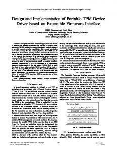
2.1 ActiveX based Device Driver Model Fig.1 shows the flow of data from application to the PLC Hardware. Application block may be a Form in VB or a Dialog box in VC++. Depending upon the requirement, the user can design the application window with the help of ActiveX Component. The generated application has various ActiveX property values. These values are also called as properties are then passed to device with the help of device driver. Application
Application
Application
ActiveX Component
ActiveX Component
ActiveX Component
Driver.dll
MFC Library
Device Driver
Win32 API Computer Hardware Programmable Logic Controller
Fig.1. Data flow scenario The device driver block consists of driver file as *.dll, MFC library and windows32 Application Programming Interface (API). The driver *.dll is written in MFC. This file communicates with the computer hardware with the help of Win32 API. There are various functions which is written in driver *.dll, like open driver, close driver, configuring serial ports, configuring time-outs, writing to a serial port, reading from a serial port and closing a serial Port. Win32 API includes hundreds of functions that an application can call to perform various tasks such as creating a window, drawing a line, and performing file input and output. 2.2 Driver functionality The drivers (*.dll) are meant for communication between the host computer and PLC Device. It provides the following service and functions: • Device function: initializes and configures the hardware and software
•
• •
Analog Input function: converts single and multiple channel Analog to Digital Converter (A/D) Analog Output function: converts a single And multiple channel Digital to Analog Converter (D/A) Digital I/O function: controls digital I/O for specified channel Port I/O function: controls port I/O
2.3 Driver Component description Applications include user programs, configuration utilities and application software that use the driver. The driver system prepares for communication between the host computer and PLC. Upon receiving a request from the application, it provides the following services and functions. 1. Device function: initializes and configures the hardware and software. 2. Analog input function: converts single and multiple-channel A/D 3. Analog output function: converts single D/A 4. Digital I/O function: controls digital I/O for the specified channel. 5. Port I/O function: controls port I/O. 6. Communication port function: operates the communication port. The Registry/Configuration file stores data about hardware settings. These data will be used for the driver during I/O access. 2.4 Creating ActiveX Component While writing the code for ActiveX the authors had a problem of initializing user defined properties. Two different methods which are used in general are either Get/Set method or dynamic property enumeration method. To overcome this difficulty, it was decided to use the combination of both the methods. The difficulty ultimately was overcome. The dynamic property enumeration is the most flexible type of property enumeration and is perfect for situations where one needs to restrict the data that can be entered into a property but are unable to determine the valid values until the runtime. However, the dynamic property enumeration using MFC requires the implementation of three methods listed below for control, viz. 1. 2. 3.
OnGetPredefinedStrings, OnGetPredefinedValue OnGetDisplayString
Component selection
Fig.2. Importing ActiveX component to the user applications
Component selection
Component properties
Fig. 3 Integrating ActiveX component in the user application
Fig.2 shows the screen shot of importing newly created ActiveX component to the user applications. The application window was created using Visual Basic (VB 6.0). As per user requirement he can use multiple controls. These controls are added to the applications just by dragging the component on application window. After selecting such component the hardware is then initialized. 2.5 Integrating ActiveX component Once an ActiveX component is selected one can create as many instance by dragging and
dropping controls on VB form as per the requirement. When user selects any property, the property window gets drop down list of specified values. The drop down list contains a set of values specified by the designer to restrict the user. All property related to the component can be changed by user just by clicking on property window of ActiveX component as shown in Fig.3. Whenever the user wants to change the property of any component, this new value is checked and specified parameter is set in device driver through respective ActiveX component.
Fig.4. User defined application window for Case.1
Fig.5. User defined application window for Case.2
3. Applications 3.1.Case:1 Fig.4 shows the user defined application window designed for the following specification: • 8 Analog Input Channels • 8 Analog Output Channels • 8 Digital Input Channels • 8 Digital Output Channels As shown in Fig.4, the window has eight buttons provided for analog inputs and outputs as well as for digital inputs and outputs. During run time, if the user presses any one of the button from analog section and can watch the voltage or set the corresponding voltage as per the requirement. Similarly, if the user presses any one of the button from digital section he can watch or set digital channel. 3.2.Case:2 Fig.5 shows the user defined application window designed for the following specification: • 4 Analog Input Channels • 5 Analog Output Channels • 6 Digital Input Channels • 8 Digital Output Channels The run time operations are same that of case.1 4.Conclusion The ADDM provides new levels of hardware innovation, dynamic device and resource configuration. Also it supports for multiple host Operating Systems, interface flexibility and extensibility, driver reuse, and ease of development. The ADDM is intended for powerful and flexible input/ output services The ADDM represents an innovative advance in I/0 software technology. Therefore, combining the power of component objects method with the flexibility of frameworks, the ADDM gives us the benefits of rapid I/0 software development, broad-based compatibility and portability, plugand-play hardware configuration and the reliability of user-mode I/O software. The user can tailor any type of applications for PLC with the help of ADDM. The paper has highlighted the idea of creating user defined device driver with a greater simplicity. Beginner in PLC programming can very well build a driver application as per his need. The ADDM ultimately makes development, debugging, and maintenance easier and more efficient. Developers can write I/O software which is potentially compatible across a wide range of OS and hardware platforms.
5. References 1. A. Alheraish, W. Alomar, and M. Abu-Al-Ela “Programmable logic controller system for controlling andmonitoring home application using mobile network ”, Electrical Engineering Dept. King Saud University , Proc. of Instrumentation and Measurement Technology Conference (IMTC 2006 ) Sorrento, Italy, 24-27April 2006. 2. Xu De, Sun Tongjing, Chen Guiyou. “The Application Technology of Programmable Controller”, 2nd Edition. Shan Dong Science and Technology Publishing House, ShanDong, 2002. 3. Jose Roger_Folch, Juan Pérez, Manuel Pineda, and Rubén Puche, “Graphical Development of Software for Programmable Logic Controllers”, Department of Electrical Engineering, Universidad Politécnica de Valencia, Valencia, Spain. 4. M. HBonfeH and C. Fantuzzi, “Object-oriented approach to plc software design for a manufacture machine using iec61131-3 norm languages”, in Proc. of IEEE/ASME Int. Conf. on Advanced Intelligent Mechatronics, vol. 2, pp. 787792, 2001. 5. Bhupender Parashar and Gulshan Taneja, “Reliability and Profit Evaluation of a PLC Hot Standby System Based on a Master-Slave Concept and Two Types of Repair Facilities ”, IEEE transactions on reliability, vol. 56, no. 3, Sept. 2007. 6. V. HVyatkin, H J. H. HChristensen, and H J. M. Lasta, “OONEIDA: an open, object oriented knowledge economy for intelligent industrial automation”, IEEE Trans. Ind. Informat., vol. 1, no. 1, pp. 4-17, 2005. 7. T. Facchinetti, G. Buttazzo, M. Marinoni, and G. Guidi, “Non-preemptive interrupt scheduling for safe reuse of legacy drivers in real-time systems”. In Proc. 17th IEEE Euromicro Conference on Real-Time Systems, Palma de Mallorca, July 2005.


![[PDF] ActiveX Sourcebook: Build an ActiveX-Based Web Site - Full ...](https://m.moam.info/img/260x300/pdf-activex-sourcebook-build-an-activex-based-web-_6477b82e097c474e708c0427.jpg)