Apr 1, 2008 ... Step 2: Configure PAT on R2 using the serial 0/0/1 interface public IP address. ...
NAT pool MY-NAT-POOL command to allow for more than six ...
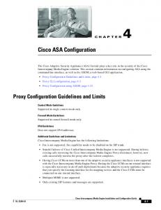
Activity 7.4.1: Basic DHCP and NAT Configuration Topology Diagram
Addressing Table Device
R1
R2
ISP
Interface
IP Address
Subnet Mask
S0/0/0
10.1.1.1
255.255.255.252
Fa0/0
192.168.10.1
255.255.255.0
Fa0/1
192.168.11.1
255.255.255.0
S0/0/0
10.1.1.2
255.255.255.252
S0/0/1
209.165.200.225
255.255.255.252
Fa0/0
192.168.20.1
255.255.255.0
S0/0/1
209.165.200.226
255.255.255.252
Learning Objectives Upon completion of this lab, you will be able to: •
Prepare the network
•
Perform basic router configurations
•
Configure a Cisco IOS DHCP server
•
Configure static and default routing
•
Configure static NAT
•
Configure dynamic NAT with a pool of addresses
•
Configure NAT overload
All contents are Copyright © 1992–2007 Cisco Systems, Inc. All rights reserved. This document is Cisco Public Information.
Page 1 of 12
CCNA Exploration Accessing the WAN: IP Addressing Services
PT Activity 7.4.1: Basic DHCP and NAT Configuration
Scenario In this lab, you will configure the DHCP and NAT IP services. One router is the DHCP server. The other router forwards DHCP requests to the server. You will also configure both static and dynamic NAT configurations, including NAT overload. When you have completed the configurations, verify the connectivity between the inside and outside addresses.
Task 1: Perform Basic Router Configurations Configure the R1, R2, and ISP routers according to the following guidelines: •
Configure the device hostname.
•
Disable DNS lookup.
•
Configure a privileged EXEC mode password.
•
Configure a message-of-the-day banner.
•
Configure a password for the console connections.
•
Configure a password for all vty connections.
•
Configure IP addresses on all routers. The PCs receive IP addressing from DHCP later in the activity.
•
Enable OSPF with process ID 1 on R1 and R2. Do not advertise the 209.165.200.224/27 network.
Task 2: Configure a Cisco IOS DHCP Server Step 1: Exclude statically assigned addresses. The DHCP server assumes that all IP addresses in a DHCP address pool subnet are available for assigning to DHCP clients. You must specify the IP addresses that the DHCP server should not assign to clients. These IP address are usually static addresses reserved for the router interface, switch management IP address, servers, and local network printer. The ip dhcp excluded-address command prevents the router from assigning IP addresses within the configured range. The following commands exclude the first 10 IP addresses from each pool for the LANs attached to R1. These addresses will not be assigned to any DHCP clients. R1(config)#ip dhcp excluded-address 192.168.10.1 192.168.10.10 R1(config)#ip dhcp excluded-address 192.168.11.1 192.168.11.10 Step 2: Configure the pool. Create the DHCP pool using the ip dhcp pool command and name it R1Fa0. R1(config)#ip dhcp pool R1Fa0 Specify the subnet to use when assigning IP addresses. DHCP pools automatically associate with an interface based on the network statement. The router now acts as a DHCP server, handing out addresses in the 192.168.10.0/24 subnet starting with 192.168.10.1. R1(dhcp-config)#network 192.168.10.0 255.255.255.0 Configure the default router and domain name server for the network. Clients receive these settings via DHCP, along with an IP address. R1(dhcp-config)#dns-server 192.168.11.5 R1(dhcp-config)#default-router 192.168.10.1 Note: There is not a DNS server at 192.168.11.5. You are configuring the command for practice only. All contents are Copyright © 1992–2007 Cisco Systems, Inc. All rights reserved. This document is Cisco Public Information.
Page 2 of 12
CCNA Exploration Accessing the WAN: IP Addressing Services
PT Activity 7.4.1: Basic DHCP and NAT Configuration
R1(config)#ip dhcp pool R1Fa1 R1(dhcp-config)#network 192.168.11.0 255.255.255.0 R1(dhcp-config)#dns-server 192.168.11.5 R1(dhcp-config)#default-router 192.168.11.1 Step 3: Verify the DHCP configuration. You can verify the DHCP server configuration in several different ways. The most basic way is to configure a host on the subnet to receive an IP address via DHCP. You can then issue commands on the router to get more information. The show ip dhcp binding command provides information on all currently assigned DHCP addresses. For instance, the following output shows that the IP address 192.168.10.11 has been assigned to MAC address 3031.632e.3537.6563. The IP lease expires on September 14, 2007 at 7:33 pm. R1#show ip dhcp binding IP address Client-ID/ Lease expiration Type Hardware address 192.168.10.11 0007.EC66.8752 -- Automatic 192.168.11.11 00E0.F724.8EDA -- Automatic
Task 3: Configure Static and Default Routing ISP uses static routing to reach all networks beyond R2. However, R2 translates private addresses into public addresses before sending traffic to ISP. Therefore, ISP must be configured with the public addresses that are part of the NAT configuration on R2. Enter the following static route on ISP: ISP(config)#ip route 209.165.200.240 255.255.255.240 serial 0/0/1 This static route includes all addresses assigned to R2 for public use. Configure a default route on R2 and propagate the route in OSPF. R2(config)#ip route 0.0.0.0 0.0.0.0 209.165.200.226 R2(config)#router ospf 1 R2(config-router)#default-information originate Allow a few seconds for R1 to learn the default route from R2 and then check the R1 routing table. Alternatively, you can clear the routing table with the clear ip route * command. A default route pointing to R2 should appear in the R1 routing table. From R1, ping the serial 0/0/1 interface on R2 (209.165.200.225). The pings should be successful. Troubleshoot if the pings fail.
Task 4: Configure Static NAT Step 1: Statically map a public IP address to a private IP address. The inside server attached to R2 is accessible by outside hosts beyond ISP. Statically assign the public IP address 209.165.200.254 as the address for NAT to use to map packets to the private IP address of the inside server at 192.168.20.254. R2(config)#ip nat inside source static 192.168.20.254 209.165.200.254 Step 2: Specify inside and outside NAT interfaces. Before NAT can work, you must specify which interfaces are inside and which interfaces are outside. R2(config)#interface serial 0/0/1 R2(config-if)#ip nat outside R2(config-if)#interface fa0/0 R2(config-if)#ip nat inside
All contents are Copyright © 1992–2007 Cisco Systems, Inc. All rights reserved. This document is Cisco Public Information.
Page 3 of 12
CCNA Exploration Accessing the WAN: IP Addressing Services
PT Activity 7.4.1: Basic DHCP and NAT Configuration
Step 3: Verify the static NAT configuration. From ISP, ping the public IP address 209.165.200.254.
Task 5: Configure Dynamic NAT with a Pool of Addresses While static NAT provides a permanent mapping between an internal address and a specific public address, dynamic NAT maps private IP addresses to public addresses. These public IP addresses come from a NAT pool. Step 1: Define a pool of global addresses. Create a pool of addresses to which matched source addresses are translated. The following command creates a pool named MY-NAT-POOL that translates matched addresses to an available IP address in the 209.165.200.241 - 209.165.200.246 range. R2(config)#ip nat pool MY-NAT-POOL 209.165.200.241 209.165.200.246 netmask 255.255.255.248 Step 2: Create a standard access control list to identify which inside addresses are translated. R2(config)#ip access-list extended NAT R2(config-std-nacl)#permit ip 192.168.10.0 0.0.0.255 any R2(config-std-nacl)#permit ip 192.168.11.0 0.0.0.255 any Step 3: Establish dynamic source translation by binding the pool with the access control list. A router can have more than one NAT pool and more than one ACL. The following command tells the router which address pool to use to translate hosts that are allowed by the ACL. R2(config)#ip nat inside source list NAT pool MY-NAT-POOL Step 4: Specify inside and outside NAT interfaces. You have already specified the inside and outside interfaces for your static NAT configuration. Now add the serial interface linked to R1 as an inside interface. R2(config)#interface serial 0/0/0 R2(config-if)#ip nat inside Step 5: Verify the configuration. Ping ISP from PC1 and PC2. Then use the show ip nat translations command on R2 to verify NAT. R2#show ip nat translations Pro Inside global Inside local --- 209.165.200.241 192.168.10.11 --- 209.165.200.242 192.168.11.11 --- 209.165.200.254 192.168.20.254
Outside local -------
Outside global -------
Task 6: Configure NAT Overload In the previous example, what would happen if you needed more than the six public IP addresses that the pool allows? By tracking port numbers, NAT overloading allows multiple inside users to reuse a public IP address. In this task, you will remove the pool and mapping statement configured in the previous task. Then you will configure NAT overload on R2 so that all internal IP addresses are translated to the R2 S0/0/1 address when connecting to any outside device.
All contents are Copyright © 1992–2007 Cisco Systems, Inc. All rights reserved. This document is Cisco Public Information.
Page 4 of 12
CCNA Exploration Accessing the WAN: IP Addressing Services
PT Activity 7.4.1: Basic DHCP and NAT Configuration
Step 1: Remove the NAT pool and mapping statement. Use the following commands to remove the NAT pool and the map to the NAT ACL. R2(config)#no ip nat pool MY-NAT-POOL 209.165.200.241 209.165.200.246 netmask 255.255.255.248 R2(config)#no ip nat inside source list NAT pool MY-NAT-POOL If you receive the following message, clear your NAT translations. %Pool MY-NAT-POOL in use, cannot destroy R2#clear ip nat translation * Step 2: Configure PAT on R2 using the serial 0/0/1 interface public IP address. The configuration is similar to dynamic NAT, except that instead of a pool of addresses, the interface keyword is used to identify the outside IP address. Therefore, no NAT pool is defined. The overload keyword enables the addition of the port number to the translation. Because you already configured an ACL to identify which inside IP addresses to translate as well as which interfaces are inside and outside, you only need to configure the following: R2(config)#ip nat inside source list NAT interface S0/0/1 overload Step 3: Verify the configuration. Ping ISP from PC1 and PC2. Then use the show ip nat translations command on R2 to verify NAT. R2#show ip nat translations Pro Inside global Inside local icmp 209.165.200.225:3 192.168.10.11:3 209.165.200.226:3 icmp 209.165.200.225:1024192.168.11.11:3 209.165.200.226:1024 --- 209.165.200.254 192.168.20.254
Outside local 209.165.200.226:3
Outside global
209.165.200.226:3 ---
---
Note: In the previous task, you could have added the keyword overload to the ip nat inside source list NAT pool MY-NAT-POOL command to allow for more than six concurrent users.
Task 7: Document the Network On each router, issue the show run command and capture the configurations.
Task 1: Prepare the Network Step 1: Cable a network that is similar to the one in the topology diagram. You can use any current router in your lab as long as it has the required interfaces shown in the topology. Note: If you use a 1700, 2500, or 2600 series router, the router outputs and interface descriptions may look different. Step 2: Clear all existing configurations on the routers.
Task 2: Perform Basic Router Configurations Configure the R1, R2, and ISP routers according to the following guidelines: All contents are Copyright © 1992–2007 Cisco Systems, Inc. All rights reserved. This document is Cisco Public Information.
Page 5 of 12
CCNA Exploration Accessing the WAN: IP Addressing Services
PT Activity 7.4.1: Basic DHCP and NAT Configuration
•
Configure the device hostname.
•
Disable DNS lookup.
•
Configure a privileged EXEC mode password.
•
Configure a message-of-the-day banner.
•
Configure a password for the console connections.
•
Configure a password for all vty connections.
•
Configure IP addresses on all routers. The PCs receive IP addressing from DHCP later in the lab.
•
Enable OSPF with process ID 1 on R1 and R2. Do not advertise the 209.165.200.224/27 network.
Note: Instead of attaching a server to R2, you can configure a loopback interface on R2 to use the IP address 192.168.20.254/24. If you do this, you do not need to configure the Fast Ethernet interface.
Task 3: Configure a Cisco IOS DHCP Server Cisco IOS software supports a DHCP server configuration called Easy IP. The goal for this lab is to have devices on the networks 192.168.10.0/24 and 192.168.11.0/24 request IP addresses via DHCP from R2. Step 1. Exclude statically assigned addresses. The DHCP server assumes that all IP addresses in a DHCP address pool subnet are available for assigning to DHCP clients. You must specify the IP addresses that the DHCP server should not assign to clients. These IP addresses are usually static addresses reserved for the router interface, switch management IP address, servers, and local network printer. The ip dhcp excluded-address command prevents the router from assigning IP addresses within the configured range. The following commands exclude the first 10 IP addresses from each pool for the LANs attached to R1. These addresses will not be assigned to any DHCP clients. R2(config)#ip dhcp excluded-address 192.168.10.1 192.168.10.10 R2(config)#ip dhcp excluded-address 192.168.11.1 192.168.11.10 Step 2. Configure the pool. Create the DHCP pool using the ip dhcp pool command and name it R1Fa0. R2(config)#ip dhcp pool R1Fa0 Specify the subnet to use when assigning IP addresses. DHCP pools automatically associate with an interface based on the network statement. The router now acts as a DHCP server, handing out addresses in the 192.168.10.0/24 subnet starting with 192.168.10.1. R2(dhcp-config)#network 192.168.10.0 255.255.255.0 Configure the default router and domain name server for the network. Clients receive these settings via DHCP, along with an IP address. R2(dhcp-config)#dns-server 192.168.11.5 R2(dhcp-config)#default-router 192.168.10.1 Note: There is not a DNS server at 192.168.11.5. You are configuring the command for practice only. Because devices from the network 192.168.11.0/24 also request addresses from R2, a separate pool must be created to serve devices on that network. The commands are similar to the commands shown above: R2(config)#ip dhcp pool R1Fa1 R2(dhcp-config)#network 192.168.11.0 255.255.255.0 All contents are Copyright © 1992–2007 Cisco Systems, Inc. All rights reserved. This document is Cisco Public Information.
Page 6 of 12
CCNA Exploration Accessing the WAN: IP Addressing Services
PT Activity 7.4.1: Basic DHCP and NAT Configuration
R2(dhcp-config)#dns-server 192.168.11.5 R2(dhcp-config)#default-router 192.168.11.1 Step 3. Configure a helper address. Network services such as DHCP rely on Layer 2 broadcasts to function. When the devices providing these services exist on a different subnet than the clients, they cannot receive the broadcast packets. Because the DHCP server and the DHCP clients are not on the same subnet, configure R1 to forward DHCP broadcasts to R2, which is the DHCP server, using the ip helper-address interface configuration command. Notice that ip helper-address must be configured on each interface involved. R1(config)#interface fa0/0 R1(config-if)#ip helper-address 10.1.1.2 R1(config)#interface fa0/1 R1(config-if)#ip helper-address 10.1.1.2 Step 4. Verify the DHCP configuration. You can verify the DHCP server configuration in several different ways. The most basic way is to configure a host on the subnet to receive an IP address via DHCP. You can then issue commands on the router to get more information. The show ip dhcp binding command provides information on all currently assigned DHCP addresses. For instance, the following output shows that the IP address 192.168.10.11 has been assigned to MAC address 3031.632e.3537.6563. The IP lease expires on September 14, 2007 at 7:33 p.m. R1#show ip dhcp binding Bindings from all pools not associated with VRF: IP address Client-ID/ Lease expiration Hardware address/ User name 192.168.10.11 0063.6973.636f.2d30. Sep 14 2007 07:33 PM 3031.632e.3537.6563. 2e30.3634.302d.566c. 31
Type
Automatic
The show ip dhcp pool command displays information on all currently configured DHCP pools on the router. In this output, the pool R1Fa0 is configured on R1. One address has been leased from this pool. The next client to request an address will receive 192.168.10.12. R2#show ip dhcp pool Pool R1Fa0 : Utilization mark (high/low) : 100 / 0 Subnet size (first/next) : 0 / 0 Total addresses : 254 Leased addresses : 1 Pending event : none 1 subnet is currently in the pool : Current index IP address range 192.168.10.12 192.168.10.1 - 192.168.10.254
Leased addresses 1
The debug ip dhcp server events command can be extremely useful when troubleshooting DHCP leases with a Cisco IOS DHCP server. The following is the debug output on R1 after connecting a host. Notice that the highlighted portion shows DHCP giving the client an address of 192.168.10.12 and mask of 255.255.255.0 *Sep 13 21:04:18.072: DHCPD: Sending notification of DISCOVER: *Sep 13 21:04:18.072: DHCPD: htype 1 chaddr 001c.57ec.0640 All contents are Copyright © 1992–2007 Cisco Systems, Inc. All rights reserved. This document is Cisco Public Information.
Page 7 of 12
CCNA Exploration Accessing the WAN: IP Addressing Services
PT Activity 7.4.1: Basic DHCP and NAT Configuration
*Sep 13 21:04:18.072: DHCPD: remote id 020a0000c0a80b01010000000000 *Sep 13 21:04:18.072: DHCPD: circuit id 00000000 *Sep 13 21:04:18.072: DHCPD: Seeing if there is an internally specified pool class: *Sep 13 21:04:18.072: DHCPD: htype 1 chaddr 001c.57ec.0640 *Sep 13 21:04:18.072: DHCPD: remote id 020a0000c0a80b01010000000000 *Sep 13 21:04:18.072: DHCPD: circuit id 00000000 *Sep 13 21:04:18.072: DHCPD: there is no address pool for 192.168.11.1. *Sep 13 21:04:18.072: DHCPD: Sending notification of DISCOVER: R1# *Sep 13 21:04:18.072: DHCPD: htype 1 chaddr 001c.57ec.0640 *Sep 13 21:04:18.072: DHCPD: remote id 020a0000c0a80a01000000000000 *Sep 13 21:04:18.072: DHCPD: circuit id 00000000 *Sep 13 21:04:18.072: DHCPD: Seeing if there is an internally specified pool class: *Sep 13 21:04:18.072: DHCPD: htype 1 chaddr 001c.57ec.0640 *Sep 13 21:04:18.072: DHCPD: remote id 020a0000c0a80a01000000000000 *Sep 13 21:04:18.072: DHCPD: circuit id 00000000 R1# *Sep 13 21:04:20.072: DHCPD: Adding binding to radix tree (192.168.10.12) *Sep 13 21:04:20.072: DHCPD: Adding binding to hash tree *Sep 13 21:04:20.072: DHCPD: assigned IP address 192.168.10.12 to client 0063.6973.636f.2d30.3031.632e.3537.6563.2e30.3634.302d.566c.31. *Sep 13 21:04:20.072: DHCPD: Sending notification of ASSIGNMENT: *Sep 13 21:04:20.072: DHCPD: address 192.168.10.12 mask 255.255.255.0 *Sep 13 21:04:20.072: DHCPD: htype 1 chaddr 001c.57ec.0640 *Sep 13 21:04:20.072: DHCPD: lease time remaining (secs) = 86400 *Sep 13 21:04:20.076: DHCPD: Sending notification of ASSIGNMENT: *Sep 13 21:04:20.076: DHCPD: address 192.168.10.12 mask 255.255.255.0 R1# *Sep 13 21:04:20.076: DHCPD: htype 1 chaddr 001c.57ec.0640 *Sep 13 21:04:20.076: DHCPD: lease time remaining (secs) = 86400
Task 4: Configure Static and Default Routing ISP uses static routing to reach all networks beyond R2. However, R2 translates private addresses into public addresses before sending traffic to ISP. Therefore, ISP must be configured with the public addresses that are part of the NAT configuration on R2. Enter the following static route on ISP: ISP(config)#ip route 209.165.200.240 255.255.255.240 serial 0/0/1 This static route includes all addresses assigned to R2 for public use. Configure a default route on R2 and propagate the route in OSPF. R2(config)#ip route 0.0.0.0 0.0.0.0 209.165.200.225 R2(config)#router ospf 1 R2(config-router)#default-information originate Allow a few seconds for R1 to learn the default route from R2 and then check the R1 routing table. Alternatively, you can clear the routing table with the clear ip route * command. A default route pointing to R2 should appear in the R1 routing table. From R1, ping the serial 0/0/1 interface on R2 (209.165.200.226). The pings should be successful. Troubleshoot if the pings fail.
All contents are Copyright © 1992–2007 Cisco Systems, Inc. All rights reserved. This document is Cisco Public Information.
Page 8 of 12
CCNA Exploration Accessing the WAN: IP Addressing Services
PT Activity 7.4.1: Basic DHCP and NAT Configuration
Task 5: Configure Static NAT Step 1. Statically map a public IP address to a private IP address. The inside server attached to R2 is accessible by outside hosts beyond ISP. Statically assign the public IP address 209.165.200.254 as the address for NAT to use to map packets to the private IP address of the inside server at 192.168.20.254. R2(config)#ip nat inside source static 192.168.20.254 209.165.200.254 Step 2. Specify inside and outside NAT interfaces. Before NAT can work, you must specify which interfaces are inside and which interfaces are outside. R2(config)#interface serial 0/0/1 R2(config-if)#ip nat outside R2(config-if)#interface fa0/0 R2(config-if)#ip nat inside Note: If using a simulated inside server, assign the ip nat inside command to the loopback interface. Step 3. Verify the static NAT configuration. From ISP, ping the public IP address 209.165.200.254.
Task 6: Configure Dynamic NAT with a Pool of Addresses While static NAT provides a permanent mapping between an internal address and a specific public address, dynamic NAT maps private IP addresses to public addresses. These public IP addresses come from a NAT pool. Step 1. Define a pool of global addresses. Create a pool of addresses to which matched source addresses are translated. The following command creates a pool named MY-NAT-POOL that translates matched addresses to an available IP address in the 209.165.200.241–209.165.200.246 range. R2(config)#ip nat pool MY-NAT-POOL 209.165.200.241 209.165.200.246 netmask 255.255.255.248 Step 2. Create an extended access control list to identify which inside addresses are translated. R2(config)#ip access-list extended NAT R2(config-ext-nacl)#permit ip 192.168.10.0 0.0.0.255 any R2(config-ext-nacl)#permit ip 192.168.11.0 0.0.0.255 any Step 3. Establish dynamic source translation by binding the pool with the access control list. A router can have more than one NAT pool and more than one ACL. The following command tells the router which address pool to use to translate hosts that are allowed by the ACL. R2(config)#ip nat inside source list NAT pool MY-NAT-POOL Step 4. Specify inside and outside NAT interfaces. You have already specified the inside and outside interfaces for your static NAT configuration. Now add the serial interface linked to R1 as an inside interface. R2(config)#interface serial 0/0/0 R2(config-if)#ip nat inside
All contents are Copyright © 1992–2007 Cisco Systems, Inc. All rights reserved. This document is Cisco Public Information.
Page 9 of 12
CCNA Exploration Accessing the WAN: IP Addressing Services
PT Activity 7.4.1: Basic DHCP and NAT Configuration
Step 5. Verify the configuration. Ping ISP from PC1 or the Fast Ethernet interface on R1 using extended ping. Then use the show ip nat translations and show ip nat statistics commands on R2 to verify NAT. R2#show ip nat translations Pro Inside global Inside local icmp 209.165.200.241:4 192.168.10.1:4 --- 209.165.200.241 192.168.10.1 --- 209.165.200.254 192.168.20.254
Outside local 209.165.200.226:4 -----
Outside global 209.165.200.226:4 -----
R2#show ip nat statistics Total active translations: 2 (1 static, 1 dynamic; 0 extended) Outside interfaces: Serial0/0/1 Inside interfaces: Serial0/0/0, Loopback0 Hits: 23 Misses: 3 CEF Translated packets: 18, CEF Punted packets: 0 Expired translations: 3 Dynamic mappings: -- Inside Source [Id: 1] access-list NAT pool MY-NAT-POOL refcount 1 pool MY-NAT-POOL: netmask 255.255.255.248 start 209.165.200.241 end 209.165.200.246 type generic, total addresses 6, allocated 1 (16%), misses 0 Queued Packets: 0 To troubleshoot issues with NAT, you can use the debug ip nat command. Turn on NAT debugging and repeat the ping from PC1. R2#debug ip nat IP NAT debugging is on R2# *Sep 13 21:15:02.215: NAT*: *Sep 13 21:15:02.231: NAT*: *Sep 13 21:15:02.247: NAT*: *Sep 13 21:15:02.263: NAT*: *Sep 13 21:15:02.275: NAT*: *Sep 13 21:15:02.291: NAT*: *Sep 13 21:15:02.307: NAT*: *Sep 13 21:15:02.323: NAT*: *Sep 13 21:15:02.335: NAT*: *Sep 13 21:15:02.351: NAT*: R2#
s=192.168.10.11->209.165.200.241, d=209.165.200.226 s=209.165.200.226, d=209.165.200.241->192.168.10.11 s=192.168.10.11->209.165.200.241, d=209.165.200.226 s=209.165.200.226, d=209.165.200.241->192.168.10.11 s=192.168.10.11->209.165.200.241, d=209.165.200.226 s=209.165.200.226, d=209.165.200.241->192.168.10.11 s=192.168.10.11->209.165.200.241, d=209.165.200.226 s=209.165.200.226, d=209.165.200.241->192.168.10.11 s=192.168.10.11->209.165.200.241, d=209.165.200.226 s=209.165.200.226, d=209.165.200.241->192.168.10.11
Task 7: Configure NAT Overload In the previous example, what would happen if you needed more than the six public IP addresses that the pool allows? __________________________________________________________________________________ The seventh and subsequent users would not be able to access destinations beyond R2. By tracking port numbers, NAT overloading allows multiple inside users to reuse a public IP address.
All contents are Copyright © 1992–2007 Cisco Systems, Inc. All rights reserved. This document is Cisco Public Information.
Page 10 of 12
[25] [25] [26] [26] [27] [27] [28] [28] [29] [29]
CCNA Exploration Accessing the WAN: IP Addressing Services
PT Activity 7.4.1: Basic DHCP and NAT Configuration
In this task, you will remove the pool and mapping statement configured in the previous task. Then you will configure NAT overload on R2 so that all internal IP addresses are translated to the R2 S0/0/1 address when connecting to any outside device. Step 1. Remove the NAT pool and mapping statement. Use the following commands to remove the NAT pool and the map to the NAT ACL. R2(config)#no ip nat pool MY-NAT-POOL 209.165.200.241 209.165.200.246 netmask 255.255.255.248 R2(config)#no ip nat inside source list NAT pool MY-NAT-POOL If you receive the following message, clear your NAT translations. %Pool MY-NAT-POOL in use, cannot destroy R2#clear ip nat translation * Step 2. Configure PAT on R2 using the serial 0/0/1 interface public IP address. The configuration is similar to dynamic NAT, except that instead of a pool of addresses, the interface keyword is used to identify the outside IP address. Therefore, no NAT pool is defined. The overload keyword enables the addition of the port number to the translation. Because you already configured an ACL to identify which inside IP addresses to translate as well as which interfaces are inside and outside, you only need to configure the following: R2(config)#ip nat inside source list NAT interface S0/0/1 overload Step 3. Verify the configuration. Ping ISP from PC1 or the Fast Ethernet interface on R1 using extended ping. Then use the show ip nat translations and show ip nat statistics commands on R2 to verify NAT. R2#show ip nat translations Pro Inside global Inside local icmp 209.165.200.225:6 192.168.10.11:6 --- 209.165.200.254 192.168.20.254
Outside local 209.165.200.226:6 ---
Outside global 209.165.200.226:6 ---
R2#show ip nat statistics Total active translations: 2 (1 static, 1 dynamic; 1 extended) Outside interfaces: Serial0/0/1 Inside interfaces: Serial0/0/0, Loopback0 Hits: 48 Misses: 6 CEF Translated packets: 46, CEF Punted packets: 0 Expired translations: 5 Dynamic mappings: -- Inside Source [Id: 2] access-list NAT interface Serial0/0/1 refcount 1 Queued Packets: 0 Note: In the previous task, you could have added the keyword overload to the ip nat inside source list NAT pool MY-NAT-POOL command to allow for more than six concurrent users.
Task 8: Document the Network On each router, issue the show run command and capture the configurations.
All contents are Copyright © 1992–2007 Cisco Systems, Inc. All rights reserved. This document is Cisco Public Information.
Page 11 of 12
CCNA Exploration Accessing the WAN: IP Addressing Services
PT Activity 7.4.1: Basic DHCP and NAT Configuration
Task 9: Clean Up Erase the configurations and reload the routers. Disconnect and store the cabling. For PC hosts that are normally connected to other networks, such as the school LAN or the Internet, reconnect the appropriate cabling and restore the TCP/IP settings.
All contents are Copyright © 1992–2007 Cisco Systems, Inc. All rights reserved. This document is Cisco Public Information.
Page 12 of 12


![[MS-DHCPE]: Dynamic Host Configuration Protocol (DHCP ...](https://m.moam.info/img/260x300/ms-dhcpe-dynamic-host-configuration-protocol-dhcp-_5a12d2421723dd5525c9aa56.jpg)