JOURNAL OF AEROSPACE COMPUTING, INFORMATION, AND COMMUNICATION Vol. 6, May 2009
Ad Hoc Wireless Networking and Shared Computation for Autonomous Multirobot Systems Riccardo Bevilacqua∗ , Jason S. Hall† , James Horning‡ , and Marcello Romano§ Naval Postgraduate School, Monterey, CA, 93943 DOI: 10.2514/1.40734
A wireless ad hoc network is introduced that enables inter-robot communication and shared computation among multiple robots with PC/104-based single board computers running the real-time application interface patched Linux operating system. Through the use of IEEE 802.11 ad hoc technology and User Datagram Protocol, each robot is able to exchange data without the need of a centralized router or wireless access point. The paper presents three key aspects of this novel architecture to include: 1) procedures to install the real-time application interface patched operating system and wireless ad hoc communication protocol on a multiple robot system; 2) development of a Simulink® library to enable intercommunication among robots and provide the requisite software-hardware interfaces for the onboard sensor suite and actuator packages; 3) methods to rapidly generate and deploy real-time executables using Mathwork’s Real-Time Workshop™ to enable an autonomous robotic system. Experimental test results from the Spacecraft Robotics Laboratory at the Naval Postgraduate School are presented which demonstrate negligible network latencies and real-time distributed computing capability on the Autonomous Spacecraft Assembly Test Bed. A complete manual is also included to replicate the network and software infrastructures described in this work. Also, the developed Simulink® library can be requested from the authors.
Nomenclature CF COTS DoF FOG FPGA GNC GUI
compact flash (removable memory drive) commercial off-the-shelf degrees of freedom fiber optic gyro field programmable gate array guidance, navigation, and control graphical user interface
Received 1 September 2008; revision received 26 January 2009; accepted for publication 9 February 2009. This material is declared a work of the U.S. Government and is not subject to copyright protection in the United States. Copies of this paper may be made for personal or internal use, on condition that the copier pay the $10.00 per-copy fee to the Copyright Clearance Center, Inc., 222 Rosewood Drive, Danvers, MA 01923; include the code 1542-9423/09 $10.00 in correspondence with the CCC. This material is a work of the U.S. Government and is not subject to copyright protection in the United States. ∗ Ph.D., Research Associate, Department of Mechanical and Astronautical Engineering, Code AA/RB, 699 Dyer Rd. Email:
[email protected]. AIAA Member. † Ph.D. Candidate, Department of Mechanical and Astronautical Engineering, Code AA/JH, 699 Dyer Rd. Email:
[email protected]. AIAA Member. ‡ Research Associate, Space Systems Academic Group, Code Sp/Jh, 777 Dyer Rd., email:
[email protected]. AIAA Member. § Assistant Professor, Department of Mechanical and Astronautical Engineering, Code MAE/MR, 700 Dyer Rd. Email:
[email protected]. AIAA Senior Member.
328
BEVILACQUA ET AL.
IP MAG N NPS OS PD PWM RTAI SRL UDP
R
internet protocol (IP address: a unique address that certain electronic devices use to identify and communicate with each other on a computer network using the Internet Protocol standard) magnetometer number of robots Naval Postgraduate School operating system proportional derivative pulse width modulation real-time application interface Spacecraft Robotics Laboratory user datagram protocol
I.
Introduction
EAL-TIME control and relative navigation of multiple agent systems is a widely studied topic with respect to autonomous computing and telecommunication [1–6]. Many multi-robot space missions [6–8] demand autonomous onboard processing capability, which is critical both for planetary exploration, and on-orbit maneuvering when the up/down link capabilities may be limited [6–9]. Our primary research focus is on autonomous spacecraft proximity maneuvers as orbital rendezvous and assembly [10–14]. The scalability of both the computation environment and the communication infrastructure is an additional research focus for multiple autonomous vehicle systems. The use of wireless ad hoc networking has become increasingly important in various technical areas, especially for multiple autonomous vehicle systems [15–22]. This type of networking enables fast intercommunication among vehicles, without the need of an access point or a centralized hub for data exchange. The National Aeronautics and Space Administration (NASA) has begun to look at this type of communication protocol for space exploration and the potential of this technology appears to be very promising [23–25]. In particular, Ref. [23] highlights the possibility of exploiting commercial off-the-shelf (COTS) devices quickly to assemble a space vehicle’s computation and telecommunication infrastructure. Ref. [26] proposes to replace fly-by-wire technology for future space missions with fly-by-wireless philosophy. The main goal of this research is to develop a readily usable and easily scalable real-time operating environment for a system of multiple robots. The vehicles are intended to communicate among each other wirelessly and to perform requisite sensor suite communication, control computation, and actuation in real time. Although designed specifically for experimental simulations of multi-spacecraft proximity operations at the Spacecraft Robotics Laboratory (SRL) of the US Naval Postgraduate School (NPS), the real-time operating environment presented is general in scope and can be applied to virtually any multirobot system. The spacecraft simulators in our test bed must wirelessly communicate among each other to closely represent an autonomous on-orbit environment of multiple cooperating spacecraft. Furthermore, to develop fault-tolerance and shared communication capability, a wireless ad hoc network environment based on IEEE 802.11 technologies with no access point or main router is selected. In particular, a static internet protocol (IP) address is given to each robot in the Wi-Fi ad hoc network, that acts to identify each robot and allows for effective distributed computing. The use of xPC Target™ by MathWorks™ as a real-time operating system (OS) is common in academic research [27]. A key advantage of xPC Target™ is its seamless integration between Simulink! via Real-Time Workshop™, which allows for rapid prototyping of navigation and control algorithms for real-time requirements. Real-Time Workshop™ automatically generates C code from a Simulink! model and the corresponding executable file for a xPC Target™ based computer. On the other hand, xPC Target™ has some disadvantages that include support for a limited number of hardware components and no support for universal serial bus (USB) or Firewire devices. Furthermore, the inaccessibility of its source code, owing to its proprietary commercial nature, makes it challenging to add or modify drivers for unsupported hardware. Real-time application interface (RTAI) Linux has been successfully used as an onboard real-time OS. RTAI is a patch to the Linux kernel that allows for the execution of real-time tasks in Linux [28,29]. The RTAI Linux solution is being widely exploited in several engineering areas [30–33]. In this work, we use RTAI Linux with a wide variety 329
BEVILACQUA ET AL.
of hardware interfaces to include wireless ad hoc radio communication using user datagram protocol (UDP), RS232 interface with the sensor suite and power system and a PC/104 relay board for actuating compressed air nozzles. RTAI Linux also allows for automatic generation of C code from Simulink! models through Real-Time Workshop™ with the executable file for the onboard computers being created outside MATLAB! by simple compilation of the C code. This first advantage is strengthened by other features that make the RTAI Linux solution attractive. The Linux OS (and related drivers, functions, packages, etc. . . .) is open source. This leads to a wide variety of possibilities with respect to the design of device drivers and provides the developers with complete control over the OS. Additionally, the Linux catalog of supported wireless cards and adapters, not to mention other important devices to any robotic system such as cameras and motors, is extensive. Another key advantage of using RTAI Linux is that it allows for rapid customization of the OS itself. The RTAI Linux OS is installed on each robot’s PC104 and on a desktop computer, thus enabling seamless wireless communication between each robot and the programmer. Finally, the hardware that is used in our experimental test bed is COTS and reflects the latest challenges in the aerospace industry for small spacecraft to demonstrate the capability to quickly assemble a flight ready system that is capable of wireless intercommunication and power exchange [34]. In particular, RTAI Linux is installed on industrial PC/104-based single board computers, while commercial USB wireless adapters and wireless pockets (converters from wired Ethernet to radio signal) are used as network adapters. Additionally, all the sensors and actuators required to measure and control the state of each simulator such as the Fiber Optic Gyro, magnetometer, an indoor positioning system, and solenoid valve actuated thrusters are all COTS. The only exception to this is represented by the supersonic nozzles which have been designed at the SRL [35]. The following are the main original contributions of this paper: 1 Development of an easily scalable software environment for real-time task execution for autonomous multirobot systems. 2 Design of a Wi-Fi ad hoc communication infrastructure that provides the capability of inter-robot data exchange without the requirement of an external router. 3 Development of a Simulink! library composed of S-functions for rapid prototyping of GN&C algorithms for Linux-based multi-agent systems. 4 Hardware in the loop testing of real-time distributed computing under RTAI Linux and UDP-based wireless ad hoc network communication. This paper is organized as follows. Section I describes the software architecture. Section II is dedicated to listing the hardware components used on the robots and the test bed configuration. Section III deals with the Simulink! library developed as interface between software and hardware. Section IV presents the experimental results of distributed computing and finally Sec. V concludes the paper. The material presented in the Appendix is suitable to build ready-to-use systems for a wide variety of multiple robot applications. The developed software can be request from the authors.
II.
Software Architecture
The proposed software architecture is comprises three layers: 1) hardware; 2) RTAI Linux; 3)Matlab! -Simulink! . RTAI is a patch to the Linux kernel that provides the ability to make it fully preemptable [36], by acting on the interrupt handling and scheduling policies. All standard Linux capabilities (such as access to network devices, graphical display and windowing systems, file and data base systems, etc.) are maintained. For guidance, navigation and control applications on robotic systems interactions between hardware and software must occur according to a pre-established frequency that is governed by control system requirements. A generic Linux OS without real-time computing capabilities can ensure a specified start-time for a specific task or process but it can not ensure that once the task or process has begun that it will proceed at the required rate without being interrupted by other “more pressing” processes as determined by the OS. Through the use of a real-time patch such as RTAI, these processes are preempted, thus ensuring that a given task is executed in the specific order and according to the specific timing that is required by the programmer. RTAI provides a graphical user interface (GUI) called XRTAI-LAB. In our experience, however, the XRTAI-LAB GUI is not completely reliable. Therefore it is not used in this research. The Appendix assists in the preparation of the requisite software environment. 330
BEVILACQUA ET AL.
RTAI Linux maintains the advantageous feature of being one of the few possible target operating systems when generating code from a Simulink! model through Real-Time Workshop™. Unlike xPC Target™, Real-Time Workshop™ is used to only generate C code which is later compiled outside MATLAB! , by using the gcc compiler in a Linux terminal. The Appendix provides the procedures to generate the executable file on the desktop computer, log-in wirelessly to the onboard PC/104 on the simulator, download the executable and then execute the real-time task.
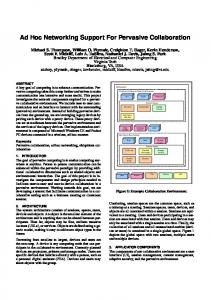
Fig. 1 Representative sketch of the autonomous spacecraft assembly test bed.
331
BEVILACQUA ET AL.
III.
Hardware Selection and Description
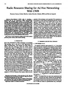
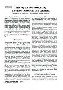
Figure 1 depicts the test bed at the SRL. Main components and their interfaces are illustrated onboard the robot at the bottom of the sketch. The configuration and the software architecture presented here is in principle scalable to an arbitrary number of robots. Figure 2 presents the three robots currently operational in the Spacecraft Robotics Laboratory at the Naval Postgraduate School. Figure 3 depicts the main hardware components with respect to data exchange command and data handling subsystem on each of four spacecraft simulators at the SRL. Arrows are used to illustrate how the different components are assembled and connected to each other. Table 1 lists the hardware components by name and part number, the manufacturer and a description of the key characteristics. To set up a wireless ad hoc network it is necessary to determine a properly supported device with respect to the necessary drivers and firmware packages for the given OS. Ref. [37] provides an exhaustive list of wireless adapters (USB, PCI cards, etc.. . .) with the indication of their compatibility with Linux. In the initial stages of this research effort, an extensive trade study was performed using Ref. [37] as a primary reference to determine a wireless adaptor that would be hardware and software compatible with an RTAI Linux-based PC/104 real-time computing solution. The outcome of this study first drove the component selection to a USB wireless adapter owing in most part to its space and power saving qualities, ease of installation and removal, and its direct compatibility with any PC/104 motherboard with at least one USB port. Unfortunately, during full-scale real-time experimental testing, it was discovered that RTAI does not properly handle USB interrupts, requiring a USB device to exit out of the real-time computing process, execute any required USB instructions, and then reenter the real-time process. This strong limitation resulted in an extended search for other wireless adapter alternatives and revolved around the possibility of converting a standard RJ-45 10Base-T Ethernet port to a wireless radio signal. The D-Link Pocket
Fig. 2 Three spacecraft simulators, part of the autonomous spacecraft assembly test bed at the NPS Spacecraft Robotics Laboratory.
332
BEVILACQUA ET AL.
Fig. 3 Critical components of each spacecraft simulator.
Wireless meets this requirement with a 5 Volt power requirement and allows the user to mode select among router, access point or ad hoc client. The wireless ad hoc network not only provides for inter-robot communication and experimental data logging on a host desktop computer, it also enables the user remotely to log into the onboard PC/104s from this host computer and make modifications to the system, load executable files, and run and stop execution of real-time tasks. As the host computer does not have real-time computing requirements, it can use the USB wireless adapter selected in the original trade study to communicate with the network. The steps to install and setup the wireless ad hoc network under Linux are provided in the Appendix. The wireless ad hoc network capability of each robot is not only used to communicate with other robots. It is also necessary to receive its own absolute position in the laboratory as sensed by the Metris® iGPS indoor positioning system. The iGPS system is a commercial system that requires a Windows-based computer to process and convert the raw data, streaming from the receiver via RS232 serial interface, into position measurements. Therefore, a wireless 333
BEVILACQUA ET AL.
Table 1 Hardware description Component name (part No.)
Manufacturer
PC/104+ motherboard
Advanced Digital Logic
Extreme IV compact flash card 20 relay board (IR-104-PBF) 8 serial port board (MSMX104+) Firewire PC/104 board Compact wireless-G USB adapter Wireless pocket router/AP (DWL-G730AP) Solenoid valves Fiber optic gyro (DSP-3000) Magnetometer (MicroMag-3Axis) DC/DC converters (EK-05 battery controller and regulator +DC1U-1VR 24V DC/DC converter) Battery iGPS indoor positioning system
Inspired Energy Metris
Description
SmartCoreT3-400, 400 Mhz central processing unit (CPU) SDRAM256-PS SanDisk 8 Gbyte capacity Diamond Systems High Density Opto-isolated I/O Board Advanced Digital Logic – Embedded Designs Plus IEEE1394 Card with 16 Bit PC104 Linksys 54Mbps 802.11b/g D-Link 2.4 Ghz 802.11 g, RJ-45 to wireless Predyne 2 way, 24 VDC, 2 Watt KVH 100 Hz, Asynchronous, RS-232 PNI Asynchronous, RS-232 Ocean Server 3.3, 5, 12, 24 Volts outputs. Main board is equipped with a batteries status controller. Lithium Ion rechargeable battery −95 Whr Capable of < 0.005 m precision
server is installed next to the onboard receiver to convert the serial signal to wireless TCP/IP. An external Windowsbased computer running the propriety software program receives these raw data through a standard wireless PCI adapter, processes the data and then sends the Cartesian coordinates over the wireless ad hoc network in UDP format to the simulators. The UDP data are packed using a Python program. This is the only connection to a Windows computer and the only off-board processing that is done on the test bed with the data logging and telecommanding being performed over the wireless ad hoc network on a Linux-based desktop computer. RTAI Linux is installed on each robot’s PC/104 via 8 Gbyte compact flash (CF) cards. The steps to move the OS from the desktop computer and make it bootable on the CF are detailed in the Appendix. The procedures can be quickly duplicated enabling a generic number of N robots to be equipped with the same OS. The main advantages of using CFs over traditional hard disk drives are: reduced size, low power consumption, no moving parts, very good read/write performance, and extreme portability. With the focus of this paper being on the software and wireless ad hoc infrastructure, additional clarification and qualification of the hardware choices listed in Table 1 can be found in Ref [38].
IV.
Real-Time Software for Sensors and Actuators
Figure 4 shows the Simulink! library developed to communicate with the hardware. Figure 4 reports the individual blocks’ masks allowing the user to set up the main parameters for each hardware device. Each of the developed Simulink! blocks uses an S-function construct to integrate C code into the models. The Appendix collects some notes for the users. One important issue that arose while using Simulink! is the fact that the clock and ramp generator blocks do not work once compiled and executed under RTAI Linux and can cause the onboard PC/104 to freeze or crash. This is related to the task execution hierarchy which causes the system to exit the real-time RTAI layer to accomplish the requisite tasking and then returning. To alleviate this problem, we developed a new clock generation block which provides real-time clocking without interfering in the real-time computational process. The following explains the main inputs to the S-function blocks’ masks in Fig. 5 and the input/output (I/O) signals for the blocks in Fig. 4. For the three blocks using COM ports (RS232), i.e. the ones in Fig. 5 a, b and i, the same parameters encountered in xPC Target™ RS232 blocks are required. Throughout the discussion that follows, the bold terms are the names of the parameters, block’s inputs/outputs and block’s names: LIST OF INPUTS AND OUTPUTS (from Fig. 4) a. KVH DSP-3000 Fiber Optic Gyro: RS232 source block. It provides the angular rate (rate) and a flag. The flag is either 0 (bad data or no available data) or 1 (good data). The flag indicates whether the message’s parsing has been successful or not. 334
BEVILACQUA ET AL.
Fig. 4 Simulink! Library developed for Linux.
b.
c. d.
PNI Micro-Mag 3-Axis Magnetometer: RS232 source block. It provides an angle (angle) and a flag. The flag is either 0 (bad data or no available data) or 1 (good data). The flag indicates whether the message’s parsing has been successful or not. Despite the capability of this device to provide three angles we are parsing out only one angle, setting the magnetometer in a single axis configuration. This is for simplicity and because one angle is what the SRL robots need to measure. Metris iGPS Position Measurement: UDP source block. It provides planar position coordinates (Y, X) in meters and a flag. The flag is either 0 (bad data or no available data) or 1 (good data). Diamond IR-104-PBF Relay Board: Output bit sink block. The input varies dynamically with the number of channels the user desires to activate (Fig. 5d, only channel 1 is activated in the figure). 1 at input means relay on (circuit is closed, allows power to go through), 0 means off (opens circuit, no power through). 335
BEVILACQUA ET AL.
e. f. g.
Linux Unpack: Data type conversion I/O block. The packed UDP binary data are the input while the unpacked data are the output, after the data have been unpacked according to the definitions in the mask. Linux UDP Send Binary: UDP sink block. The input is the packed value sent as a UDP signal. Linux Pack: Data type conversion I/O block. The unpacked data are the input while the packed UDP binary signal is the output after the data have been packed according to the definitions in the mask.
Fig. 5 Simulink! Masks with respective input parameters for the blocks of Fig. 4.
336
BEVILACQUA ET AL.
Fig. 5 Simulink! Masks with respective input parameters for the blocks of Fig. 4 (Continued).
h. i.
Linux UDP Receive Binary: UDP source block. The input is the packed value coming as a UDP signal. Flag is either 1 or 0 according to the case of receiving or not receiving data. Ocean Server Batteries Controller: RS232 source block. It provides an average percent charge of the batteries connected to the DC/DC converters (charge %) and a flag. The flag is either 0 (bad data or no available data) or 1 (good data). The flag indicates whether the message’s parsing has been successful or not. 337
BEVILACQUA ET AL.
Clock: Source block that outputs the current time from the beginning of the task’s execution. Linux Firewire Frame Grabber: Firewire-based source block. It outputs the captured image (Image) as a collection of bytes which represent the light intensity of the pixels. It also outputs the size of the image in bytes. l. Linux Image Processor: Data type conversion I/O block. Image is the output image of the capture block while x and y are the normalized coordinates of the brightest three points in the image. The ranges of x and y between -1 and 1, being (0, 0) the center of the image. Flag is zero if no new measurement is available, 1 is a new one is computed. LIST OF PARAMETERS (from Fig. 5) a. KVH DSP-3000 Fiber Optic Gyro: Port: Serial port number. Baud rate: Baud rate of the specific device connected to Port (from device manual). Number of data bits: Number of data bits in message from device (from device manual). Number of stop bits: Number of stop bits in message from device (from device manual). Parity: Parity check on message from device (from device manual). Sample Time: Sampling time interval for reading/writing to the Port. b. PNI Micro-Mag 3-Axis Magnetometer: Port: Serial port number. Baud rate: Baud rate of the specific device connected to Port (from device manual). Number of data bits: Number of data bits in message from device (from device manual). Number of stop bits: Number of stop bits in message from device (from device manual). Parity: Parity check on message from device (from device manual). Sample Time: Sampling time interval for reading/writing to the Port. c. Metris iGPS Position Measurement: IP address of your PC: IP address of the computer receiving data. It is needed to bind a UDP port. The iGPS program, being specific for receiving two doubles (the two coordinates in the laboratory), does not allow changing this value. Sample Time: Sampling time interval for checking new data availability at the UDP port. d. Diamond IR-104-PBF Relay Board: Channel Vector: Relays to be commanded (from 1 to 20, they do not have to be consecutive). Reset Vector: Status at which the relays are left when the execution is terminated. Initial Value Vector: Initial status of the relays at beginning of execution. Sample Time: Sampling time interval at which the relays are commanded. Base address: base hardware address of the relay board. e. Linux Unpack: Output port dimensions: Number of elements to unpack the incoming message into. Output port data types: Data types of the elements to unpack the incoming message into. f. Linux UDP Send Binary: IP port address to send to: IP address of the remote computer receiving UDP data. Remote IP port to send to: IP port to which the remote computer will bind. Then, it has to be equal to the value of the receiving party (Fig. 5h). Sample Time: Sampling time interval for sending data through the UDP port. g. Linux Pack: Input port data types: Data types of the elements to be packed in a single message. h. Linux UDP Receive Binary: IP port to receive from: IP port to bind. This value has to be the same as the sending party. Output port width (number of bytes): The receive UDP needs to know how many bytes are contained in each packet. Sample Time: Sampling time interval for checking new data availability at the UDP port. i. Ocean Server Batteries Controller: Port: Serial port number. Baud rate: Baud rate of the specific device connected to Port (from device manual). Number of data bits: Number of data bits in message from device (from device manual). Number of stop bits: Number of stop bits in message from device (from device manual). Parity: Parity check on message from device (from device manual). Sample Time: Sampling time interval for reading/writing to the Port. j. Clock: Sample Time: It must be the main model sampling time (the one set up under configurations of the Simulink! model). k. Linux Firewire Frame Grabber: Output Port Width: Number of bytes required for the image to be grabbed. Sample Time: Sampling time for requiring a new image from the camera. This block may need to be scheduled at a lower frequency than the main control system, accordingly with the CPU computing capabilities, to avoid overload and lose of real-time execution of the guidance, navigation, and control (GNC) algorithms. j. k.
338
BEVILACQUA ET AL.
l.
Linux Image Processor: This block does not require a mask. This block may need to be scheduled at a lower frequency than the main control system, accordingly with the CPU computing capabilities, to avoid overload and lose of real-time execution of the GNC algorithms.
V.
Experimental Results
This section presents the results of three real-time experimental test runs. In all of the tests, four PC/104 computers are running in real-time using RTAI Linux, exchanging data over the established Wi-Fi ad hoc network to control one fully operational autonomous robot. Only one of the four computers is physically mounted on board the robot (see Fig. 6). The executable files are obtained from Simulink! models implemented using the library described in the
Fig. 6 Representative sketch of the real-time test data exchanging and distributed computing.
339
BEVILACQUA ET AL.
previous section. The details of the GN&C algorithms are beyond the scope of this work and will not be discussed here. For further details on the GN&C algorithms refer to [10] and [11]. A video capture of the experimental tests is available (videos\DistributedSquare.MOV for test 1, videos\DistributedInterruptedValvesOff.MOV for test 2 and videos\DistributedInterruptedValveOn.MOV for test 3). The first test shows the real-time distributed computing capability over the ad hoc Wi-Fi network. A sample closed trajectory maneuver is completed in test 1. Test 2 and test 3 present the same experiment with an interruption of the wireless communication between the PC/104 performing the thruster mapping and the maneuvering robot to explicitly demonstrate the loss of control on the robot and further prove the interdependency of the computers over the Wi-Fi link during distributed computing. A. Test 1 The main goals of the first test are to prove RTAI Linux’s real-time capability for the developed system (negligible latency) and the negligibility of the delays in communication with the Wi-Fi ad hoc network during distributed computing. Refer to the video videos\DistributedSquare.MOV for the test visualization. Figure 6 describes the data exchanging among the PC/104s and the real-time tasks each of them is executing for the presented test. The tasks running onboard each computer are sampled at 100 Hz (sample time is 0.01 s). During the experiment, the robot maneuvers to follow a one meter side square while maintaining zero attitude and angular velocity throughout. Also, the velocity along each side of the square is commanded to be one centimeter per second and at rest at the corners. Each PC/104 executes the compiled version of a Simulink! model and each of the models interfaces to the others (see Fig. 6) via Wi-Fi UDP. Furthermore, each PC/104 sends back to the desktop PC its sensitive data so that the whole execution can be monitored and the telemetry stored. The robot’s onboard time is broadcast to the navigation, control and thruster mapping tasks, so that these last three tasks actually start computing data only when the robot
Fig. 7 Trajectory followed by the operational robot during distributed computing. The position is sensed via the iGPS indoor system on the robot (IP 170.160.1.4) and collected wirelessly on the desktop PC (IP 170.160.1.7).
340
BEVILACQUA ET AL.
Fig. 8 Controls commanded to the solenoid valves. The commands are computed by the thruster mapping software on PC104 with IP 170.160.1.3 and received by the robot (IP 170.160.1.4). The commands are also collected wirelessly on the desktop PC (IP 170.160.1.7).
341
BEVILACQUA ET AL.
requires them, i.e. only when it starts broadcasting time and sensor data. Figure 7 presents both the commanded trajectory and the logged trajectory from the robot. Figure 8 shows the on/off thruster commands sent to the robot by the thruster mapping PC/104. The results of the presented test demonstrate the correct functioning of the developed real-time Simulink! blocks that interact with the onboard sensors and actuators. Furthermore, the four intercommunication pathways required to command the actuators on the robot, starting from the current sensed position and attitude, occur in less than 0.01 seconds. This is demonstrated by the performed maneuver, whose accuracy is satisfactory. In other words the wireless network’s delays are negligible as also is the data loss in Wi-Fi communication. B. Test 2 This test presents the same characteristics of Test 1. To show the PC/104 interdependency while performing distributed computing, the wireless connection between the commanding PC/104 (IP 170.160.1.3) and the maneuvering robot (IP 170.160.1.4) is manually interrupted by disconnecting the Ethernet cable (videos\DistributedInterruptedValvesOff.MOV). In particular, the communication loss implies no control on the robot because it no longer receives any commands for the solenoid valves. The disconnection occurs when all the valves are off in this test and thus the simulator drifts away uncontrolled. C. Test 3 This test presents the same characteristics of Test 1. Once more, to show the PC/104 interdependency while performing distributed computing, the wireless connection between the commanding PC/104 (IP 170.160.1.3) and the maneuvering robot (IP 170.160.1.4) is manually interrupted by disconnecting the Ethernet cable (videos\DistributedInterruptedValveOn.MOV). However, in this test, the disconnection occurs when one valve is still on causing the robot to enter an uncontrolled spin.
VI.
Conclusion
This paper presents the implementation details of a wireless ad hoc communication network and the software infrastructure for real-time maneuvering of multiple robotic systems. The approach presented is applicable in general to any multi-robot system. Key aspects of this generality include the use of a wireless communication network based on the IEEE 802.11 standard and the exportability and customizability of the Simulink! C-code-based S-functions. RTAI Linux is chosen as the real-time OS with its advantage of being able quickly to use Simulink! models using Real-Time Workshop™ for automatic generation of the real-time executable files. A Simulink! library has been developed as interface between software and hardware. In particular, the developed software has been applied to the spacecraft simulators of the Autonomous Spacecraft Assembly Test Bed at the Spacecraft Robotics Laboratory of the Naval Postgraduate School. To prove the real-time capability of the developed software infrastructure, i.e. the dedicated libraries for the hardware and the wireless networking in real-time, three experimental tests are presented. In the first test, realtime distributed computing over the Wi-Fi network is demonstrated by controlling one maneuvering robot through a parceled out framework of different wirelessly connected PC/104s running the navigation, control, and thruster mapping algorithms. The real-time OS latencies and the wireless communication delays and data loss result to be negligible even with four simultaneous Wi-Fi data exchange being required within a sample time of 0.01. The second and third tests reproduce the first one with the addition of the manual disconnection of the wireless link between the commanding PC/104 and the maneuvering robot to demonstrate the effect of control loss on the maneuvering robot and distributed computing interdependency. The configuration and the software architecture presented here is in principle scalable to an arbitrary number of robots. The material in the included Appendix is suitable to build ready-to-use systems for multiple robot applications. Furthermore, the Simulink library is available upon request from the authors.
VII.
Appendix
The following is the procedure followed for the preparation of the real-time OS: RTAI Linux. It applies to a desktop PC. The system copying on smaller drives and in particular to the compact flashes is given as well. The 342
BEVILACQUA ET AL.
installation of Matlab and the whole process to generate C code from a Simulink model is described. The steps for using Real-Time-Workshop, and finally obtaining an executable file to run under RTAI are reported. The remote wireless connection from the desktop to the PC104 to upload executable files and run them is illustrated. Despite the strong limitations of the xrtailab GUI, the installation and test process for it is also included. The Simulink library is publicly available for research purposes upon request from the authors. The Debian 2.6.19 kernel release is chosen, owing to its streamlined and basic nature. However, because it is so streamlined, some required packages such as a C compiler and other specific ones required by RTAI must be added. For this reason, those who choose to explicitly follow the installation instructions outlined in the Appendix will find several additional packages downloaded after the initial Debian installation. In setting up the RTAI patch, we initially referred to the manuals of [36] and [39] with particular emphasis on the generic instructions pertaining to the required software packages (Mesa, Comedi, Comedilib, etc.). In beginning the installation, the first step is to download a stable release of Debian (kernel 2.6.18) from which it is possible to access, download and compile the remaining packages, and finally the 2.6.19 kernel which is ultimately patched with RTAI. During the first installation and for any testing of the system to include debugging errors, etc., it is extremely more expeditious to use high end desktop computer vice the onboard PC/104 single board computers. Once the OS is fully prepared for the selected PC/104 processor, it is sufficient to simply duplicate it to a removable drive such as a compact flash that can be later connected to the onboard PC/104. This final step of duplication can also be performed on the desktop computer given the requisite card reader. The use of a fast desktop computer for compilation cannot be stressed enough as in most circumstances it can help decrease the time to compile by an order of magnitude. Some attention to computer architecture, especially the microprocessor, is important during this process As the Linux kernel and software tools can be compiled to a specific architecture and thus be potentially un-executable on a different computer. A. Installation on desktop PC 1) Start Linux Installation by CD install of Debian (e.g. http://www.debian.org/CD/netinst/). 2) Be super user (root) for all the following steps, unless otherwise specified. 3) Install required packages: (to avoid being asked to use the Debian disk go to Desktop, Administration, Software Properties and remove the cdrom as source for packages) >> apt-get install gcc-3.4 >> ln –s /usr/bin/gcc-3.4 /usr/bin/gcc >> ln –s /usr/bin/gcc-3.4 /usr/bin/g++ >> apt-get install build-essential >> apt-get install libncurses-dev >> apt-get install x11proto-xext-dev >> apt-get install automake >> apt-get install autoconf >> apt-get install libtool >> apt-get install bison >> apt-get install doxygen >> apt-get install initrd-tools >> apt-get install libxmu-dev >> apt-get install libjpeg-dev >> apt-get install libgtk2.0-dev >> apt-get install xlibmesa-gl >> apt-get install xlibmesa-glu >> apt-get install xlibmesa-glu-dev >> apt-get install xlibmesa-dri >> apt-get install mesa-utils >> apt-get install libgl1-mesa-swrast-dev >> apt-get install ssh 343
BEVILACQUA ET AL.
4)
5)
6)
7)
8)
Install Mesa >> cd /usr/local/src Visit http://www.mesa3d.org and download MesaLib-6.5.3.tar.bz2 >> bunzip2 /home/(user name)/Desktop/Downloads/MesaLib-6.5.3.tar.bz2 >> cp/home/(user name)/Desktop/Downloads/MesaLib-6.5.3.tar. >> tar –xvf MesaLib-6.5.3.tar >> cd Mesa-6.5.3 >> make realclean >> make linux-x86 >> make install Install EFLTK >> cd /usr/local/src >> apt-get install subversion >> apt-get install gettext >> apt-get install flex >> svn co https://ede.svn.sourceforge.net/svnroot/ede/trunk/efltk >> cd efltk >> autoconf >> ./configure –disable-mysql –disable-unixODBC >> ./emake >> ./emake install >> pico –w /etc/ld.so.conf Add /usr/local/lib and then save the file (CNTL-X, Y to save question) >> /sbin/ldconfig >> cp efltk-config bin/ Install Comedilib >> cd /usr/local/src Visit http://www.comedi.org/download/ and download comedilib-0.8.1.tar.gz >> gunzip /home/(user name)/Desktop/Downloads/comedilib-0.8.1.tar.gz >> cp/home/(user name)/Desktop/Downloads/comedilib-0.8.1.tar. >> tar–xvf comedilib-0.8.1.tar >> cd comedilib-0.8.1 >> sh autogen.sh >> ./configure –sysconfdir=/etc/ >> make >> make install >> make dev Download Debian kernel 2.6.19 Visit http://www.kernel.org/pub/linux/kernel/v2.6 and download linux-2.6.19.tar.gz >> cd /usr/src >> gunzip /home/(user name)/Desktop/Downloads/linux-2.6.19.tar.gz >> cp /home/(user name)/Desktop/Downloads/linux-2.6.19.tar. >> tar –xvf linux-2.6.19.tar >> mv linux-2.6.19 linux-2.6.19-rtai >> ln –s linux-2.6.19-rtai linux Install RTAI >> cd /usr/src Visit https://www.rtai.org/RTAI/ and download rtai−3.5.tar.bz2 >> bunzip2 /home/(user name)/Desktop/Downloads/rtai-3.5.tar.bz2 >> cp /home/(user name)/Desktop/Downloads/rtai-3.5.tar. 344
BEVILACQUA ET AL.
9)
10)
>> tar –xvf rtai-3.5.tar >> ln –s rtai-3.5 rtai Patching the kernel and compiling >> cd /usr/src/linux >> patch –p1 < /usr/src/rtai/base/arch/i386/patches/hal (TAB to match version to 2.6.19) >> cp /boot/config-2.6.18-5-686 .config >> make oldconfig (Answer default option for each question) >> make menuconfig -Code maturity level options: select “Prompt for development. . .” -General Setup: “Local Version”. . ., enter -rtai -Loadable Module Support: select “Enable Module Support”, “Module unloading” and “Automatic Module Loading”. Unselect “Module versioning support”. -Processor Type and Features: deselect “Symmetric multi-processing support”, “subarchitecture” has to be PC compatible. Select “Processor Family” according to PC. Select “Preemption Model” and select preemptible kernel (low latency desktop). Unselect “Local APIC support on uni processors” and have “High memory Support” (4 Gb). Unselect “Use Register Arguments”. -Power Management: totally unselected. ACPI, APM and CPU unselected. -Device Drivers: unselect “Memory Technology Device”, “Parallel Port Support”, “Multiple Devices Driver Support”, “ISDN support”, “Telephony support”. “Input device support” has to have mouse selected. In “Character Devices” select /dev/agpart/ AGP support and Direct Rendering Manager. . . . Being still in Character Devices go under “serial drivers” (THIS STEP IS NEEDED TO USE THE PC104 8 PORTS SERIAL BOARD). Select 8250/16550 and compatible serial support. Maximum number of 8252/16550 serial ports →16. Number of 8250/16550 serial ports to register at run time →16. Select Extended 8250/16550 serial driver options and support for sharing serial interrupts. Back into Device Drivers unselect “I2C support”, “Multimedia devices”, “Graphics Support”. Sound and USB support enabled as modules. -File Systems: select Ext3. >> make >> make modules_install >> make install >> pico –w /boot/grub/menu.lst Change default to 2 (beginning of file). Insert, right before END DEBIAN AUTOMAGIC KERNELS LIST (bottom of file) the following: title Debian GNU/Linux, kernel 2.6.19-rtai root (hd0,0) kernel /boot/vmlinuz-2.6.19-rtai root=/dev/hda1 irqpoll ro initrd /boot/initrd-2.6.19-rtai savedefault title Debian GNU/Linux, kernel 2.6.19-rtai (single-user mode) root (hd0,0) kernel /boot/vmlinuz-2.6.19-rtai root=/dev/hda1 ro single initrd /boot/initrd.img-2.6.19-rtai savedefault (NOTE: the irqpoll instruction is needed to access the 8 serial ports PC104 board) >> mkinitrd –o /boot/initrd-2.6.19-rtai 2.6.19-rtai >> reboot RTAI 1st Pass >> cd /usr/src/rtai >> make menuconfig Menu General: Verify default directories: ∗ installation directory /usr/realtime 345
BEVILACQUA ET AL.
∗
11)
12)
13)
Kernel source directory /usr/src/linux Menu General: optionally select RTAI documentation Menu Machine (x86): adjust number of CPUs to 1 >> make >> make install >> pico –w /etc/profile Add “:/usr/realtime/bin” to both PATH=lines Install Comedi >> cd /usr/local/src Visit http://www.comedi.org/download/ and download comedi-0.7.75.tar.gz >> gunzip /home/(user name)/Desktop/Downloads/comedi0.7.75.tar.gz >> cp/home/(user name)/Desktop/Downloads/comedi-0.7.75.tar. >> tar –xvf comedi-0.7.75.tar >> cd comedi-0.7.75 >> sh autogen.sh >> ./configure –with-linuxdir=/usr/src/linux –with-rtaidir=/usr/realtime >> make >> make install >> depmod -a >> make dev >> cp include/linux/comedi.h include/linux/comedilib.h /usr/include/ >> cp include/linux/comedi.h include/linux/comedilib.h /usr/local/include/ >> ln –s /usr/include/comedi.h /usr/include/linux/comedi.h >> ln –s /usr/include/comedilib.h /usr/include/linux/comedilib.h >> cd /usr/src/rtai >> make menuconfig Menu Add-Ons: Select Comedi support over LXRT and change path to be “/usr/local/src/comedi-0.7.75” Menu RTAI Lab: Select RTAI Lab and change path to be “/usr/local/src/efltk” >> make >> make install >> make dev >> insmod /usr/realtime/modules/rtai_hal.ko >> insmod /usr/realtime/modules/rtai_up.ko >> insmod /usr/realtime/modules/rtai_fifos.ko RTAI tests >> cd /usr/realtime/testsuite/kern/latency >> ./run >> cd ../preempt >> ./run >> cd ../switches >> ./run If good results CNTRL-C. If they do not work do >> make dev under >> cd /usr/src/rtai and then try again. Modifying startup file >> pico –w /etc/rc2.d/S99rc.local At end of file, add: sync insmod/usr/realtime/modules/rtai_hal.ko insmod/usr/realtime/modules/rtai_up.ko insmod/usr/realtime/modules/rtai_fifos.ko insmod/usr/realtime/modules/rtai_sem.ko 346
BEVILACQUA ET AL.
14) 15)
16)
insmod/usr/realtime/modules/rtai_mbx.ko insmod/usr/realtime/modules/rtai_msg.ko insmod/usr/realtime/modules/rtai_netrpc.ko ThisNode=”127.0.0.1” sync >>cd /usr/src/rtai >>make dev >> reboot Retry three RTAI tests and also type >> /usr/realtime/bin/xrtailab &, to see if the GUI pops up If they don’t work do >> make dev under >> cd /usr/src/rtai and then try again. Install and setting up Matlab >> apt-get install x-window-system >> mount /dev/(name of device: cdrom, etc. . . .)/ /mnt/ >> cd /usr/local/ >> mkdir matlab >> cd matlab >> pico –w license.dat Paste Linux license file and save file >> /mnt/install OK to all default options. While installing, modify startup file as: >> pico –w /etc/rc2.d/S99rc.local, add, at the end of the file: cd /usr/local/matlab/etc ./lmstart –u (user name) >>umount /mnt (eject cd/dvd) After completed install, >> reboot Verify install >> cd /usr/local/matlab/bin >> ./matlab & (Matlab should open up; close it) >> cd .. >> mkdir rtw/c/rtai >> cp –r/usr/src/rtai/rtai-lab/matlab/* /usr/local/matlab/rtw/c/rtai >> cd/usr/local/matlab/bin >> ./matlab & in Matlab prompt go to/usr/local/matlab/rtw/c/rtai -launch setup in Matlab window -cd devices/ (just double click on the devices folder on the left list of Matlab) -mex all files .c in the folder (e.g. mex sfun_comedi_data_read.c) -cd .. (just go up in the Matlab list on the left) -double click on rtai.tmf (this is needed to generate a code which can be compiled for rtai later) -do a search on ANSI. Delete $(ANSI_OPTS) when found (there is only one) -do a search on RTAIDIR. Delete everything after=and replace with /usr/realtime -go to/usr/local/matlab/bin (still in Matlab). -double click on mexopts.sh (this is needed for generating code from S-function blocks in Simulink models) -do a search on ANSI and delete -ansi when found (four different places) First test on generating code from Simulink, compile it and execute it under RTAI in real-time still with Matlab open go to /usr/local/matlab/rtw/c/rtai/examples copy the test.mdl Go to /usr/local/src create new folder named tests 347
BEVILACQUA ET AL.
17)
18)
paste the test.mdl in this folder open test.mdl Real-Time-Workshop: go to Simulation-Configuration Parameters in the scrolling down menu: select rtai.tlc as target, generate code only, click generate go back to root terminal >> cd/usr/local/src/tests/test_rtai >> make –ftest.mk (generates executable) >> cd .. >> ./test –v –f 5 (runs for 5 seconds) NOTE for compiling code: if the make –f nameofthemodel.mk complains that it does not find nameofthemodel.o file copy the nameofthemodel.c file where you are launching the make –f nameofthemodel.mk, or, in Matlab, remember to include the folder containing nameofthemodel.c file in Matlab path before generating code from Real-Time-Workshop. Ad Hoc Wireless infrastructure installation (for desktop: USB wireless adapter) >>apt-get install wireless-tools Visit http://web.ralinktech.com/ralink/Home/Support/Linux.html and download 2008_0117_RT73_Linux_ STA_Drv1.1.0.0.tar.bz2 >> cd /usr/local/src >> bunzip2 /home/(user name)/Desktop/Downloads/2008_0117_RT73_Linux_STA_Drv1.1.0.0.tar.bz2 >> cp /home/(user name)/Desktop/Downloads/2008_0117_RT73_Linux_STA_Drv1.1.0.0.tar. >> tar –xvf 2008_0117_RT73_Linux_STA_Drv1.1.0.0.tar >> cd 2008_0117_RT73_Linux_STA_Drv1.1.0.0/Module >> cp Makefile.6 ./Makefile >> chmod 755 Configure >> make config >> pico –w rtmp_main.c CNTRL-W search for get_wireless_stats Comment out (//) line: netdev->get_wireless_stats=rt73_get_wireless_stats; CNTRL-W search again for get_wireless_stats Comment out (//) line: netdev->get_wireless_stats=rt73_get_wireless_stats; save the file with modifications >> make all >> mkdir /etc/Wireless >> mkdir/etc/Wireless/RT73STA >> cp rt73.bin/etc/Wireless/RT73STA >> apt-get install tofrodos >> dos2unix rt73sta.dat >> cp rt73sta.dat /etc/Wireless/RT73STA/rt73sta.dat >> pico –w /etc/Wireless/RT73STA/rt73sta.dat Change lines SSID=SRL2 (or appropriate name: name of the wireless network) NetworkType=Adhoc Channel = 11 Setting up startup file to load the wireless ad hoc network automatically at boot up >> pico –w /etc/init.d/wireless_script Add the following lines, but change net address as desired (first three numbers will represent the ad hoc network) /sbin/insmod/usr/local/src/2008_0117_RT73_Linux_STA_Drv1.1.0.0/Module/rt73.ko /sbin/ifconfig rausb0 up 348
BEVILACQUA ET AL.
19)
/sbin/ifconfig rausb0 inet 170.160.1.1(chose a convenient IP) up >> chmod 777 /etc/init.d/wireless_script >> cd/etc/rc2.d >> ln –s/etc/init.d/wireless_script S99Wireless >> cd /etc/rc5.d >> ln –s/etc/init.d/wireless_script S99Wireless reboot and check the ad hoc installation through ifconfig and iwconfig Ad Hoc Wireless infrastructure installation (for PC104: wireless pocket) Connect the D-Link device to the Ethernet port. Set client on the bottom switch of the device. Follow the device manual to access it via a browser. Choose ad hoc and an IP in the same family of the robots’ ones. At this point the Ethernet port of the PC104 must be set up as static IP and the IP has to be the one we want to assign to the robot: >>pico –w /etc/network/interfaces change dhcp to static add the lines: address (chosen IP) netmask 255.255.255.0
B. Firewire camera 1) Download libdc1394-1.1.0 and libraw1394-1.2.0 from sourceforge website. Unzip and untar under /usr/local/src. 2) In both libraries type: >> ./configure >>make >>make install (libdc fails on some points, ignore them) 3) 4)
5)
Copy libdc1394-control.so.13 from its location to /lib (find it by typing >>find –name “libdc1394control.so.13” -print). To be able to mex S-functions using the firewire libraries: open Matlab and go to /usr/local/matlab/bin. Double click on mexopts.sh (this is needed for generating code from S-function blocks in Simulink models) and add to line 52 (CLIBS-$ . . .) the following: - ldc1394-control - lraw1394 - pthread (needed for the S-function developed for capturing images) - lsupc ++ (to be able to compile C++ code) still in Matlab prompt go to /usr/local/matlab/rtw/c/rtai, double click on rtai.tmf and add to line 74 (SYSLIB) the following: - ldc1394-control - lraw1394 - pthread (needed for the S-function developed for capturing images) - lsupc ++ (to be able to compile C++ code)
C. Copying System on CF and make it bootable for PC104 After having connected the CF to the desktop PC hosting the complete RTAI Linux system it needs the following steps: 1) Formatting CF and creating file system >> fdisk /dev/hdc (hdc could be something different, it needs to match the device under which the CF is shown. To check the name of the devices type fdisk –l /dev/h(or s, . . .)d. . . (a, b, c), to recognize them.) >>d (delete previous partitions) >>n (new partition) >>p (create partition) >>1 (this is the Linux partition, leave at least 2 Gb for the swap partition) >>t (type of partition) >>83 (Linux partition) >>a (choose bootable partition) 349
BEVILACQUA ET AL.
2)
3) 4)
5)
>>1 >>n (adding swap partition) >>p >>2 >>t >>2 >>82 (swap partition) >>w (writes changes and exits) >>mkfs.ext3 /dev/hdc1 (hdc could be something different, it needs to match the device under which the CF is shown, see previous note) >>mkswap /dev/hdc2 Copy system to the CF and make it bootable >>mount /dev/hdc1 mnt/ >> cd / (go to root in the desktop PC file system) >>cp –av * mnt/ (* indicates any folder under the root of the desktop PC. Copy them one by one EXCEPT for cdrom, media, proc, mnt ) >>mkdir /mnt/proc >>cd mnt/ >> pico –w boot/grub/device.map change hda or what it appears to the correct name for the device (hdc in our case). Save and exit. >>pico –w boot/grub/menu.lst change hda or what it appears to the correct name for the device (hdc in our case). Save and exit. >>grub-install –root-directory=/mnt/ /dev/hdc (hdc could be something different, it needs to match the device under which the CF is shown) Boot kernel 2.6.18 from CF still connected on desktop PC. Recompile kernel 2.6.19 for new processor (see steps in previous Section A of the Appendix, point 8. Just run make menuconfig and change type of processor) >>pico –w /etc/fstab and modify the swap row to be /dev/hdc2 NOTE: once the system is ready, the IP can be changed by simply accessing the wireless_script file (Section A of the Appendix, point 18). Move to the PC104 and boot up. Test RTAI (Section A of the Appendix, point 1812), it may need a recompilation or a make dev under /usr/src/rtai (Section A of the Appendix, point 1018).
D. Connect to the PC104 from the desktop to upload executable files 1) Access a NON ROOT terminal (not super user) on the desktop PC. >>cd /usr/local/src/tests (we are assuming the executable is under this folder) >>sftp (user name of PC104…which should be the same of desktop, having copied the system)@IP PC104 >>put (name executable) (this command will copy the executable in the /home/user name folder of the PC104) >>exit >>ssh (user name of PC104)@IP PC104 Now it is possible to become super user, we are logged into the PC104, it can be commanded from the desktop: copying files, move them, execute real-time tasks, etc. . . .NOTE: we have noticed that sometimes the real-time task remains hanging on the computer stack of processes if has not been called with the proper options. This leads the system to not being able to re-run a process after it has been stopped. If this occurs (the ps command, entered at the system prompt, lists the processes going on). 2) A faster way to maintain a continuous connection via ssh to the PC104, without opening a new one with sftp to copy the files, is by: >> cd /usr/local/src/tests (we are assuming the executable is under this folder) >>scp (name executable) user_name_on_PC104@IP:/(path where to copy the executable on PC104) 350
BEVILACQUA ET AL.
E. C S-functions notes for users The following is the list of the C functions and C S-functions developed for the Simulink library under RTAI. Each function needs to be mexed via the “mex” command in Matlab before the corresponding Simulink block is available to use it. Once all functions are ready, it may be convenient to keep them and the mexed versions into a Linux Include folder which needs to be in the Matlab list of paths so that the Simulink blocks can use them. • rs232com.c: sets up the serial port number, baud rate, bit parity and so on. It is a generic C function which is called by the specific C S-functions which interact with the different serial devices. It is run once for each serial port, before the C S-functions start sending and receiving data via the RS-232 ports. • dsp3000a.c: this is a C S-function, it sends a command to the Fiber Optic Gyro which allows it to stream the angular velocity around one axis in degrees per second. Once the start command is sent the received message is parsed into the required angular velocity. The communication is RS-232. • micromag.c: this is a C S-function, it sends a command to the PNI Micromag which allows it to stream the angle around one axis in degrees. Once the start command is sent the received message is parsed into the required angle. The communication is RS-232. • oceanserver.c: this is a C S-function, it sends a command to the Ocean Server battery controller which allows it to stream the average charge status of the connected batteries. Once the start command is sent the received message is parsed into the percentage charge. The communication is RS-232. • ir104pbf.c: this is a C S-function, it sends either a “0” or a “1” to the selected relays in the PC104 relay board. • linuxany2byte.c and linuxbyte2any.c: these are C S-functions, they respectively pack and unpack variables to send them as data packets. The related pack and unpack Simulink blocks also need two .m functions called mlinuxany2byte.m and mlinuxbyte2any.m, which have been taken from the original ones for XPCtarget. • linuxudpbytereceive.c and linuxudpbytesend.c: these are C S-functions, they respectively receive and send data packets through the UDP protocol. They use the socket C function. • firewiregrabbingdma.c: this is a C S-function which allows for capturing images from a firewire camera exploiting DMA (direct memory access) for fast data transfer. • imageprocessing.c: this is a C S-function which allows for computing the position of up to three light spots on a black background image. The points which have a light intensity above a given threshold are individuated and their centroid is computed. The output is the xy position of the points in normalized coordinates (i.e. between −1 and 1), where the center of the image is the origin of the reference frame. The computation takes place calling the track.c C function.
Acknowledgments This research was partially supported by Defense Advanced Research Projects Agency (DARPA), and was performed while R. Bevilacqua was holding a National Research Council ResearchAssociateshipAward at the Spacecraft Robotics Laboratory of the US Naval Postgraduate School. The authors wish to thank Alessandro Toso and Andrea Davighi for the useful discussions.
References [1] Yang, J., Qu, Z., Wang, J., Conrad, K. L., and Hull, R. A., “Real-time Obstacles Avoidance for Vehicles in the Urban Grand Challenge,” Journal of Aerospace Computing, Information, and Communication, Vol. 4, No. 12, 2007, pp. 1117–1133. doi: 10.2514/1.32761 [2] Nelson, D. R., McLain, T. W., and Beard, R. W., “Experiments in Cooperative Timing for Miniature Air Vehicles,” Journal of Aerospace Computing, Information, and Communication, Vol. 4, No. 8, 2007, pp. 956–967. doi: 10.2514/1.19422 [3] Johnson, E. N., Calise, A. J., Watanabe, Y., Ha, J., and Neidhoefer, J. C., “Real-Time Vision-Based Relative Aircraft Navigation,” Journal of Aerospace Computing, Information, and Communication, Vol. 4, No. 4, 2007, pp. 707–738. doi: 10.2514/1.23410 [4] Ahner, D. K., “Real-Time Planning and Control of Army UAVs Under Uncertainty,” Journal of Aerospace Computing, Information, and Communication, Vol. 4, No. 5, 2007, pp. 798–815. doi: 10.2514/1.25587
351
BEVILACQUA ET AL.
[5] Miller, J. A., Minear, P. D., Niessner, Jr., A. F., DeLullo, A. M., Geiger, B. R., Long, L. N., et al., “Intelligent Unmanned Air Vehicle Flight Systems,” Journal of Aerospace Computing, Information, and Communication, Vol. 4, No. 5, 2007, pp. 816–835. doi: 10.2514/1.26553 [6] Enright, J. P., and Miller D. W., “Formal Validation of Realtime Middleware,” Journal of Aerospace Computing, Information, and Communication, Vol. 4, No. 6, 2007, pp. 882–899. doi: 10.2514/1.23431 [7] Griffin, M., “NASA 2006 Strategic Plan,” National Aeronautics and Space Administration, NP-2006-02-423 HQ, Washington, DC, February 2006. [8] Troxel, I., Grobelny, E., and George, A. D., “System Management Services for High-Performance In-situ Aerospace Computing,” Journal of Aerospace Computing, Information, and Communication, Vol. 4, No 2, 2007, pp. 636–656. doi: 10.2514/1.26832 [9] Ramos, J., Samson, J., Lupia, D., Troxel, I., Subramaniyan, R., Jacobs, A., et al., “High-Performance, Dependable Multiprocessor,” Proceedings of IEEE Aerospace Conference, IEEE, Big Sky, MT, 4–11 March 2006. doi: 10.1109/AERO.2006.1655959 [10] Romano, M., Friedman, D. A., and Shay, T. J., “Laboratory Experimentation of Autonomous Spacecraft Approach and Docking to a Collaborative Target,” AIAA Journal of Spacecraft and Rockets, Vol. 44, No. 1, 2007, pp. 164–173. doi: 10.2514/1.22092 [11] Price, W., “Control System of a three DOF Spacecraft Simulator by Vectorable Thrusters and Control Moment Gyros,” Master’s Thesis, Mechanical and Astronautical Engineering Deptartment, Naval Postgraduate School, Monterey, CA, 2006. [12] Hall, J. S., and Romano, M., “A Novel Robotic Spacecraft Simulator with Mini-Control Moment Gyroscopes and Rotating Thrusters,” IEEE/ASME Advanced Intelligent Mechatronics Conference (AIM), Zurich, Switzerland, 4–7 September 2007. doi: 10.1109/AIM.2007.4412475 [13] McCamish, S. B., “Distributed Autonomous Control of Multiple Spacecraft during Close Proximity Operations,” Ph.D. dissertation, Electrical Engineering Deptartment, Naval Postgraduate School, Monterey, CA, 2007. [14] Bevilacqua, R., “Optimization Techniques for Satellites Proximity Manuevers,” Ph.D. dissertation, Mathematical Methods and Models Department, University of Rome, “La Sapienza”, 2007. [15] Cheng, M. X., and Zhao, Y. J., “Connectivity of Ad-hoc Networks for Advanced Air Traffic Management,” Journal of Aerospace Computing, Information, and Communication, Vol. 1, No. 5, 2004, pp. 225–238. doi: 10.2514/1.4956 [16] Carter, D., and Brown, A. S., “Algorithms for Geolocation of an Ad Hoc Network of Unmanned Systems,” Journal of Aerospace Computing, Information, and Communication, Vol. 29, No. 3, 2006, pp.753–757. [17] “IEEE 802.11g, The Next Mainstream Wireless LAN Standard”, Broadcom Corporation Document 802.11g-WP102-R, March 2003. [18] Brown, T. X., Argrow, B., Dixon, C., Doshi, S., Thekkekunel, R.-G., and Henkel, D., “Ad-hoc UAV Ground Network (AUGNet),” AIAA 3rd “Unmanned Unlimited” Technical Conference, Workshop and Exhibit, AIAA, Reston, VA, 2004, AIAA paper 2004-6321. [19] Brown, T. X., Doshi, S., Jadhav, S., and Himmelstein, J., “Test Bed for a Wireless Network on Small UAVs,” AIAA 3rd “Unmanned Unlimited” Technical Conference, Workshop and Exhibit, AIAA, Reston, VA, 2004, AIAA paper 2004-6480. [20] Ratcliff, R. R., LeDoux, S. T., and Herling, W. W., “A Modern CORBA-Based Approach to Ad-hoc Distributed Process Orchestrations Applied to MDO,” Infotech@Aerospace, AIAA, Reston, VA, 2005, AIAA paper 2005-7143. [21] Dixon, C., Henkel, D., Frew, E. W., and Brown T. X., “Phase Transitions for Controlled Mobility in Wireless Ad-hoc Networks,” AIAA Guidance, Navigation, and Control Conference and Exhibit, AIAA, Reston, VA, 2006, AIAA paper 2006-6464. [22] Henkel, D., and Brown, T. X., “Route Design for UAV-based Data Ferries in Delay Tolerant Wireless Networks,” AIAA Infotech@Aerospace 2007 Conference and Exhibit, AIAA, Reston, VA, 2007, AIAA paper 2007-2904. [23] Gifford, K. K., and Braham, S., “Wireless Network Systems to Support NASA’s Exploration Vision,” AIAA Infotech@Aerospace 2007 Conference and Exhibit, AIAA, Reston, VA, 2007, AIAA paper 2007-2927. [24] Schier, J. S., Rush, J. J., Williams, W. D., and Vrotsos, P., “Space Communication Architecture Supporting Exploration and Science: Plans and Studies for 2010-2030”, 1st Space Exploration Conference: Continuing the Voyage of Discovery, American Institute of Aeronautics and Astronautics (AIAA), AIAA, Reston, VA, 2005. [25] Burleigh, S., Hooke, A., Torgerson, L., Fall, K., Cerf, V., Durst, B., et al., “Delay-Tolerant Networking: An Approach to Interplanetary Internet”, IEEE Communications, June, 2003. doi: 10.1109/MCOM.2003.1204759
352
BEVILACQUA ET AL.
[26] Studor, G., “Fly-by-Wireless”: A Revolution in Aerospace Vehicle Architecture for Instrumentation and Control,” NASA Technical Report, Johnson Space Center, 27–28 Mar. 2007. [27] http://www.mathworks.com/products/xpctarget/ [28] Dozio, L., and Mantegazza, P., “Real time distributed control system using RTAI,” Proceeedings from 6th IEEE International Symposium on Object-Oriented Real-Time Distributed Computing, IEEE, Hakodate, Hokkaido, Japan, 2003, pp. 11–18. doi: 10.1109/ISORC.2003.1199229 [29] Quaranta, G., and Mantegazza, P., “Using MATLAB-Simulink RTW to Build Real Time Control Applications in User Space with RTAI-LXRT,” Realtime Linux Workshop, Milan, Italy, 2001. [30] Ricci, S., and Scotti, A., “Aeroelastic Testing on a Three Surface Airplane,” 47th AIAA/ASME/ASCE/AHS/ASC Structures, Structural Dynamics, and Materials Conference, AIAA, Reston, VA, 2006, AIAA paper 2006-2189. [31] Dozio, L., Toso, A., Corbetta, W., Vigoni, E., and Ghiringhelli, G., “Comparison of Feedback and Feedforward Strategies for Active Structural–Acoustic Control of Broadband Sound Transmission into a Cavity,” 13th AIAA/CEAS Aeroacoustics Conference (28th AIAA Aeroacoustics Conference), AIAA, Reston, VA, 2007, AIAA paper 2007-3575. [32] Perhinschi, M. G., Napolitano, M. R., Campa, G., Seanor, B., Gururajan, S., and Yu, G., “Design and Flight Testing of Intelligent Flight Control Laws for the WVU YF-22 Model Aircraft,” AIAA Guidance, Navigation, and Control Conference and Exhibit, AIAA, Reston, VA, 2005, AIAA paper 2005-6445. [33] Zheng,Y., Martin, B. J., andVillaume, N., “VERSE –Virtual Equivalent Real-time Simulation Environment,” AIAA Modeling and Simulation Technologies Conference and Exhibit, AIAA, Reston, VA, 2005, AIAA paper 2005-6021. [34] Brown, O. C., “Industry Day Briefing System F6”, http://www.darpa.mil/TTO/programs/System_F6/Briefings/Dr._Owen_ Brown_27s_Brief.pdf [retrieved 12 May 2009]. [35] Lugini, C., and Romano, M., “A Ballistic-Pendulum Test Stand to Characterize Small Cold-gas Thruster Nozzles,” Acta Astronautica, Vol. 64, No. 5–6, March–April 2009, pp. 615–625. doi: 10.1016/j.actaastro.2008.11.001 [36] Bucher, R., Mannori, S., and Netter, T., “RTAI-Lab tutorial: Scilab, Comedi, and real-time control”, https://www.rtai.org/ RTAILAB/RTAI-Lab-tutorial.pdf [retrieved 12 May 2009]. [37] Heins, H. J., “Linux wireless LAN support [online database]”, http://linux-wless.passys.nl/query_alles.php [retrieved 12 May 2009]. [38] Gerald, M., “Design and Integration of Three-Degrees-Of-Freedom RoboticVehicles for theAutonomous Multi-Agent Physically Interacting Spacecraft (AMPHIS) Test Bed,” Master’s thesis, Mechanical and Astronautical Engineering Deptartment, Naval Postgraduate School, Monterey, CA, 2008. [39] Campo, G., “Step by Step RTAI Target for Beginners”, https://www.rtai.org/RTAILAB/RTAI-TARGET-HOWTO.txt [retrieved 12 May 2009].
C. Rouff Associate Editor
353