Adapting X3D for Multi-touch Environments Y. Jung∗
J. Keil†
J. Behr‡
S. Webel§
M. Z¨ollner¶
T. Engelkek
H. Wuest∗∗
M. Becker††
Fraunhofer Institut f¨ur Graphische Datenverarbeitung Darmstadt, Germany
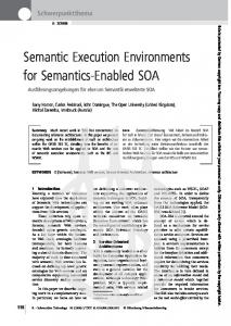
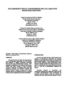
Figure 1: Architectural design review and plant process visualization on our touch table, presented at this year’s CeBIT trade fair.
Abstract Multi-touch interaction on tabletop displays is a very active field of todays HCI research. However, most publications still focus on tracking techniques or develop a gesture configuration for a specific application setup. Very few explore generic high level interfaces for multi-touch applications. In this paper we present a comprehensive hardware and software setup, which includes an X3D based layer to simplify the application development process. We present a robust FTIR based optical tracking system, examine in how far current sensor and navigation abstractions in the X3D standard are useful and finally present extensions to the standard, which enable designers and other non-programmers to develop multi-touch applications very efficiently. CR Categories: H.5.2 [Information Systems]: INFORMATION INTERFACES AND PRESENTATION—User Interfaces Keywords: multi-touch, multi-user, tabletop interaction, X3D
1
Introduction
Today, multi-touch technology is the basis for many new techniques designed to improve interacting with computers. Different subjects have to be taken into account, like e.g. finger and gesture tracking and recognition, software setup and implementation, and also more sophisticated graphical interfaces and interaction principles as well. Developments like Han’s FTIR setup [Han 2005] as well as ∗ e-mail:
[email protected] † e-mail:
[email protected] ‡ e-mail:
[email protected] § e-mail:
[email protected]
Microsoft’s Surface [Microsoft 2008] have inspired this field of research again. Also Apple’s iPhone [Apple 2008] uses this technology to bridge the gap between advanced graphical user interfaces and still limited interaction principles of today’s mobile devices. Multi-touch techniques seem very promising for improving immersion in VR. For most people working on a table feels well known and intuitive, since they are used to work on and around tables every day. Multi-touch technology allows people now to seamlessly interact with what they see by simply touching it. It feels very natural and can lead to more sophisticated interaction. Thus, we chose a table with a monolithic and reduced design and with a huge rear projected high-resolution image of about 150x90 cm, to increase the user’s feeling of immersion. Our goal is to extend the existing X3D ISO standard to enable less experienced developers to rapidly setting up multi-touch capable VR environments. Therefore, we present new abstractions and developments to the current sensor concept and present extensions to the standard interaction and navigation concept of X3D by explaining some concepts of how to interact and navigate in multi-touch environments. Finally the proposed extensions are demonstrated using two different application scenarios. Each application focuses on a different aspect to visualize the various approaches. Our multitouch table (cf. Fig. 1) is based on the total internal reflection (FTIR) setup as shown by Han [Han 2005]. The acrylic sheet of the table is illuminated by IR light, which is totally internal reflected: Whenever a finger touches the surface, the total reflection is frustrated(i.e. light dissipates). A camera, observing the table’s surface, captures the resulting lightblobs. During the tracking process these lightblobs are detected in the camera’s image and events, whether a finger is touching, moving or disappearing, are generated.
1.1
Related Work
¶ e-mail:
[email protected] k e-mail:
[email protected] ∗∗ e-mail:
[email protected] †† e-mail:
[email protected]
In [Dietz and Leigh 2001] a multi-touch table system, the DiamondTouch, was developed for multi-user scenarios and collaborative working. It features simple touch and higher gesture based interaction techniques. Unlike other systems, the finger detection is not vision-based, but a capacitive system is used instead. Using socalled antennas it can also distinguish between different users, and thus provides real multi-user functionality. In [Rekimoto 2002] a sensor architecture based on a capacitive system was introduced, which is sensitive to human hands, finger gestures and also shapes. Rekimoto is also one of the first to show
basic techniques to simultaneously and continuously translate, rotate and scale (2D) objects, and who presents shape-based gestures for object manipulation. A similar approach for continuously transforming objects in order to control Google Earth is also described in [Kim et al. 2007]. The work of [Wu and Balakrishnan 2003] explores various interactions for multi-user tabletop surfaces that leverage and extend the types of multi-finger and whole hand actions people perform when interacting with physical entities on real tables. Not only collaborative actions, but also competitive ones are explored. This approach also works with public and private spaces and is aware of the actions of other users. With his FTIR setup [Han 2005], Han made multi-touch research interesting and public again, since this optical finger detection method is not only low-cost, but also easy to implement and a robust setup not only for tabletop interaction, but also for Wall-like installations. [Jord`a et al. 2007] have developed their ”reacTable”, which mainly uses tangibles for interaction, and is also able to detect multi-user and multi-touch input.
2
Using X3D for Multi-touch Applications
The semantics of the X3D ISO standard describe an abstract functional behavior of time-based, interactive 2D/ 3D multimedia information and do not define a specific interaction device or method. Instead, the specification provides a high-level sensor concept, which transcodes global changes like mouse-pointer position to local persub-graph reactions. The TouchSensor node for instance fires e.g. a local coordinate event through its hitPoint changed eventOut slot while the user ”touches” the marked subtree. [Behr et al. 2004; Behr et al. 2007] showed that the PointingDeviceSensor concept of the ISO standard can be utilized in immersive and/ or multi-user environments by introducing the simple but powerful ”UserBody” extension. The UserBody nodes are ray-intersect or collision triggers for the high-level PointingDeviceSensor instances. In this section we explore how suitable the Sensor and UserBody nodes are for multi-touch environments. We discuss how standard nodes can be interpreted differently and present a new node to provide more multi-touch specific behavior. Probably the most basic form of multi-touch is multi-point interaction. In this regard it seems most natural to extend the X3D PointingDeviceSensor component such that it can also deal with multi-touch events whilst still following the same interaction principles as given in single-touch environments. Before going into detail the concepts of X3D object manipulation as well as necessary extensions are shortly discussed.
2.1
Multiple UserBodies Provide Multiple Pointers
For typical desktop applications, object manipulation and navigation is simply accomplished by using the mouse or similar devices. The X3D PointingDeviceSensor nodes therefore allow to interact with objects in the scene. The user can choose which object to manipulate by locating a pointing device “over” the object. In the case of 2D projections on desktop clients, “over” is defined by moving the mouse pointer over the object’s geometry. Since we have 3D or even 6D devices the X3D specification suggests that the bearing is defined by extending a vector from the current position of the ”pointer” into the direction indicated by the pointer [Web3DConsortium 2008], we have generalized the concept by introducing the UserBody nodes. The “UserBody” is derived from the Group node and defines a subgraph as so-called user body. The children of this grouping node usually consist of geometries that form the shape of the pointer
(for direct visual feedback of pointing tasks). The UserBody additionally has one extra SFBool field “hot”, which is analogous to a mouse button for 2D interaction and corresponds to the “button pressed” state. There can be an arbitrary number of user bodies, e.g. for multi-user and/ or multi-touch applications. The pointer gets transformed in the 3D scene the usual way by putting Transform nodes in the transformation hierarchy above the UserBody and by routing position and orientation values into these Transform nodes. In the previously cited papers it is also shown, how low level sensors, which for instance can receive values from an interaction device, can be used to define the user body transformation. To enable fully immersive interaction via spacemouse or pen we distinguish between different interaction types. These types already were defined in [Behr et al. 2004; Behr et al. 2007], and can be set in the ”interactionType” SFString field of the NavigationInfo node. Whereas the ”ray” mode is suited for CAVE-like environments and handles ray selection completely in 3D (here the ray’s origin is the position of the user body and the ray points into the local negative z direction), the ”projection” mode is especially useful for desktop, PowerWall or table applications. This type also handles ray selection in 3D, but in this case the ray points from the camera through the origin of the user body’s coordinate system. The UserBody in general triggers state-changes in the PointingDeviceSensor nodes. The computer vision based blob tracking approach mentioned above can lead to an arbitrary number of points, which means that user bodies corresponding to those points have to be dynamically created or deleted whenever a new blob is detected or an old one ”left” the scene (i.e. the user removed his finger). For managing the UserBody states we use a simple script that receives all blob positions and IDs (from the computer vision subsystem via low level DataStream sensors), and based on this data either updates the positions of the corresponding user bodies, creates new ones or deletes nodes whose ID is not valid anymore.
2.2
From UserBodies to PointingSensor Behavior
Every UserBody object represents a single tracked finger in world coordinates. There can be an arbitrary number, and the system does not distinguish user bodies, which belong to a specific hand or user. In general, the system therefore supports multi-touch, multi-hand and thus inherently multi-user applications without any additions. However, in most such applications global normalized coordinates per finger are not a sufficient data-model. Most of these applications are interested in more complex relations between those fingers to derive e.g. static or dynamic gestures. Therefore, we first localize the positions by assigning roles to each UserBody, which ray intersects a PointingDeviceSensor’s geometry, and afterwards the geometric or temporal relations are analyzed to trigger a specific behavior. These roles are very simple but powerful. For every PointingDeviceSensor instance there is a dynamic list of user bodies that is sorted by the time how long the intersections already exists. With this list it is simple to request the number of fingers or e.g. attributes for the ’first’ or ’second’ finger. These ’roles’ will be used to trigger the PointingDeviceSensor changes. The standard PointingDeviceSensor nodes are designed with a mouse device in mind; a single position and a single button to trigger state-changes in the sensor. By using the UserBody nodes it is easy to provide the position, but it is still unclear how to click with the fingers. To get around this, two solutions seem equally natural: Touching the same position twice like on a laptop touchpad or activating the sensor with a second finger. We decided to use the latter alternative because on the one hand, the X3D specification states, that an isActive TRUE event is sent upon activation of the pointing device while being over the sensor’s geometry, and on the other
hand it fits into our finger tracking and processing model, because after having removed a finger, the next time it touches the surface again, it receives an other ID. In addition, activating the sensor with a second finger feels quite natural in multi-touch environments and is easy to implement with the provided role-model. Besides using two fingers, it is also possible to already generate the user bodies being ”hot”, which is conceptually the same as holding down the mouse button all the time. Nevertheless, for the user and application developer conceptually both alternatives are important and supported. In contrast to the mouse cursor, in case of the multitouch mode the user bodies aren’t part of the scene until the fingers have touched the surface, and they are automatically removed from the scene after they have left the table. Thus, a bit problematic in this context is only the handling of the ”touchTime” field of the TouchSensor node, because this eventOut is only generated, when the pointing device was – and still is – pointing towards the geometry when it is deactivated. Therefore the touchTime event can only be generated X3D compliant with the help of a second finger: Whereas the first one generates the isOver event, the second one generates the isActive TRUE/FALSE event.
2.3
The HypersurfaceSensor
When thinking about multi-touch interaction in X3D, the easy to use but yet non-standard techniques presented by [Kim et al. 2007; Apple 2008; Microsoft 2008] can be easily mapped to the X3D pointing sensor concept and well known translation/rotation/scaling manipulation functionalities: By putting a finger on an object it can be moved around and with at least two fingers it can be rotated or scaled. However, the multiple pointers or UserBody rays can have different roles, and therefore do not match the current mapping for standard PointingDeviceSensors. Consequently, we propose a new PointingDeviceSensor node, the ”HypersurfaceSensor”, whose interface is shown next. It is also derived from the X3DDragSensorNode, and provides basic translation, rotation and scale outputs for single- and multi-touch applications. HypersurfaceSensor : X3DDragSensorNode { ... SFVec3f [in,out] translationOffset 0 0 0 SFRotation [in,out] rotationOffset 0 0 1 0 SFVec3f [in,out] scaleOffset 1 1 1 SFVec3f [in,out] minScale 0.1 0.1 0.1 SFVec3f [in,out] maxScale 10 10 10 SFVec3f [out] translation_changed SFRotation [out] rotation_changed SFVec3f [out] scale_changed MFVec3f [out] hitNormalizedCoord_changed }
When having activated the sensor’s geometry, it can be moved around with one or more fingers. The different eventOuts (translation changed, rotation changed, scale changed) contain the sum of relative changes plus an offset value. Analog to all PointingDeviceSensor nodes, activation can be done with a single ’hot’ UserBody or a ’second’-role finger. This works quite similar to the PlaneSensor, with the exception, that the plane in which the translation changed events are calculated is parallel to the viewing plane and goes through the initial point of intersection of the first UserBody having touched the sensor’s geometry. Here it can be seen, that it is important that the user bodies are assigned different roles depending on the order they have touched an object. Likewise the rotation changed is a rotation around the axis perpendicular to the viewing plane, and can be achieved by using two fingers/ UserBody nodes, whose initial positions define the axis of zero rotation. Only the scale changed event, which also is activated by using two fingers and whose initial distance defines a scaling of
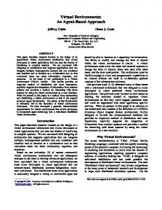
Figure 2: Calculating the translation vector t, the scaling factor s, and the angle α between two succeeding frames (shown in red).
1, sends out a uniform scaling by default, if not restricted via ’minScale’ and ’maxScale’ (the values are ignored if they are smaller than or equal to 0 or if maxScale is smaller than minScale). For all events it is very important for usability, that after having been activated, the sensor remains active until all user bodies have left the scene, and that the initial positions and distances are resetted, if one finger is exchanged against another one and therefore passes his ’role’. Also important for an intuitive user experience and smooth transformations is the fact, that all types of interaction can be obtained concurrently at the same time. Figure 2 sketches, how the resulting transformations can be calculated at once. As described so far, the HypersurfaceSensor uses only up to two fingers to trigger internal state changes and to send new transformation values. Sometimes one might not only be interested in relative, cumulated transformation values but in absolute ones directly. This is already possible with the proposed hitNormalizedCoord changed eventOut slot. The values are sent for all additional fingers, whereas the first two fingers still can keep on manipulating the object or simply holding it. Just like the hitTexCoord changed event of the TouchSensor node they also work in texture space and send out the hit texCoord. This is quite useful in that, with the correct mapping, those values can be used absolutely (see also section 3). Support for 2D and 3D interaction is built into all PointingDeviceSensor nodes and therefore we map the three mouse buttons correspondingly for usage in standard desktop environments. Rotation can be achieved with the left, translation with the middle, and scaling with the right mouse button. Moreover, this sensor works the same way for highly immersive VR environments with the exception that instead of ”projection” the ”ray” ’interactionType’ (as explained above) has to be chosen. By using e.g. two pens, wands or similar input devices, the same interactions are possible here.
3
Applications and Results
The following section describes two applications, which show and demonstrate the proposed changes and extensions. For implementation we have used the InstantReality framework [Avalon 2008]. The ”Virtual Factory Demonstrator” was developed in cooperation with the company Coperion for their appearance at a fair for the plastics industry in Germany. The goal was to present and demonstrate complex processes in a plant for bulk material handling. An overview shows the production line with highlights on important and interactive components. Touching one of the highlights is followed by a smooth camera movement to a close-up. The component becomes transparent and its internal parts and processes become visible (Fig. 1b). Here, the user uses his finger to rotate the camera around the component, which is always centered. With two fingers stretching apart he can zoom onto the component. Some components are interactive themselves. Touching them activates an animation or manipulates the processing’s speed. The complete application was implemented using standard X3D
4
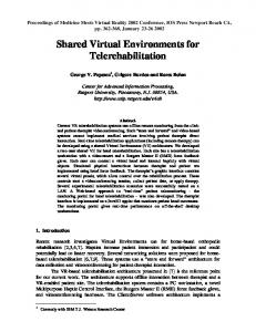
Figure 3: Camera controlling functionality. Left: 2 fingers enable camera control. Middle: 3 fingers control camera position. Right: 4 fingers control camera position and orientation.
PointingDeviceSensor nodes. TouchSensors are used to trigger an action or start a camera flight animation by binding a Viewpoint. CylinderSensor nodes are used to rotate and scale specific subparts of the machinery. UserBodys where sourced ’hot’, thus an additional finger was not needed for activation. However, since the role-list was provided through the hitNormalizedCoord outslot the additional scaling was implemented with the ’second’ finger. The use of standard X3D Sensor nodes enables Coperion to use the application on standard notebooks for their field staff and projections at smaller trade shows and events. The ”Architecture Design Review” application developed for Messe Frankfurt’s new exhibition Hall 11 features scalable architectural 2D blueprints of the building’s floors. Several architects can move and zoom these plans simultaneously, but also navigate through the model of the complex. As described, using the blueprints for navigation is one of the key features of this multitouch application, and additionally an imitation and digital enhancement of an architects native work environment: Working on the multi-touch table is just like they know it from their daily usage of paper plans, except that the application shows a valid real time visualization of the whole building as well. Since only professionals are capable of reading and to imagine the blueprints, one now can see and control a high resolution rendering of blueprints. All plans are simply modeled as textured Plane geometries. Thus, movement, rotation and scaling of the plans work like in common multi-touch applications as described before. With one finger the user simply moves the plan around. While stretching apart two fingers, the blueprints can be scaled and also rotated by describing an angle. Using the HypersurfaceSensor these manipulations are implemented by just routing its results to the Transform node with the corresponding geometry. The real innovation of this application is the navigation through the 3D view of the building. The tile showing the 3D visualization lies on the virtual table next to the blueprints, and is also modeled as a textured plane, because it has to be transformed the same way as the blueprints. But whereas their textures are static, the texture displaying the architectural visualization is dynamically rendered every frame according to virtual camera’s movement. The camera of the 3D visualization is controlled by using simple gestures: The two fingers of the left hand are grabbing a plan, like one would hold a sheet of paper while writing on it. Then, one finger of the right hand points on the construction plan and thus can control the camera movement through the 3D model. Using a second finger of the right hand defines the direction to look at and controls the orientation of the camera (see Fig. 3). When the third finger points on a certain object on the plan and the fourth finger moves around it, the 3D camera moves around that object while keeping it in focus. This feature enables unseen real time cinematic camera movements in 3D that were not possible with previous 3D interaction devices. Now, one can do camera movements like Alfred Hitchcock’s 360◦ camera shot in Vertigo’s ”Transformation of Judy” scene, or the final scene of Brian de Palma’s ”Obsession”, live with fingers and variable radius instead of predefined paths. The result is a much better perception and understanding of otherwise arbitrary looking architectural data within a design review process.
Conclusion and Future Work
In this paper we have presented a comprehensive multi-touch runtime and development system. The proposed application development framework is based on X3D and utilizes the ISO standard for multi-touch environments. The given PointingDeviceSensor component has been discussed and explored. We described how the standard model can be used in multi-touch environments with minimal changes. This proposed role-based extension allows interacting with PointingDeviceSensor nodes with multiple fingers and provides enough flexibility to support an application specific behavior as well. In addition, the HypersurfaceSensor has been proposed, which not just only supports 2D multi-touch environments but is also useful in immersive environments. A set of applications explores and demonstrates the new multi-touch and multi-user extensions. Those applications were demonstrated on different exhibitions and users reported a far more convenient behavior. Future work will focus on the navigation aspect, which can be implemented using the same role based method. But whereas PointingDeviceSensor reactions are application specific, cameranavigation must be handled in the runtime-environment. Another topic will be dynamic gesture recognition systems for triggering commands and for supporting gestures to manipulate application data similar to the current PointingDeviceSensor nodes.
References A PPLE, 2008. Apple iphone. http://www.apple.com/iphone/. AVALON, 2008. Avalon. http://www.instantreality.org/. ¨ B EHR , J., D AHNE , P., AND ROTH , M. 2004. Utilizing x3d for immersive environments. In Web3D ’04: Proc. of the ninth int. conf. on 3D Web technology, ACM Press, NY, USA, 71–78. ¨ B EHR , J., D AHNE , P., J UNG , Y., AND W EBEL , S. 2007. Beyond the web browser - x3d and immersive vr. In IEEE Virtual Reality 2007: Symposium on 3D User Interfaces (3DUI), IEEE, USA. D IETZ , P., AND L EIGH , D. 2001. Diamondtouch: a multi-user touch technology. In UIST ’01: ACM symposium on User interface software and technology, ACM, New York, USA, 219–226. H AN , J. Y. 2005. Low-cost multi-touch sensing through frustrated total internal reflection. In UIST ’05: ACM symposium on User interface software and technology, ACM, NY, USA, 115–118. J ORD A` , S., G EIGER , G., A LONSO , M., AND K ALTENBRUNNER , M. 2007. The reactable: exploring the synergy between live music performance and tabletop tangible interfaces. In TEI ’07: Int. conf. on Tangible and embedded int., ACM, NY, 139–146. K IM , J., PARK , J., K IM , H., AND L EE , C. 2007. Hci(human computer interaction) using multi-touch tabletop display. Communications, Computers and Signal Processing, 2007. PacRim 2007. IEEE Pacific Rim Conference on, 391–394. M ICROSOFT, 2008. Surface. http://www.microsoft.com/surface/. R EKIMOTO , J. 2002. Smartskin: An infrastructure for freehand manipulation on interactive surfaces. In SIGCHI conf. on Human factors in computing systems, 113–120. W EB 3DC ONSORTIUM. 2008. X3D. http://www.web3d.org/x3d/ specifications/ISO-IEC-FDIS-19775-1.2/index.html. W U , M., AND BALAKRISHNAN , R. 2003. Multi-finger and whole hand gestural interaction techniques for multi-user tabletop displays. In ACM Symposium on User Interface Software and Technology, ACM Press, Vancouver, Canada, UIST 2003, 192–202.