Indian Journal of Geo Marine Sciences Vol.46 (12), December 2017, pp. 2562-2571
Adaptive circular path following control of a mini-AUV prototype Xianbo Xiang1, Hui Liu1, Zongtong Luo1 & Qin Zhang2* 1
School of Naval Architecture and Ocean Engineering, Huazhong University of Science and Technology, Wuhan 430074, P. R. China 2 School of State Key Laboratory of Manufacturing Equipment and Technology, School of Mechanical Science and Engineering, Huazhong University of Science and Technology, Wuhan 430074, P. R. China *[E-mail:
[email protected]] Received 17 April 2017 ; revised 28 October 2017
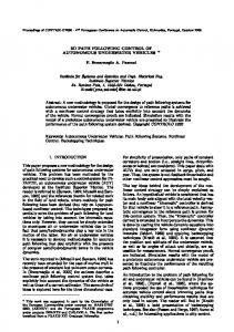
This paper proposed a controller based on line-of-sight (LOS) guidance and Lyapunov theory for a mini autonomous underwater vehicle (AUV) prototype, to address the problem of adaptive circular path following in clockwise or anti-clockwise direction. First, the overall structure of the mini-AUV system is briefly presented with the hardware components and the software design. Second, the guidance rule and the controller design for the straight-line following and the adaptive circular path following in clockwise or anti-clockwise are formulated in detail. Subsequently, the numerical and experiment results are performed to demonstrate the performance of the motion capability of the vehicle and the effectiveness of the proposed control algorithms.
[Keywords: mini-AUV, circular path following, guidance and control, line-of-sight]
Introduction As one branch of marine robotics, mini-AUV plays an important role in marine science, ocean industry and engineering education, commercial products and many other applications, such as oceanographic research1, resource exploration2, tracking and inspection of subsea cable3, seawater sampling4,5 ocean observation and seafloor mapping6,7. However, as one of the motion control problems, path following of the underwater vehicle still remains a challenging mission mainly because of the non-linear dynamics, under-actuated
* Corresponding author
configuration, uncertainties in hydrodynamics and presence of wave and current 8,9,8,9,10 disturbances . Many approaches have been proposed to solve the AUV motion control problems, such as metaheuristics algorithms including genetic algorithm and neural network13,14,13,14. However, neural network cannot avoid the off-line learning in advance or on-line learning to get the weight adjustments to ensure the good performance. Whereas, the genetic algorithm needs significant time for the crossover and mutation iterations,
INDIAN J. MAR. SCI., VOL. 46, NO. 12, DECEMBER 2017
due to the complex encoding and decoding calculation process. In addition, the stability of such controllers cannot be ensured easily. The implement of these algorithms on the AUVs is rather challenging due to the expensive development and field experiment 16,18,19,20,21,22 costs . Furthermore, these algorithms are commonly based on the accurate model of the designed vehicle, and the performance is usually determined by the accuracy of the parameters for model identification23,24,25,26,27,28. Considering the problems mentioned above, a mini-AUV with easy automatic motion control function and cheap price is developed in the Lab of Autonomous Robotic Marine Systems (ARMs) in Huazhong University of Science and Technology. It becomes more realistic to achieve these proposed methods or controller in the mini-AUV platform. Furthermore, the cost of field experiments for mini-AUV is reduced to acceptable range and it is quite convenient to carry out the field tests in lakes or the swimming pool. For the motion control problems, AUVs are usually required to follow and then converge to a predefined geometric path without temporal constraints, which is more popular and easier to be implemented on AUVs compared with trajectory tracking29,30,31,32,33,34. In this paper, two typical paths are chosen for the mini-AUV to follow, the straight-line and the circular path. As for the control objective, the controller should calculate the control inputs according to the algorithm, which can make both the course tracking error and cross track error reduce to zero. In this case, the vehicle should keep along with the desired path with the resultant speed of the vehicle in tangent direction of the path. To achieve this objective, the LOS guidance based on Lyapunov theory is adopted in the Serret-Frenet frame to guide the mini-AUV to move towards the desired path35,36,37. The PID
2563
controller can steer the orientation of the mini-AUV to the desired guidance angle without velocity measurement and feedback control. The simulation and experiment results demonstrate the performance in stabilizing both the course tracking error and the cross track error of the vehicle. Materials and Methods This section briefly introduces the system configuration of the mini-AUV prototype, including the overall structure and the software design. Mini-AUV structure The overall structure of the mini-AUV system is presented in Figure 1. The mini-AUV is equipped with simple actuators which include one main propeller, a rudder and an elevator as well as a water pump. To obtain the position and the posture information, an Initial Navigation System sensor (INS) and a Global Positioning System (GPS) model are also equipped on the vehicle. The sensor data is transmitted by RS232 interface with the onboard controller (STM32F103). The surface monitoring station operates on a computer with windows platform. By using of the ZigBee technology, the onboard controller can communicate with the surface monitoring station easily and steadily.
Fig. 1- Mini-AUV structure
2564
XIANG et al.: ADAPTIVE CIRCULAR PATH FOLLOWING CONTROL OF A MINI-AUV PROTOTYPE
Software design The software design of the mini-AUV system is depicted in Figure 2.
error should be reduced to zero. In order to fulfill the control objectives, the guidance and control algorithms for straight-line and circular path are designed as follows.
Fig. 2- Software design for the mini-AUV
The software of surface monitoring and control station is mainly divided into four parts: the display module, the command module, the storage module and the communicate module. The display module provides the function of displaying the desired path and the AUV path in real-time. The AUV state parameters such as the position, heading angle, speed, rudder, and other operating parameters are also updated and displayed in this model; the command module is the key part of this software, which includes the open-loop and closed-loop control modes, and the proposed path following controller based on Lyapunov theory and LOS method is embedded; the storage module is responsible to save all the operating data of the vehicle, such as the position, heading angle, speed and some other data; finally, the communicate module offers the communication access to the cloud server and the onboard control unit. Guidance and control The guidance and control algorithm based on Lyapunov theory is introduced in this section. In order to validate the motion capability and proposed controller, two typical paths are chosen to be followed, the straight-line and the circular path. As for the path following control objectives, both the course tracking error and the cross-track
Fig. 3- Posture error model
As presented in Figure 3, the corresponding earth-fixed position and Euler angle vector of the vehicle is defined as p ( x, y, )T , and the reference vector of the virtual vehicle moving on the path is pr ( xr , yr , r ) T . The cross-track error and course tracking error in the earth-fixed frame can be expressed as ( FB) I (OB) I (OF ) I
(1)
By taking rotation transformation, the error can be rewritten as ( FB) F RIF ( FB) I RIF ((OB) I (OF ) I ) (2) where RIF is the rotate matrix from {I} to {F}, and the matrix can be written as
cos r R sin r 0 F I
sin r cos r 0
0 0 1
(3)
Then the error pe ( xe , ye , e )T can be written as
xe cos r y sin r e e 0
sin r cos r 0
0 x xr 0 y yr 1 r
(4)
INDIAN J. MAR. SCI., VOL. 46, NO. 12, DECEMBER 2017
A. Straight-line path following To make the vehicle follow the desired straight-line path, the error is calculated in the Serret-Frenet frame. The origin of the frame is set at the projective point in the desired path, such that xe 0 , which is illustrated in Figure 4.
2565
ye (9) where is a constant according to the shape of the vehicle. Usually, the value is about two
LOS arctan
times of the vehicle’s length. LOS is the guidance angle only determined by the cross-track error ye . If e LOS , then V can be expressed as y (10) V u ye sin(arctan e ) 0 Since V 0 and V 0 , then V 0 , which means ye and e 0 . So the vehicle can follow the desired path as expected. Hence the
course tracking error Be can be expressed as Fig. 4- Straight-line path following
To follow the path, a Lyapunov candidate function for the cross-track error is constructed as
1 2 ye 2 The derivative of V can be written as V (Ye )
V ye ye
(5)
(6)
Based on Equation (4), the error dynamics equations can be expressed as xe r ye ur u cos r y x u sin r e e e e r
Be W r LOS r arctan
ye
where W is the guidance angle in the earth-fixed frame. B. Adaptive circular path following As for the circular path, the key task is designing the guidance angle LOS according to the cross-track error along the circular path. The circular path following is presented in Figure 5.
(7)
where u and denote the surge and yaw velocities with coordinates in the body-fixed frame, while ur and r is the surge and yaw velocities of the reference vehicle. In the Serret-Frenete frame, the error xe 0 , then y e reduces to ye u sin e
(11)
(8)
To reduce e and ye , the LOS guidance angle is defined as Fig. 5- Circular path following
2566
XIANG et al.: ADAPTIVE CIRCULAR PATH FOLLOWING CONTROL OF A MINI-AUV PROTOTYPE
The cross-track error of the circular path following can be expressed as ye R d B
(12)
where R is the radius of the target circle and d B ( x xo )2 ( y yo )2 is the distance between the origin of the circle and the center of the vehicle. Therefore, the guidance angle LOS for circular path can be written as R dB (13) LOS arctan The course tracking error Be can be expressed as
Be W r LOS r arctan
(14)
R dB
y is updated by the x 2 real-time position of the vehicle.
where r arctan
Finally, the PID controller to control the rudder angle can be written as rPID K p Be K I Be dt K D Be
(15)
For the circular path following, if the guidance angle LOS is calculated by considering the equation (13), the mini-AUV will follow the path along the clockwise direction illustrated by the blue line in Figure 6. As the vehicle starts with the initial heading angle in the left side of the symmetrical line (a straight line passing through the center of a circle and the gravity center of the vehicle), the clockwise direction based on the traditional guidance law is not a smart choice. If the vehicle could adaptively follow the path along the anti-clockwise direction illustrated by the red line, less time and energy would be consumed for this circular path following mission.
Fig. 6- Adaptive circular path following
As mentioned above, an adaptive circular path following method based on the guidance angle LOS is proposed as LOS , LOS 0 LOS , LOS 0
LOS
(16)
It means if the vehicle starts the circular following task with the heading angle in the left side of the symmetrical line, the guidance angle LOS will be automatically transformed into by taking the adaptive direction control LOS method, and then the vehicle will follow the circular path in anticlockwise direction.
Results and Discussion This section provides the simulation and experiment results of the developed vehicle system and the proposed guidance and control algorithms. The simulation and experiments are performed in two cases: the straight-line following case and the circular case. The simulation and experiment parameters are listed in Table 1. Table-1 Simulation and experiment parameter
△
1.5
u
0.03ms-1
Kp
0.4
KI
0
KD
0.4
INDIAN J. MAR. SCI., VOL. 46, NO. 12, DECEMBER 2017
Straight-line path following In Figure 7 and Figure 8, the results of simulation and experiment of the straight-line path following are illustrated. The tracking path, cross-track error ( ye ) and the heading angle of the vehicle are presented in the first, second and third subplot, respectively.
Y(m)
2
0
1
2
3
4
5 X(m)
6
7
8
9
10
2
Ye(m)
1 0 -1
0
10
20
30 t(s)
40
50
60
following
ye
error
is
about
0
with
ψ(°)
50 0
0
10
20
30 t(s)
40
50
60
Fig. 7- Simulation result of straight-line path
As shown in Figure 7, the vehicle can follow the desired straight-line y 2 well in 20 seconds. The vehicle starts from the initial position and heading angle vector of ps (0,0,0 )T and ends with the state of pe (8,2,0 )T . The green line shows the heading angle and the maximum angle is 69.3 during the path following stage.
environmental disturbance. After 25 seconds, the heading angle goes back to 0 and successfully keeping along with the target line y 2 . The convergence speed in the experiment is slower than that in simulation ones, so it takes more time to reach the expected state.
Circular path following A. Anticlockwise path following The simulation results of anticlockwise circular path following is shown as Figure 9 and 10.
means the initial heading angle is on the left side of the symmetrical line of the circle, so the anticlockwise would be the right direction for the following task. In this case, the vehicle is required to follow the circle with its origin at (0,1.5) , and its radius equals 2 meters. The cross-track error ye gradually reduces to 0 after 23 seconds, then it maintains at zero steadily. The green line presents the heading angle during the circular path stage, which belongs to [180 ,180 ] . 4
Y(m)
2 Desired path
3
AUV trajectory 0
1
2
3
4 X(m)
5
6
7
2.5
8
2 Y(m)
2 Ye(m)
Desired path AUV trajectory
3.5
1 0
1
1.5
0
1
-1
0.5
0
5
10
15
20
25 t(s)
30
35
40
45
50
0
100 ψ(°)
the
The vehicle starts following the circular path with the initial state of p (0,0,0)T , which
100
-50
In Figure 8, the vehicle is able to also follow the desired path as expected in the experiment test. The
Desired path AUV trajectory
1 0
2567
-0.5
50
-1 -2.5
0 -50
0
5
10
15
20
25 t(s)
30
35
40
45
-2
-1.5
-1
-0.5
0 X(m)
0.5
1
1.5
2
50
Fig. 8- Experiment result of straight-line path
Fig. 9- Simulation result of circular path (Path plot)-Anticlockwise
2.5
2568
XIANG et al.: ADAPTIVE CIRCULAR PATH FOLLOWING CONTROL OF A MINI-AUV PROTOTYPE
0.5
0.2 Ye(m)
Ye(m)
0.4
0
0
-0.2 0
10
20
30
40
50
60
70
80
-0.5
90
180
180
120
120
60
60 ψ(°)
ψ(°)
t(s)
0
-60
-120
-120
0
10
20
30
40
50
60
70
80
-180
90
10
20
30
40 t(s)
50
60
70
80
0
-60
-180
0
0
10
20
30
t(s)
40
50
60
70
t(s)
Fig. 10- Simulation result of circular path
Fig. 12- Experiment result of circular path
(Error and heading angle plot)-Anticlockwise
(Error and heading angle plot)-Anticlockwise
In the experiment test as shown in Figure 11 and 12, due to the existence of side-slip angle and without error integral control, the cross-track error is always existed with the value of about 0.03m, which is in acceptable accuracy. If the initial state of the vehicle is set with heading angle in the right side of the symmetrical line of the circle, the clockwise direction will be chosen by the vehicle.
B. Clockwise path following The simulation and experiment results with the initial state of the heading angle in the right side of the symmetrical line of the circle are illustrated in Figure 12-15. 4 Desired path 3.5
AUV trajectory
3 4 Desired path
2.5
AUV path
3.5
2 Y(m)
3 2.5
1
2
Y(m)
1.5
1.5
0.5
1
0
0.5
-0.5
0
-1 -2.5
-0.5 -1 -2.5
-2
-1.5
-1
-0.5
0 X(m)
0.5
1
1.5
2
2.5
-2
-1.5
-1
-0.5
0 X(m)
0.5
(Path plot)-Anticlockwise
1.5
Fig. 13- Simulation result of circular path (Path plot)-Clockwise
Fig. 11- Experiment result of circular path
1
2
2.5
2569
INDIAN J. MAR. SCI., VOL. 46, NO. 12, DECEMBER 2017
0.6 0.4 Ye(m)
Ye(m)
0.4 0.2
0.2 0
0 0
10
20
30
40
50
60
70
80
-0.2
90
0
10
20
0
10
20
30
180
180
120
120
60
60 ψ(°)
ψ(°)
t(s)
0
-60
-120
-120 0
10
20
30
40
50
60
70
80
90
-180
t(s)
60
70
30
40 t(s)
50
60
Fig. 16- Experiment result of circular path
(Error and heading angle plot)-Clockwise
(Error and heading angle plot)-Clockwise
4 Desired path AUV trajectory
3.5 3 2.5 2 1.5 1 0.5 0 -0.5 -1 -2.5
-2
-1.5
-1
-0.5
0 X(m)
0.5
1
1.5
2
2.5
Fig. 15- Experiment result of circular path (Path plot)-Clockwise
In the clockwise circular path case, the vehicle can still successfully follow the target circle in both simulation and experiment tests, as shown in Figure 13 and 15. It is worth noting that no matter clockwise or anticlockwise case, the side-slip angle is always existing in the experiment tests as shown in Figure 12 and 16,
80
70
Fig. 14- Simulation result of circular path
The vehicle starts following the target circle with the initial state of p (0,0,180)T , which means the clockwise direction is the right choice for this case. The mini-AUV follows the circular path in clockwise as illustrated in the simulation result.
Y(m)
50
0
-60
-180
40 t(s)
which means the integral part in the controller can be instrumental to account for the environmental disturbances.
Conclusions This paper proposes a path following controller based on LOS guidance and Lyapunov theory, which is implemented in a mini-AUV prototype developed in the ARMs lab. The surface monitoring and control station operates at a remote computer. To verify the motion capability and proposed controller of the mini-AUV, the numerical simulation and field experiment are performed. The numerical and experimental results demonstrate the performance of the whole mini-AUV system and the proposed controller for both straight-line and adaptive circular path following. Future work will include the improvement of the path following controller to account for environment disturbances.
Acknowledgment This work is partially supported by National Natural Science Foundation of China [under Grant 51579111 and Grant 51209100], the Fundamental Research Funds for the Central Universities [under Grant 2017KFYXJJ005],
2570
XIANG et al.: ADAPTIVE CIRCULAR PATH FOLLOWING CONTROL OF A MINI-AUV PROTOTYPE
State Key Laboratory of Ocean Engineering [under Grant 1504], and International Exchanges of the UK Royal Society [under Grant IE161588].
16
17
References 1
2
3
4
5
6
7
8
9
10
11
12
13
14
15
Zhou, L., Cheng, X.H., Zhu, Y.X., Dai, C.X., & Fu, J.B., An effective terrain aided navigation for low-cost autonomous underwater vehicles, Sensors, 17(2017) 680. Ohta, Y., Yoshida, H., Ishibashi, S., Sugesawa, M., Fan, F. H., & Tanaka, K., Seabed resource exploration performed by AUV ―Yumeiruka‖. In OCEANS 2016 MTS/IEEE, Monterey, 2016. Xiang, X.B., Yu, C.Y., Niu, Z.M. & Zhang, Q., Subsea cable tracking by autonomous underwater vehicle with magnetic sensing guidance, Sensors, 16(2016) 1335. Pennington, J. T., Blum, M., & Chavez, F. P., Seawater sampling by an autonomous underwater vehicle:―Gulper‖ sample validation for nitrate, chlorophyll, phytoplankton, and primary production, Limnol Oceanogr-Meth, 14(2016) 14-23. Xiang, X.B., Yu, C.Y., Zheng, J.R. & Xu, G.H., Motion forecast of intelligent underwater sampling apparatus—Part I: Design and algorithm, Indian J. Mar. Sci., 44(2015) 1962-1970. Kadir, H. A., & Arshad, M. R., Ocean Observation System using Multi Blimp System with Animal inspired Consensus Decision Making, Indian J. Mar. Sci., 44(2015) 1951-1961. Cui, R.X., Chen, L.P., Yang, C.G. & Chen, M., Extended state observer-based integral sliding mode control for an underwater robot with unknown disturbances and uncertain nonlinearities, IEEE Trans. Ind. Electron., 64(2017) 6785-6795. Xiang, X.B., Yu, C.Y., Zhang, Q., & Xu, G.H., Path-following control of an auv: Fully actuated versus under-actuated configuration, Mar. Technol. Soc. J., 50(2016) 34-47. Xiang, X.B, Lapierre, L., & Jouvencel, B., Smooth transition of AUV motion control: From fully-actuated to under-actuated configuration, Robot Auton. Syst., 67(2015) 14-22. Isa, Khalid; Arshad, M.R., Modeling and motion control of a hybrid-driven underwater glider, Indian J. Mar. Sci., 42(2013) 971-979. Xiang, X.B., Yu, C.Y., & Zhang, Q., Robust fuzzy 3d path following for autonomous underwater vehicle subject to uncertainties, Comput. Oper. Res., 84(2017) 165-177. Mei, J. H., Arshad, M. R., Hybrid artificial potential field method for autonomous surface vessel path planning in dynamic riverine environment, Indian J. Mar. Sci., 44(2015) 1995-2007. Zhu, D.Q., Hua, X., & Sun, B., A neurodynamics control strategy for real-time tracking control of autonomous underwater vehicles, J. Navigation, 67(2014) 113-127. Do, K.D., Path-tracking control of underactuated ships under tracking error constraints, J. Marine Sci. Appl., 14(2015) 343-354. Chu, Z.Z., Zhu, D.Q. & Yang, S.X., Observer-based adaptive neural network trajectory tracking control for
18
19
20
21
22
23
24
25
26 27
28
29
30
31
remotely operated vehicle, IEEE T. Neur. Net. Lear., (in press), 2016, DOI: 10.1109/TNNLS.2016.2544786. Xiang, X.B., Yu, C.Y. & Zhang, Q., On intelligent risk analysis and critical decision of underwater robotic vehicle, Ocean Eng., 140(2017) 453–465. Liu, H., Wang, B.H., & Xiang, X.B., Adventure-I: A mini-AUV prototype for education and research. In Autonomous Underwater Vehicles (AUV), Tokyo, 2016. Xiang, X.B., Yu, C.Y., Lapierre, L., Zhang, J.L. & Zhang, Q., Survey on fuzzy-logic-based guidance and control of marine surface vehicles and underwater vehicles, Int. J. Fuzzy Syst. (in press), 2017, DOI: 10.1007/s40815-017-0401-3. Yu, C.Y., Xiang, X.B, Zhang, Q. & Xu, G.H., Adaptive fuzzy trajectory tracking control of an under-actuated autonomous underwater vehicle subject to actuator saturation, Int. J. Fuzzy Syst. (in press), 2017, DOI: 10.1007/s40815-017-0396-9. Yu, C.Y., Xiang, X.B., Lapierre, L. & Zhang, Q., Robust magnetic tracking of subsea cable by AUV in the presence of sensor noise and ocean currents, IEEE J. Oceanic Eng. (in press), 2017, DOI: 10.1109/JOE.2017.2768105. Kang, H.S., Kim, M.H., Bhat Aramanadka, S.S., Kang, H.Y. & Lee, K.Q., Suppression of tension variations in hydro-pneumatic riser tensioner by using force compensation control, Ocean Syst. Eng., 7(2017) 225-246. Aguiar, A. P., & Hespanha, J. P., Trajectory-tracking and path-following of underactuated autonomous vehicles with parametric modeling uncertainty, IEEE T. Automat. Contr., 52(2007) 1362-1379. Zhang, L., Jouvencel, B., Fang, Z. & Xiang, X.B., 3D reconstruction of seabed surface through sonar data of AUVs, Indian J. Mar. Sci., 41(2012) 509-515. Encarnação, P., & Pascoal, A., Combined trajectory tracking and path following: an application to the coordinated control of autonomous marine craft, In Decision and Control, 2001. Xiang, X.B, Liu, C., Su, H.S. & Zhang, Q., On decentralized adaptive full-order sliding mode control of multiple UAVs, ISA Trans. (in press), 2017, DOI: 10.1016/j.isatra.2017.09.008. Lapierre, L. & Soetanto, D., Nonlinear path-following control of an AUV, Ocean Eng., 34(2007) 1734-1744. Gao, J., & Liu, C., Nonlinear adaptive path following control of an autonomous surface vehicle: Theory and experiments, Indian J. Mar. Sci., 44 (2015) 1669-1677. Yu, C.Y., Xiang, X.B., Lapierre, L. & Zhang, Q., Nonlinear guidance and fuzzy control for three-dimensional path following of an underactuated autonomous underwater vehicle, Ocean Eng., 146(2017) 457–467. Peng, Z.H., Wang, J. & Wang, D., Containment maneuvering of marine surface vehicles with multiple parameterized paths via spatial–temporal decoupling, IEEE/ASME Trans. Mechatron., 22(2017) 1026-1036. Wang, N., Sun, J.C., Han, M., Zheng, Z.J. & Er, M.J., Adaptive approximation-based regulation control for a class of uncertain nonlinear systems without feedback linearizability, IEEE Trans. Neural Newt. Learn. Syst., (in press), 2017, DOI: 10.1109/TNNLS.2017.2738918. Zhang, Q., Lapierre, L. & Xiang, X.B., Distributed
INDIAN J. MAR. SCI., VOL. 46, NO. 12, DECEMBER 2017
control of coordinated path tracking for networked nonholonomic mobile vehicles, IEEE Trans. Ind. Inform., 9(2013) 472-484. 32 Chu, Z.Z., Xiang, X.B., Zhu, D.Q., Luo, C.M. & Xie, D., Adaptive fuzzy sliding mode diving control for autonomous underwater vehicle with input constraint, Int. J. Fuzzy Syst. (in press), 2017, DOI: 10.1007/s40815-017-0390-2. 33 Zheng, Z.W., Jin, C., Zhu, M. & Sun, K.M., Trajectory tracking control for a marine surface vessel with asymmetric saturation actuators, Robot. Auton. Syst., 97(2017) 83–91. 34 Wang, N., Su, S.F., Yin, J.C., Zheng, Z.J. & Er, M.J., Global asymptotic model-free trajectory-independent tracking control of an uncertain marine vehicle: An adaptive universe-based fuzzy control approach, IEEE
2571
Trans. Fuzzy Syst. (in press), 2017, DOI: 10.1109/TFUZZ.2017.2737405. 35 Zheng, Z.W, Huang, Y.T., Xie, L.H. & Zhu, B., Adaptive trajectory tracking control of a fully actuated surface vessel with asymmetrically constrained input and output, IEEE Trans. Control Syst. Technol. (in press), 2017, DOI: 10.1109/TCST.2017.2728518. 36 Peng, Z.H., Wang, J. & Wang, D., Distributed containment maneuvering of multiple marine vessels via neurodynamics-based output feedback, IEEE Trans. Ind. Electron., 64(2017) 3831-3839. 37 Fossen, T.I. & Lekkas, A.M., Direct and indirect adaptive integral line-of-sight path-following controllers for marine craft exposed to ocean currents, Int. J. Adapt. Control Signal Process., 31(2017) 445-463.