controller is designed hierarchically with command filters, where the first order ... disturbances in hypersonic flight under limited control surface deflection.
MATEC Web of Conferences 151, 05004 (2018) https://doi.org/10.1051/matecconf/201815105004 ACMAE 2017
Adaptive Command Filtered Integrated Guidance and Control for Hypersonic Vehicle with Magnitude, Rate and Bandwidth Constraints Liang Wang, Weihua Zhang, Ke Peng and Donghui Wang National University of Defense Technology, College of Aeronautics and Astronautics, 410073 Changsha, China
Abstract. This paper proposes a novel integrated guidance and control (IGC) method for hypersonic vehicle in terminal phase. Firstly, the system model is developed with a second order actuator dynamics. Then the back-stepping controller is designed hierarchically with command filters, where the first order command filters are implemented to construct the virtual control input with ideal states predicted by an adaptive estimator, and the nonlinear command filter is designed to produce magnitude, rate and bandwidth limited control surface deflection finally tracked by a terminal sliding mode controller with finite convergence time. Through a series of 6-DOF numerical simulations, it‟s indicated that the proposed method successfully cancels out the large aerodynamics coefficient uncertainties and disturbances in hypersonic flight under limited control surface deflection. The contribution of this paper lies in the application and determination of nonlinear integrated design of guidance and control system for hypersonic vehicle.
1 Introduction Hypersonic vehicle has the potential to fulfill the role of fast-speed and long-range aircraft capable to reach anywhere in a few time. The typical configuration is a wedge-shaped lifting body with a scramjet engine, which produces severe coupling of aerodynamics forces. So the hypersonic flight control is always a challenging research area. The guidance and control system needs to deal with large flight envelop, aerodynamics coefficients uncertainties, as well as flight states coupling (see [1, 2]). The conventional design of the guidance and control system contains two hierarchical loops. In this manner, the inner autopilot loop is designed as a solution to track the angle of attack (AOA) or acceleration command generated by the outer guidance loop. The inner and outer control laws are independently designed based on frequency separating approximation. However, the approximation does not hold in hypersonic flight due to the rapid change of flight states. The conventional design may cause instability and increase the steady error. The integrated approach can eliminate the time lag existing inevitably in the conventional design, and exploit fully the synergistic relationships between guidance and control system. On one hand, the design process and cost can be significantly reduced. On the other hand, the performance of the flight control system is potential to improve. In [3], the term “integrated” means that the nonlinear flight dynamics is built without states separation and the full-state feedback generates directly the fin deflections. In this case, the guidance law and autopilot control law is designed together. The term also means the guidance law is independently designed with full-state feedback. In [4], it was shown that the performances of both
two full-state feedback designs were superior to separated design. In [5, 6], a two-loop controller structure of partial integrated guidance and control is proposed. The outer loop is designed to generate the pitch angle rate command not AOA or acceleration command, and the inner loop tracks the outer loop command. For cascade nonlinear integrated guidance and control, it‟s very useful to recursively design indirect (or pseudo, virtual) control input for lower dimension subsystems step by step so as to deal with the un-matched uncertainties and disturbances in different channels. The studies and examples of this back-stepping technique in the case of integrated guidance and control are found in [7, 8]. However the backstepping controllers suffer from the problem of repeated differentiation of the virtual control input, which results in signal chattering. Hou [7] employ low-pass command filter to avoid directly differentiating to each virtual control input for missile integrated guidance and control system. In [7-11], the employment of command filter in back-stepping control is presented as „dynamic surface control‟ (DSC) technique. It is widely extended in hypersonic flight control issues. In [12], the second-order command filters instead of the firstorder filters are applied in DSC. With the help of command filters, the performance of back-stepping controller is significantly improved in stability and steady-state tracking accuracy, and the detail analysis is made in [13]. In [14], the stability of command filtered back-stepping control is further improved by composite learning. In [15, 16], a linear second order command filter is designed to impose magnitude and rate limitations on one of the virtual control input. In [17], the global uniform ultimate boundlessness of the tracking errors in DSC is guaranteed in the presence of the input constraints. Deep discussion about control input
© The Authors, published by EDP Sciences. This is an open access article distributed under the terms of the Creative Commons Attribution License 4.0 (http://creativecommons.org/licenses/by/4.0/).
MATEC Web of Conferences 151, 05004 (2018) https://doi.org/10.1051/matecconf/201815105004 MATEC Web of Conferences ACMAE 2017
constraint, finite time convergence in IGC design arises rapidly in [18-20]. In [20], first order auxiliary dynamics is developed to deal with the input constraints. As opposed to non-adaptive control method, adaptive control allows for performance over a wider flight envelope and uncertain operational environment such as actuator failure or unexpected changes of flight dynamics. In [21], L1 adaptive control architecture (as shown in Figure 2) is C s offers great introduced, where the command filter benefit in filtering the plant uncertainties. The features have been verified in a large number of flight tests in recent papers. It is a powerful and low-cost controller in the presence of large uncertainties, un-modeled dynamics, and disturbances. In [22, 23], output feedback L1 adaptive control is designed and applied to missile guidance and control system. It demonstrates robustness to significant changes in the missile dynamics up to ±50% change in the missile longitude model parameters. In [24], the application of L1 adaptive control for hypersonic re-entry is presented. The reference AOA command is generated by a slower outer-loop flight path angle PID controller. Several scenarios including degradation of control surface efficiency, reduced longitudinal stability margins and controller processing delays are simulated without controller reconfiguration to test the robustness. In [25-28], it mainly addresses the application of L1 adaptive control in IGC design for hypersonic glider. A dynamics pole placement controller is implemented as the baseline controller, and it is augmented with an L1 adaptive controller to cancel out the matched and unmatched uncertainties. Motivated by the reviews and discussions on the integrated guidance and control design, the adaptive command filtered controller is proposed for IGC of hypersonic vehicle in terminal phase. This paper is organized as follows: In Section 2, the nonlinear IGC model is built with uncertain aerodynamics parameters and unmatched time-varying disturbances. In Section 3, the adaptive IGC controller based on command filter and backstepping technique is introduced, the control law is derived. In Section 4, the numerical simulations of different scenarios are presented. The system dynamics of more general types including time and state dependent nonlinearities are tested. In Section 5, the paper is concluded.
Y nM
q
local horizental
V
R line of sight
xt
x0
X
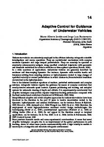
Figure 1. The planar geometry in terminal phase
2.1 Longitudinal Dynamics The nonlinear longitudinal flight dynamics is presented as follows:
R V cos q q
V sin q R
Lo L
g cos V
Mo M z z
(1a) (1b) (1c) (1d)
when the flight velocity is high, the lift force coefficient C CL CLo C can be expressed as L . L is the lift S coefficient derivative with respect to AOA, ref is the aerodynamics reference size, V is approximated as constant velocity, m, g are constant mass and gravity acceleration. L L Lo . Then the lift consists of two parts:
L
2 Problem Formations
Lo
where
L Lo 1 1 VSref CL , Lo = VSref CLo mV 2 mV 2 (2) L
is the main contribution of AOA to lift, and
means the other factors contribution to lift such as control surface and body. Then the two parts of lift are unified by momentum. The aerodynamics moment is also described in two parts:
In this section, the nonlinear IGC model is developed. The aerodynamics coefficients are taken from a scaled down version of NASA‟s CAV (see Appendix A). The planar geometry in terminal phase is placed in Figure 1. The inertial coordinate system OXY is built without considering the earth rotation, OX axis is local horizontal. R is the distance between mass center and landing point. q, , z are respectively the LOS (Line of Sight) angle, AOA and pitch angle rate. The angle and angle rate directions shown in Figure 1 are positive.
M z M z z M o
M
z , is the moment coefficient derivative with respect to control surface deflection, and Mo means the other factors contribution to moment. Both are unified by the moment of inertia with respect to z-axis Iz .
Mo
2
Mz Mo , Mz Iz Iz
(3)
MATEC Web of Conferences 151, 05004 (2018) https://doi.org/10.1051/matecconf/201815105004 ACMAE 2017 ACMAE 2017
f t, x , i 1, 2, 3 that i are uniform bounded and partial derivatives are semi-global uniform bounded. Then the following upper bound is yielded:
Next, the actuator dynamics is integrated with the vertical flight dynamics. This paper considers a second order actuator dynamics is given by the following transfer function:
z s K act zc s Tact2 s 2 2Tactact s 1
G act s
where
f i x, t
(4)
z is the control surface deflection, and K z , T z ,
are respectively mean the constant gain, the time constant,
where
2.2 Integrated Guidance and Control Differentiating (1b) respect to time, together with (1c) yields:
R g 2q cos L Lo R V
Lr x
L
B
(5)
Lr
fi t, x i t x t
i t , i 1, 2, 3
T
t , t , i 1, 2, 3 are unknown time-varying where i i functions subject to:
x1 x2 f1 d1 x2 x3 f 2 d 2
t , t d
x3 bx4 f 3 d 3
t b , t d
x4 x5 x f act f act bact u d act 5
Then the IGC system can be approximated as follows:
aerodynamics uncertainties, f act t, x is a linear function
x1 1 x
derived by the actuator transfer function, and f act t means
its uncertain part. di t , i 1, 2, 3 and d act t are timevarying disturbances in different channels.
R g R f1 x 2 x1 cos Lo L x2 R V R
(7a)
g cos L x2 Lo V
(7b)
f3 x M x2 M x3 , b M 2 1 f act x Kact 2 x4 act x5 , bact Tact Tact
(10)
(6)
where fi t, x , i 1, 2, 3 are nonlinear functions with
1 x2
x2 2 x
2 x3
x3 3 x
3 bx4
(11)
y x q to disturbances to ensure the system output 1 converge to zero as fast as possible.
3 Controller Design
(7c)
In this section, an adaptive command filtered controller is firstly developed based on the approximated model of (11), then a terminal sliding mode controller is designed for the actuator to track the virtual control input derived by the adaptive controller. The fundamental architecture of the adaptive controller is shown in Figure 2. The state predictor specifies the desired closed-loop dynamics, low-pass
(7d)
fi t, 0 B, i 1, 2, 3
In the terminal phase, the objective of IGC is to design a robust controller u t in the presence of uncertainties and
To complete the IGC design, we have two assumptions about the nonlinear functions. Firstly, there exist constants B 0 , F 0 , bu bl 0 such that
(9)
T
The x = x1 , x2 , x3 , x4 , x5 q, , z , z , z is chosen as a state vector , and the control input is depicted as u zc . Then the state space model of IGC is built as follows:
f 2 x
(8)
is the bound of partial derivatives of the f t, x , i 1, 2, 3 nonlinear functions i . Besides, the timevarying disturbances are bounded. f t, x , i 1, 2, 3 Remark 1: The nonlinear function i can be linearly parameterized in two time-varying x1 , x2 , x3 as a regress-or on any finite parameters using time interval.
the damping rate.
q
L
C s
,
are employed to construct three command filters virtual control inputs in the different frequency of
f act F b bl , bu , hold for all t 0 . Secondly, assuming
3
MATEC Web of Conferences 151, 05004 (2018) https://doi.org/10.1051/matecconf/201815105004 MATEC Web of Conferences ACMAE 2017
uncertainties and disturbances, and the parameters in (11) is estimated by the adaptation. r
Command Filter
u
IGC
State Predictor ˆT x θ
Adaptation
Control Law
Based on (11), the following state predictor is considered:
xˆ1 a1 x1 ˆ1 x
x
C1 s C s C2 s C3 s
v s G s sat esat s
n2,max G s 2 s 2maxn ,max s n2,max
,
1 a3 (17)
sI A
1
g
(18)
C s
G s
L1
r P K1 r K 2
(19)
where 1 , 2 , are constants related to r and B in (8).
(13)
3.3 Adaptation
ˆ , ˆ , ˆ , ˆ , ˆ , ˆ 3 , bˆ in (16) are
The parameters 1 2 3 1 2 estimated by the following project law:
0 x ˆ Pr oj ˆ , x P 0,1, ˆ Pr oj ˆ , x P 0,0,1 x ˆ Pr oj ˆ , x P 1,0,0 ˆ Pr oj ˆ , x P 0,1,0 ˆ Pr oj ˆ , x P 0,0,1 Pr oj bˆ, x P 0,0,1 x bˆ 0 x ˆ1 Pr oj ˆ1 , x T P 1,0, T
(14a)
2
(14b)
3
and it is saturated with a maximum . ratemax is the rate limit of
n ,max actuator and max are respectively the maximum values of damping rate and natural frequency in (4). The saturation function in (14a) is defined as following:
z sgn z , z zmax zsat sat z max z zmax z,
a1 1 a2
If the filters verify the following L1-norm upper bound, the adaptive closed-loop system is stable.
2max ratemax
Ag a3 ,
s G s H s I C s H ,
(12)
, a nonlinear command filter is designed
n,max
(16)
Remark 2: The transfer function of the adaptive closedloop system is expressed as follows:
D s , i 1, 2, 3 1, 2, 3 and i are strictly where ki 0, i proper transfer functions. In order to produce a magnitude, rate and bandwidth
value
ˆ ˆ 3 bx 4
a1 Am a2
ki Di s , i 1, 2 1 ki Di s
bk3 D3 s C3 s 1 bk3 D3 s
emax
are positive constants specifying a desired closed-loop dynamics. Then we have two matrices:
and C1 s , C2 s have at least 2 relative degrees.
e vsat v sat
xˆ3 a3 x3 ˆ3 x
a1 , a2 , a3 0
The filters have unity DC gains: Ci 0 1,i 1, 2, 3 ,
where
ˆ 2 x3
xˆ1 x1 xˆ 2 x2 xˆ3 x3 1 2 3 , x , x . can be depicted as x
x
In this case, the adaptive controller involves three command filters:
limited signal as following:
ˆ ˆ ˆ The predictive states are x1 , x2 , x3 , the prediction error
3.1. Command Filters
v t
ˆ1 x2
xˆ2 a2 x2 ˆ2 x
xˆ
Figure 2. Architecture of the adaptive controller
Ci s
2
T
T
T
T
3
1
1
2
2
3
3
T
T
T
T
T
T
T
T
4
(20)
where R is the adaptation gain, the symmetric P P T 0 solves the Lyapunov positive definite matrix
(15)
T Q Q QT 0 equation Am P PAm for arbitrary . The
3.2 State Predictor
4
MATEC Web of Conferences 151, 05004 (2018) https://doi.org/10.1051/matecconf/201815105004 ACMAE 2017 ACMAE 2017
projection operator ˆ i , i 1, 2, 3
Pr oj
ˆi t b ,
ensures that ˆ b t and .
1 x 1 x t Am t x t 2 x 2 3 x 3 bu
3.3 Control Law
If
The adaptive controller is designed step-by-step for three subsystems. Firstly, the following subsystem with virtual x control input 2 is considered:
x1 1 x
1 x2
where
, and
ˆ1 t
(22)
(23)
2 x3
then the virtual control input transfer function:
x3
where
ˆ s
ˆ2 t =x3 t ˆ2 t x t ˆ 2 t
(32)
where
v xthod 1 x4 u
1
9 7
xthod 2 sgn xthod 2 , xthod 1 0 x4 0 .
.
ˆ t ˆ2 t a2 x2 t x2 t x2 t
L
holds the following
(33)
(25)
ˆ t
t t0 ,
(31)
5 4 53 13 2 2 3 xthod 3 v v x 2 sgn thod 3 sgn xthod 3 3
has the following
is the Laplace transform of
P 2 12 2 12 b2 bu bl 18 max d bd min Q min P 2
xthod 2 xthod 3
(24)
x3 s k2 D2 s ˆ s
:
the second order actuator to track x 4 . To get the second x4 , a three order nonlinear order derivatives of differentiator is implemented: xthod 1 xthod 2
Secondly,choosing the following subsystem:
x2 2 x
min
Next, a terminal sliding mode controller is designed for
is depicted as follows:
ˆ1 t ˆ1 t x t ˆ1
and the adaptive gain satisfies
x
is verified by the transfer function of
ˆ1C s C1 s ˆ1 s
0
Then the states error over bound:
The virtual control input is designed in the following form:
ˆ1C t
min
(21)
a1 x1 ˆ1C t x2
x0
(30)
The error between
xthod 1
and
x4
can be enough small
x x through choosing suitable . Then thod 2 and thod 3 are
(26a)
x respectively the first and second order derivatives of 4 . e x4 x4 and error vector Defining the tracking error act
(26b)
E eact , eact
T
Thirdly,
x3 3 x
3 bx4
, then the following nonlinear sliding mode surface is designed:
(27)
CE CP
The control input of the adaptive controller is finally depicted as follows:
x4 s k3D3 s ˆu s
(34)
P p, p C c1 , c2 where is a constant vector, and is determined by the following nonlinear function:
T
(28)
1 6 3 10 3 2 eact eact t 2 eact t T 3 eact T 2 eact 2T eact t 15 8 3 4 e e e t p t T 4 act T 3 act 2T 2 act 6 3 1 5 eact 4 eact 3 eact t 5 , 0t T 2T T T t T 0,
where ˆu s is the Laplace transform of ˆu t .
ˆu t ˆ3 t a3 x3 t x3 t x3 t
(29a)
ˆ3 t bˆ t u t ˆ3 t x t ˆ 3 t
(29b)
Lemma 1 The error dynamics can be depicted as follows:
(35)
5
MATEC Web of Conferences 151, 05004 (2018) https://doi.org/10.1051/matecconf/201815105004 MATEC Web of Conferences ACMAE 2017
It’s obvious that T is the convergence time of this nonlinear sliding mode controller. Finally, the control input of integrated guidance and control is designed as follows:
Three scenarios of different flight dynamics are set to test the proposed controller: Scenario 1: L 1.1, Lo 1.5,
c1 1 f act x xthod 3 p eact p bact c2 (36) 1 sgn c2 F D K bact
u
Scenario 2: L 1.1 0.1x2 , Mo 0.1x2 0.1x3 , M z 1
To verify numerically the performance of the proposed method, series of 6 DOF numerical simulation are performed. The aerodynamics coefficients are chosen based on CAV-L (see Appendix A).
Scenario 3: L 1.1 0.1x2 0.05 x4 , Mo 0.1x2 0.1x3 , M z 1
The initial flight states are set as follows: 2
0 =0deg, 0 0deg, q0 60deg
Here the aerodynamics moment coefficient is related to both AOA and pitch angle rate. In Scenario 2, the unified lift is determined by nonlinear function related to AOA. In Scenario 3, the coupling of aerodynamics lift and structural dynamics is considered that control surface deflection contributes to aerodynamics coefficient. The unmatched time-varying disturbances in different channels are set as follows:
(37)
The actuator dynamics is given by the following parameters: K act 0.9531, Tact 0.0144, act 0.4764
(38)
d1 t 0.005sin 2t
For all scenarios, the adaptive command filtered controller is designed without reconfiguration. The command filters are set as follows:
C2 s
3 s 1.1s 3 2
d 2 t 0.005cos 2t d act t sin t 4.3 Results and Discussion
(39b)
10 s 10
(39c)
The numerical simulation results are presented through two comparisons of S1 and S2 in Figure 3-9, S2 and S3 in Figure 10-16. The influences of both nonlinearity of aerodynamics coefficients and states coupling are shown in the simulations. Figure 3 shows the flight profile comparison between S1 and S2, which is comparatively large because of high speed. The curves of S2 are steep. It can be seen that the LOS rate converges to zero fast from Figure 4. Figure 6 indicates that the nonlinearity of lift coefficient have a great effect on AOA. The increase of lift in S2 makes the performance better than S1.
The state predictor is confirmed by: a a a 2 1 2 3
Q diag 15, 10, 1
(40) (41)
= 0.1, 3 , and the The projection bound is set as 4 =10 . The rate limit is 300deg/s, gain of projector is
max 0.7, n ,max 20 s
(45)
d 3 t 0.005sin t cos 2t
(39a)
100 2 s 15s 100
C3 s
(44)
Lo 1.5 0.1x2 ,
4.1 Simulation Parameters
C1 s
(43)
Lo 1.5 0.1x2 ,
4 Numerical Simulations
R0 20 km, V 1200 m / s, g 9.8m / s
(42)
Mo 0.1x2 0.1x3 , M z 1
Comparison of IGC flight profile
18
Scenario1 Scenario 2
16 14
1
12
y (km)
and the maximum value of control surface deflection is 30deg. The nonlinear differentiator in (33) is set with 0.015 , the terminal sliding mode controller is designed with T 0.5s and
10 8 6 4 2
C [15, 50] .
0
4.2 Simulation Scenarios
0
1
2
3
4
5 x (km)
6
7
Figure 3. The comparison of IGC flight profile
6
8
9
10
MATEC Web of Conferences 151, 05004 (2018) https://doi.org/10.1051/matecconf/201815105004 ACMAE 2017 ACMAE 2017
Figure 8 and Figure 9 shows the curves of control surface deflection and its rate. The limiting conditions don’t result in great chasing, and the proposed controller makes all the states convergence well.
Comparison of IGC dq
2
Scenario 1 Scenario 2
0 -2
dq (deg/s)
-4 40
-8
30
-10
20
z with constaints (deg)
-6
-12 -14
0
2
4
6
8
t (s)
10
12
14
16
Figure 4. The comparison of q between S1 and S2
Comparison of IGC z with constraints (deg) Scenario 1 Scenario 2
10 0 -10 -20 -30 -40
0
2
4
6
8
0
Scenario 1 Scenario 2
-10
10
t (s)
Comparison of IGC
Figure 8. The comparison of
12
14
16
z between S1 and S2
-20
(deg)
-30 -40
Comparison of IGC z rate (deg/s)
300
-50
Scenario 1 Scenario 2
200
-60 100
-80
0
2
4
6
Figure 5. The comparison of
8
t (s)
10
12
14
16
z rate (deg/s)
-70
18
0
-100
between S1 and S2
-200
-300
0
2
4
6
8
Comparison of IGC
5
Scenario 1 Scenario 2
Figure 9. The comparison of IGC
0
t (s)
10
12
14
16
z rate
(deg)
-5
Figure 10-16 show the comparison simulation results between S2 and S3. The difference in flight profile is small from Figure 10.
-10 -15 -20
Comparison of IGC flight profile
18
-25
Scenario 2 Scenario 3
16 0
2
4
6
Figure 6. The comparison of
8
t (s)
10
12
14
16
18
14 12
between S1 and S2
y (km)
-30
10 8 6
Comparison of IGC z
10
4
Scenario 1 Scenario 2
2
0 0
0
1
2
(rad/s)
-10
4
5 x (km)
6
7
8
9
10
Figure 10. The comparison of IGC flight profile
-20
-30
However the main differences happen in pitch angle rate and control surface deflection. The state coupling between AOA and control surface deflection makes the curves chatter in a small range. All the states finally converges well
-40
-50
3
0
2
4
6
Figure 7. The comparison of
8
t (s)
10
12
14
16
18
under limited
z between S1 and S2
7
z .
MATEC Web of Conferences 151, 05004 (2018) https://doi.org/10.1051/matecconf/201815105004 MATEC Web of Conferences ACMAE 2017 Comparison of IGC dq
2 0
Scenario 2 Scenario 3
30
-2
Scenario 2 Scenario 3
20 z with constaints (deg)
-4 -6
dq (deg/s)
Comparison of IGC z with constraints (deg)
40
-8 -10 -12
0 -10 -20
-14
-30
-16 -18
10
0
2
4
6
8
t (s)
10
12
14
-40
16
Figure 11. The comparison of q between S2 and S3
0
2
4
Figure 15. The comparison of
Comparison of IGC
0
8
t (s)
10
12
14
16
z between S2 and S3
Comparison of IGC z rate (deg/s)
300
Scenario 2 Scenario 3
-10
6
Scenario 2 Scenario 3
200 -20 100 z rate (deg/s)
(deg)
-30 -40 -50
0
-100 -60 -200
-70 -80
0
2
4
6
Figure 12. The comparison of
8
t (s)
10
12
14
16
-300
18
between S2 and S3
(deg)
-10 -15 -20 -25
2
4
6
Figure 13. The comparison of
8
t (s)
10
12
14
16
18
between S2 and S3
t (s)
10
12
14
16
z rate
References
Scenario 2 Scenario 3
0
1.
-10 z (deg/s)
8
Comparison of IGC z
10
-20
2.
-30
-40
-50
6
This paper outlines the design of integrated guidance and control scheme for hypersonic vehicle in terminal phase. The adaptive command filtered controller is able to cancel out the great aerodynamics uncertainties and disturbances in flight dynamics, nonlinear tracking differentiator is employed to avoid directly differentiating the control surface deflection command, which alleviates the peaking phenomenon. The terminal sliding mode guarantees fast tracking ability for actuator dynamics. Comparison simulations are carried out to effectively confirm the superiority and feasibility of the proposed IGC design. The consideration of actuator dynamics is more practical in applications, additionally magnitude, rate and bandwidth constraints are synthesized in the proposed method.
-5
0
4
5 Conclusions Scenario 2 Scenario 3
0
-30
2
Figure 16. The comparison of IGC
Comparison of IGC
5
0
0
2
4
6
Figure 14. The comparison of
8
t (s)
10
12
14
16
3.
18
z between S2 and S3
8
D. Sziroczak, H. Smith., “A review of design issues specific to hypersonic flight vehicles,” Progress in Aerospace Sciences, 2016, pp.1-28. Serrani A., “Nonlinear flight control systems design for hypersonic vehicles: results and open problems,” 8th IFAC Symposium on Nonlinear Control Systems, University of Bologna, Italy, 2010, pp.713-720. Levy, M., Shima, T., Gutman, S., “Single versus twoloop full-state multi-input missile guidance,” Journal of Guidance, Control, and Dynamics, 2015, 38, (5), pp. 843-853.
MATEC Web of Conferences 151, 05004 (2018) https://doi.org/10.1051/matecconf/201815105004 ACMAE 2017 ACMAE 2017
4.
5.
6.
7.
8.
9.
10.
11.
12.
13. 14.
15.
16.
Levy, M., Shima, T., Gutman, S., “Linear quadratic integrated versus separated autopilot-guidance design,” Journal of Guidance, Control, and Dynamics, 2013, 36, (6), pp. 1722-1730. Xianghua Wang, Jinzhi Wang, “Partial integrated missile guidance and control with finite time convergence,” Journal of Guidance, Control, and Dynamics, 2013, 36, (5), pp. 1399-149. Xianghua Wang, Jinzhi Wang, “Partial integrated guidance and control for missiles with threedimensional impact angle constraints,” Journal of Guidance, Control, and Dynamics, 2014, 37, (2), pp. 644-657. Han Yan, Yinzi He, “Adaptive integrated guidance and control based on backstepping for the landing of reusable launch vehicles,” IFAC (International Federation of Automatic Control), 2015, pp.496-501. Mingzhe Hou, Guangren Duan, “Adaptive dynamic surface control for integrated missile guidance and autopilot,” International Journal of Automation and Computing, 2011, 8, (1), pp. 122-127. Wasseem Aslam Butt, Lin Yan, Amezquita S., Kendrick, “Adaptive dynamic surface control of a hypersonic flight vehicle with magnitude, rate and bandwidth constraints,” 18th IFAC World Congress, Milano, Italy, 2011, pp.5341-5346. B. J. Bialy, J. Klotz, J. Willard Curtis, W. E. Dixon, “An adaptive backstepping controller for a hypersonic air-breathing missile,” AIAA Guidance, Navigation, and Control Conference, AIAA paper 2012-4468, 2012. Gongjun Li, Bin Meng, “Actuators coupled design based adaptive backstepping control of air-breathing hypersonic vehicle,” IFAC (International Federation of Automatic Control), 2015, pp.508-513. Yongping Pan, Huiming Wang, Xiang Li, etc. “Adaptive command-filtered back-stepping control of robot arms with compliant actuators”, IEEE Transactions on Control Systems Technology (2017), DOI:10.1109/TCST.2017.2695600. Yongping Pan, Haoyong Yu. (2015). “Dynamic surface control via singular perturbation analysis.” Automatica, 57(2015):19-33. Yongping Pan, Haoyong Yu. (2016). “Composite learning from adaptive dynamic surface control”, IEEE Transactions on Automatic Control, 61(9):26032609. Jay Farrell, Marios Polycarpou, Manu Sharma. (2006). “Adaptive back-stepping with magnitude, rate, and bandwith constraints: Aircraft longitude control.” Air Force Research Laboratory, Wright Patterson AFB, OH, 45433. Bin Xu, Shixing Wang, Daoxiang Gao, etc. (2014). “Command filter based robust nonlinear control of hypersonic aircraft with magnitude constraints on States and Actuators.” Journal of Intelligent Robot System, 73:233-247.
17. Dongkyoung Chwa. (2011). “Global tracking control of under-actuated ships with input and velocity constraints using dynamic surface control method”, IEEE Transaction on Control Systems Technology, 19(6):1357-1370. 18. Xianghua Wang, Jinzhi Wang. (2013). “Partial integrated missile guidance and control with finite time convergence.” Journal of Guidance, Control, and Dynamics, 36(5): 1399-1409. 19. Xianghua Wang, Jinzhi Wang. (2014). “Partial integrated guidance and control with input constraints and impact angle.” AIAA Guidance, Navigation, and Control Conference, National Harbor, Maryland. 20. Changyun Wen, Jing Zhou, Zhitao Liu, Hongye. (2011). “Robust adaptive control of uncertain nonlinear systems in the presence of input saturation and external disturbance.” IEEE Transactions on Automatic Control, 56(7):1672-1678. 21. Xargay, E., Hovakimyan, N., Dobrokhodov, V., “L1 adaptive control in flight,” Advances in Intelligent and Autonomous Aerospace Systems, 2012, pp.129-172. 22. Erdos, D., Shima, T., Kharisov, E., Hovkimyan, N., “L1 adaptive control integrated missile autopilot and guidance,” AIAA Guidance, Navigation, and Control Conference, AIAA paper 2012-4465, 2012. 23. Peter, F., Holzapfel, F., Xargay, E., and Hovakimyan, N., “L1 adaptive augmentation of a missile autopilot,” AIAA Guidance, Navigation, and Control Conference, AIAA paper 2012-4832, 2012. 24. Prime Z., Doolan, C., Cazzolato, B., “Longitudinal L1 adaptive control of a hypersonic re-entry experiment,” 15th Australian International Aerospace Congress (AIAC15), Australian International Aerospace Congress, Melbourne, VIC, 2013, pp.717-726. 25. Banerjee, S., “L1 adaptive control augmentation for the longitudinal dynamics of a hypersonic glider,” Journal of Guidance, Control, and Dynamics, 2016, 39, (2), pp. 275–291. 26. Banerjee, S., Creagh, M., Boyce, R., Wang Z., Baur B., Holzapfel F., “L1 adaptive control augmentation configuration for a hypersonic glider in the presence of uncertainties,” AIAA Guidance, Navigation, and Control Conference, AIAA paper 2014-0453, 2014. 27. Banerjee, S., Creagh, M., Boyce, R., Wang Z., Baur B., Holzapfel F., “L1 augmentation configuration for a lateral/directional maneuver of a hypersonic glider in the presence of uncertainties,” 19th AIAA International Space Planes and Hypersonic Systems and Technologies Conference, AIAA Paper 2014-2533, 2014.
9