Ideal power curve [Ref: Wind Turbine Control Systems, Page 51] ... A two-point
radial-basis function [Ref: Stanislaw H Zak, Systems and Control, pg 495]. 8.
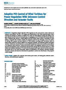
Schulich School of Engineering Department of Mechanical and Manufacturing Engineering
Adaptive Control of Variable-Speed Variable-Pitch Wind Turbines Using RBF Neural Network By: Hamidreza Jafarnejadsani, Dr. Jeff Pieper , and Julian Ehlers October 2012, London, ON EPEC 2012
OVERVIEW 1
• Introduction to Wind Turbine Control System
2
• Wind Turbine Modeling
3
4
• Torque Control Using RBF Neural Network
• Pitch Control Using RBF Neural Network
5
• Results of Simulations Using FAST Software
6
• Future Work: L1-Optimal Control of Wind Turbines EPEC 2012
2
Wind Turbine Control System Outer Loop (slow time response) � Aerodynamics � Mechanical Subsystems (Drive Train and Structure) Inner Loop (fast time response) � Power Generator Unit � Pitch Servo
[Ref:Boukhezzar, B., H. Siguerdidjane, “Nonlinear Control with Wind Estimation of a DFIG Variable Speed Wind Turbine for Power Capture Optimization] 3 EPEC 2012
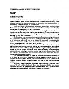
Control Strategy and Objectives � Variable-Speed, Variable-Pitch Control
Ideal power curve [Ref: Wind Turbine Control Systems, Page 51]
� Control Objectives: 1) Energy Capture 2) Power Quality 3) Mechanical Loads EPEC 2012
4
Non-linear Equations of Wind Turbine � Drive-train shaft dynamics:
� Elastic tower fore-aft motion:
� Where: • • • • • • • • •
Ω: Rotor Speed d: Tower top Displacement λ: Tip-Speed Ratio Cp: Power Coefficient Vw: Wind Speed Ta: Aerodynamic Torque: Tel: Generator Torque Fa: Thrust Force M t, Ct, Kt: Equivalent Mass, Damping Ratio, and Stiffness of Tower EPEC 2012
5
Non-linear Equations of Wind Turbine •
λ: Tip-Speed Ratio
•
Ta: Aerodynamic Torque
•
Fa: Thrust Force
•
Cp: Power Coefficient
•
Control Inputs: Generator Torque (Tel) & Pitch Angle (βe) EPEC 2012
6
FAST Wind Turbine Simulation Software � FAST: (Fatigue, Aerodynamics, Structures and Turbulence) is an Aeroelastic Simulator. Developed by NREL(National Renewable Energy Laboratory), Golden, CO � A Variable-Speed Variable-Pitch Wind Turbine: NREL-Offshore-Baseline-5MW (Parameters developed by NREL) Rating Rotor Orientation, Configuration Control Rotor, Hub Diameter
5 MW Upwind, 3 Blades Variable Speed, Variable Pitch 126 m, 3 m
Hub Height Cut-In, Rated, Cut-Out Wind Speed Cut-In, Rated Rotor Speed Rotor Mass
90 m 3 m/s, 11m/s, 25 m/s 6.9 rpm, 12.1 rpm 110,000 kg
Optimal Tip-Speed-Ratio
7.55
Rated Generator Torque
43,100 Nm
Maximum Generator Torque
47,400 Nm
Rated Generator Speed
1174 RPM
EPEC 2012
7
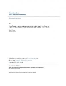
Radial-Basis Function (RBF) Neural Networks � RBF Neural Networks Approximate the Nonlinear Dynamics of Control System � Robust to Uncertainties and Disturbances in the System � Fast Time Response
A two-point radial-basis function [Ref: Stanislaw H Zak, Systems and Control, pg 495] EPEC 2012
8
Torque Control � � � �
At wind speeds lower than rated wind speed Maximum power capture Constant Pitch Angle Equation is in the affine form
� RBF NN Approximator
EPEC 2012
9
Control Design and Updating Rule Using Lyapunov Theory � Tracking error:
� Controller:
� Lyapunov function:
� Robust weight update using e-modification method:
EPEC 2012
10
Pitch Control � � � �
At wind speeds Higher than rated wind speed Limiting the power capture at nominal capacity of wind turbine Constant generator torque Equation is in the non-affine form
EPEC 2012
11
Control Design and Updating Rule Using Lyapunov Theory � Transformation (Inverse Dynamics Method)
� Approximating ideal controller using NN:
� Mean value thorium:
� Lyapunov function:
� Robust weight updating rule : EPEC 2012
12
Wind Speed Profile
EPEC 2012
13
Results (Electrical Output Power)
EPEC 2012
14
Results (Control inputs)
EPEC 2012
15
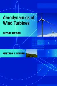
Results of Simulation Using FAST Software for Region I (Maximum Power area) • Wind Inputs: TurbSim-generated 24 x 24 grids of IEC Class A Kaimal-spectrum turbulence • Six turbulence realizations per mean wind speed are simulated. Electrical Power Output 3500
3000
Power (kW)
2500
2000
Neural Network Controller 1500
PI Controller 1000
500
0 0
2
4
6
8
10
12
Average Wind Speed EPEC 2012
16
Results of Simulation Using FAST Software for Region III (Rated Power Area): � Comparing The Performance of Controllers: 1) Gain-Scheduled PI-Control ( Developed by NREL) 2) Proposed Adaptive Neural Network Control
EPEC 2012
17
Results (Electrical Output Power)
EPEC 2012
18
Results (Control input1: Generator Torque)
EPEC 2012
19
Results (Control input2: Pitch Actuation)
EPEC 2012
20
Introduction to L1-Optimal Control � The final purpose of L1-optimal control is to find a controller (K) to stabilize the closed-loop system and minimize the L∞-norm between disturbance input(w) and performance output (z).
Why L1-Optimal Control? � 1) Persistent exogenous disturbances and noises. These inputs obviously have infinite energy(L2-norm). However, they have bounded magnitudes(L∞-norm). • EX: varying wind conditions that face the wind turbine. � 2) Direct time-domain performance specifications • EX: overshoot, bounded magnitude, bounded slope, or actuator saturation
LMI (Linear Matrix Inequality) Approach to L1-Optimal Control � LMI method results in a convex minimization problem subject to LMI constraints EPEC 2012
21
Thank You For Your Attention ??
EPEC 2012
22