1574
IEEE TRANSACTIONS ON COMMUNICATIONS, VOL. 54, NO. 9, SEPTEMBER 2006
Adaptive Demodulation Using Rateless Erasure Codes J. David Brown, Subbarayan Pasupathy, Fellow, IEEE, and Konstantinos N. Plataniotis, Senior Member, IEEE
Abstract—We introduce a rate-adaptive system in which the receiver demodulates only those bits that have a high probability of being correct, treating nondemodulated bits as erasures. Several sets of decision regions, derived using composite hypothesis testing, are proposed for 16-QAM and 16-phase-shift keying, which allow for the simple implementation of this demodulation strategy. We demonstrate that pre-encoding the data with a Raptor code allows for simple reconstruction of the message, regardless of the erasure pattern introduced from the nondemodulated bits. We prove the optimality of the proposed decision regions in selecting the most likely subset of bits from any received symbol in moderate-to-high signal-to-noise ratios, and we analyze the performance of demodulating with these decision regions over an additive white Gaussian noise channel. Also demonstrated is the strong performance of 16-QAM for this application, compared with other power-efficient constellations and the near-optimality of using Gray mapping, even under the proposed alternate sets of decision regions. Index Terms—Adaptive modulation, decision regions, demodulation, Gray mapping, hierarchical modulation, phase-shift keying (PSK) constellations, quadrature amplitude modulation (QAM) constellations, Raptor code.
I. INTRODUCTION ATE-ADAPTIVE systems provide an elegant solution to the problem of transmitting data over a time-varying channel. Two popular rate-adaptive systems are adaptive modulation and incremental redundancy (IR). In an adaptive modulation system, the transmitter dynamically adjusts the modulation level used according to the (presumably) slow variations in the channel, as in [1] and [2]. The modulation scheme used at any instant is chosen such that a target bit-error rate (BER) is maintained for the duration of the transmission—clearly, over poor channel instants, a low order of modulation would be selected, while a higher order of modulation would be used during favorable channel instants. In contrast to adaptive modulation systems, IR schemes (first introduced in [3]) achieve rate adaptation by encoding data packets using a low-rate “mother code” and transmitting subpackets one by one using an automatic repeat request (ARQ) algorithm, until the receiver successfully decodes the original packet. These systems are in contrast to typical nonrate-adaptive systems where the modulation, coding, and power level are fixed
R
Paper approved by A. Anastasopoulos, the Editor for Wireless Communications of the IEEE Communications Society. Manuscript received August 11, 2005; revised December 15, 2005. This work was supported in part by a postgraduate scholarship from the Natural Sciences and Engineering Research Council of Canada (NSERC), and in part by an Industry Canada Fessenden postgraduate scholarship. The authors are with the Department of Electrical and Computer Engineering, University of Toronto, Toronto, ON M5S 3G4, Canada (e-mail: brown@dsp. utoronto.ca;
[email protected];
[email protected]). Digital Object Identifier 10.1109/TCOMM.2006.881236
ahead of time to achieve a desired level of performance; in the case of a time-varying channel, these systems are designed for the worst-case channel conditions with a fixed power margin or coding gain applied in order to ensure acceptable average performance over the entire channel range. Despite the obvious advantages of adaptive modulation and IR, both schemes present some difficulties, as well. Most current adaptive modulation schemes work with the assumption that the transmitter has relatively accurate knowledge of the channel [i.e., to make a modulation choice, the transmitter needs to know the received signal-to-noise ratio (SNR)]. Typically, the transmitter obtains knowledge of the channel state from the receiver by means of a feedback path, which may consume a significant amount of overhead, especially if the channel information changes rapidly relative to the symbol rate. Furthermore, inaccuracies in the estimate of the channel state at the transmitter can lead to degradation in performance (e.g., [4]). IR schemes (specifically type-II hybrid ARQ schemes) avoid the requirement for channel feedback to the transmitter, but require instead a second-layer ARQ protocol scheme to operate. An additional complication of IR is that the decoding procedure is repeated after each subpacket is received to check for successful transmission (essentially wasting resources each time the decoding scheme fails). A final concern is the potentially large buffer in such a scheme, which must be designed for the worst-case scenario and may be severely under-utilized under typical channel conditions. Here, we present a novel adaptive demodulation (ADM) scheme, which preserves the advantageous properties of traditional rate-adaptive schemes, while avoiding some of their pitfalls. Essentially, in the proposed ADM scheme, the transmitter would send a fixed modulated and coded data stream, and the receiver would demodulate the symbols at a nonfixed rate, where the demodulation rate at any instant would be determined by the observed channel state at the receiver. Thus, the receiver would demodulate only those bits which have a high degree of certainty, and would treat as erasures any bits which have an increased chance of being in error. For certain two-dimensional (2-D) signal constellations and symbol mappings, this selective demodulation can be accomplished very easily using a remarkably simple set of decision regions. To send a -bit message using such a system, a particularly straightforward way to do so is to first encode the message using a rateless erasure code, such as a Raptor code [5]. If such a code is used, then to decode, bits (where is the receiver must simply accumulate small and depends on the design of the code), all of which are highly reliable due to our ADM scheme. During a favorable channel instant, the ADM scheme would introduce no erasures, and full-rate communication would be
0090-6778/$20.00 © 2006 IEEE
BROWN et al.: ADAPTIVE DEMODULATION USING RATELESS ERASURE CODES
1575
preserved (note that the rate would be slightly reduced by due to the outer code). Under poor channel conditions, the appropriate decision regions would be chosen such that only those bits most likely to be correct would be collected, thus decreasing the error rate (at the cost of a reduced data rate). This effectively achieves the results of a regular adaptive modulation scheme without requiring any channel-state information feedback to the transmitter. The scheme also overcomes the limitations of IR schemes: a traditional ARQ protocol is not needed, , and the receiver needs to the buffer size is limited to decode only once. The fact that particular bits in a signal constellation have a higher degree of certainty than others has been used previously in the study of codes with unequal error protection [6], [7]. Also of interest are nonuniform phase-shift keying (PSK) and quadrature amplitude modulation (QAM) constellations (sometimes called hierarchical modulation) discussed in, for example, [8] and [9] for the broadcast channel in which certain “base bits” are transmitted with a high probability of being correct, while additional “refinement bits” can be observed only by users in high-SNR regions. These systems focus on ensuring a base bit stream is available to all users (with refinements available when possible); in contrast, our system does not specify any base bits or refinement bits a priori in a symbol, but focuses on demodulating whichever bits are more likely at the receiver. In the system we consider, we do not classify certain bits as more important or higher priority, since under the rateless code construction, all bits are of equal importance. Our system focuses on a rate-adaptive method for complete packet delivery, as opposed to a constant low-rate bit stream with enhancements available for certain users. The remainder of the paper is organized as follows. Section II contains an overview of rateless erasure codes, along with a description of the system model. The question of how to determine the optimal decision regions (for the reduced rates) for a given signal constellation is addressed in detail in Section III, which includes a derivation of the optimal set of adaptive decision regions for Gray-coded 16-QAM and 16-PSK using estimates of the log-likelihood ratio (LLR) of each bit in the modulated symbol. The section also includes an analysis of the BER performance of these decision regions. In Section IV, we discuss the optimality of using the Gray mapping for 16-QAM and 16-PSK in the ADM scheme; we also discuss other signal constellations and their respective performance in the ADM scheme. Results of simulations of the ADM scheme using Gray-coded 16-QAM and precoded with a Raptor code are given in Section V. Finally, Section VI provides a brief summary of the paper and comments on future directions.
The Luby Transform (LT) code, proposed by Luby [10], is an important erasure-correcting code which implements the so-called “digital fountain” concept of erasure correction introduced in [12]. Such a code allows the encoder to produce a potentially limitless number of code symbols from a source packet of symbols. Ideally, a receiver would be able to decode the source packet as soon as it has received any set of (or slightly more than ) code symbols, assuming all received code symbols are correct (as they would be in an erasure-channel setting). These codes can be considered “rateless,” since regardless of the loss pattern of the erasure channel, the transmitter stops generating and sending code symbols as soon as the symbols, and the number of receiver receives any code symbols to be generated is not constrained ahead of time. The Raptor code extends these ideas to reduce encoding and decoding complexity. Although LT and Raptor codes were originally designed for use with erasure channels, their performance over other channels, specifically the binary symmetric channel (BSC) and the additive white Gaussian noise (AWGN) channel, has been considered in [13]. There, it is found that the Raptor code can, in fact, correct errors (with an increase in required as the noise increases), while the LT code exhibits an error floor. The performance of Raptor codes on symmetric channels is further investigated in [14], where it is shown that the degree distributions of the code can be tailored to suit the given channel in order to achieve optimal performance. Of particular interest is that on the erasure channel, there are known to exist so-called universal degree distributions, which provide optimal (capacity-achieving) performance for any loss probability . On the BSC, however, no such universal distributions exist; thus, as the bit-flip probability changes, so too does the optimal degree distribution.
II. BACKGROUND AND SYSTEM MODEL
is the th symbol (and is complex), where is the received pulse shape, is the symbol period, and is the white noise process. is passed through a filter matched to At the receiver, the received pulse shape, , and is sampled at the symbol , where rate to produce the vector , assuming the energy of the received pulse shape is noris a complex noise sample with variance malized to one, and in each dimension. At the same time, an estimator
A. Rateless Erasure Codes Though the focus of this paper is on the decision regions, signal constellations, and symbol mappings involved in implementing an ADM scheme, a brief discussion of the outer code is provided here to facilitate an overall appreciation for the system; further details of rateless erasure codes are provided in Appendix I as well as [5], [10], and [11].
B. System Model Our system is described as follows. To transmit a -bit message , we first encode it using a Raptor code, which produces a continuous bit stream of unspecified length (the code terminates when a single acknowledgment is received). The bit stream is modulated using a standard modulation method (with symbol alphabet ) to produce a symbol stream which is sent over the channel. For the moment, we consider a simple AWGN channel where the noise process has a two-sided power spectral density . At the receiver, the observed signal representing (PSD) of a train of symbols is given by
(1)
1576
IEEE TRANSACTIONS ON COMMUNICATIONS, VOL. 54, NO. 9, SEPTEMBER 2006
We require decision regions that select the most reliable subset of bits in a symbol (or, equivalently, ignore the least reliable subset). Let a -decision region set ( -DRS) be a set of decision regions that recover bits per symbol. Thus, most reliable bits for any a -DRS must determine the . The decision for the value of a particular bit received of (where ), can be formulated as a binary composite hypothesis test, similar to the method used represent the set of in [15]. Let constellation points for which bit is 1, where there are constellation points with a 1 in bit position ; similarly, let be the set of points where bit is 0, constellation points with a 0 in bit and where there are is to position . Thus, our hypothesis testing problem for decide between Fig. 1. Standard 16-QAM constellation with symbols mapped using Gray code. The distance between nearest neighbors is 2c.
is used to determine the received SNR over each symbol (or each block of symbols). Of course, in a true AWGN channel, the noise variance would be fixed, and continuously performing estimates would be redundant; the estimator truly belongs in a time-varying channel implementation. Based on the estimate of the received SNR and the desired maximum allowable BER, the receiver chooses which set of decision regions it will use to determine the constituent bits in each symbol (and which bit positions, if any, will be ignored). Using the appropriate decision regions, bits are accumulated in bits. Once the buffer is full, a buffer until we have the packet is decoded (using belief propagation (BP) here) to produce the original bits, . III. ADAPTIVE DECISION REGIONS FOR 16-QAM AND 16-PSK WITH GRAY MAPPING A. Gray-Mapped 16-QAM We consider first an ADM system that uses a 16-QAM signal constellation where the bits are mapped to the symbols using Gray mapping, as in Fig. 1. We would like to modify the standard decision regions to provide alternate sets of regions which specify, for a given , a subset of the four bits in the symbol that excludes the least reliable bit(s). The construction of such decision regions is not necessarily intuitively obvious. For instance, initially, one might be tempted to recover two bits per symbol by simply drawing decision region boundaries along the real and imaginary axes and decoding the two bits in common in each quadrant (e.g., a received vector in the upper right quadrant ). This method works well in nonuniwould be decoded as form QAM constellations, but not so well here, as we will see. Immediately, we notice that the error rate we would experience on the two recovered bits will not be dramatically smaller than the regular 16-QAM error rate, since the signal points next to the axes are still a distance of (in at least one direction) from a boundary, where nearest neighbors are separated by a distance of . Thus, a systematic method to construct decision regions is required.
(2) If we assume that it is equally likely that a 0 or 1 was trans), then the opmitted in position (so that timal detector for simply evaluates the sign of the LLR given by
(3)
where to obtain the second line requires the additional assumption that all symbols are equally likely. To obtain the most reliable bits in , we then must choose the strongest hypotheses among all , or equivalently, we must identify the LLRs with the largest magnitudes. The magnitudes of the LLRs indicate the most reliable bit positions for a given , and the signs of the LLRs indicate the most likely values of the bits in those positions. for Analytically comparing the magnitudes of is not an easy task. Instead, we develop a good approximation for (3) to simplify our analysis. For high SNR, the sum of exponentials in the numerator and denominator of (3) are well represented by a single dominant exponential term. that maximizes Now the is the one that minimizes the Euclidean distance . Similarly, the closest to (in Euclidean distance) produces the dominant exponential term in the denominator. Thus, and represent the closest symbol points to from letting and , respectively, we can write (4) and represent the energy of symbol points where and . results in the following apCareful evaluation of (4) over proximations for the magnitude of the LLRs (assuming once
BROWN et al.: ADAPTIVE DEMODULATION USING RATELESS ERASURE CODES
1577
again that the energy of the shaping pulse is normalized to 1 and that is the distance between nearest neighbors in Fig. 1):
(5) (6) (7) (8)
where represents the real part of , and represents its imaginary part. These approximations are very close to the true LLRs for as low as 3 dB high-to-moderate SNR values. In fact, for is the average energy per bit), we find that the approx(where imation is very good when we compare (5)–(8) to a numerical evaluation of (3) over a wide range of .1 Using the approximations for the magnitudes of the LLRs of each bit, it is a relatively simple (although somewhat laborious) task to rank the magnitudes from largest to smallest for all possible values of . Using these rankings, one can then create decision regions to choose the most probable bits for any received , with the boundaries of the decision regions given by simple analytical linear equations. It turns out that the -DRSs we obtain for Gray-mapped 16-QAM using this method (based on the approximate LLRs) are independent of (assuming it is at least moderate to large), and are remarkably simple to implement. In Fig. 2, we show the 3-DRS and 2-DRS for Gray-mapped 16-QAM; the symmetry and simplicity of both DRSs is immediately apparent. For the 2-DRS, the dotted lines in Fig. 2 indicate the decision regions obtained using the approximate LLRs, while the solid lines indicate a simplification that produces a checkerboard pattern for the decision regions. The simplification proves to be an attractive alternative, since its performance is nearly identical to the set of decision regions specified by the dotted lines, but is simpler to implement. The near-equivalent performance results from the fact that the sloped boundaries of the 2-DRS do not play a major role in calculations for the dominant term of the BER expression. As the decision regions shown in Fig. 2 were derived using approximate LLRs, we would expect them to be valid for moderate-to-large SNR. To verify that this is indeed true, we evaluated the exact LLRs of (3) for each bit (using MATLAB2) for values and generated contour plots of the apa 2-D array of propriate DRSs over a range of SNR values. We found that 1Also of interest are some approximations of the LLRs of each bit in 16-QAM proposed in [16] for use in decoding turbo codes; they achieve similar results for ln(3 (r )) and ln(3 (r )), but their approximations for ln(3 (r )) and ln(3 (r )) are less accurate for larger r and r . Additionally, in a recent paper [17], Simon and Annavajjala developed a set of exact expressions for the LLRs; these, however, are complicated nonlinear expressions not suited for the analysis we propose below. 2The MathWorks Inc., 2002.
Fig. 2. 16-QAM DRSs to recover 3 and 2 bits per symbol. For the 2-DRS, the solid lines indicate a modified (simpler) DRS to recover 2 bits, with nearly identical performance to the optimum DRS specified by the dotted lines.
the decision regions derived using the approximation correspond precisely to the ones produced by our simulation for as low as 0 dB. Thus, for practical SNR values, the approximate decision regions are certainly valid (and are much simpler to implement than numerically evaluating (3) for every given received ). B. Gray-Mapped 16-PSK We choose Gray-mapped 16-PSK (Fig. 3) as another candidate on which we apply our analysis to determine its reduced DRSs. Though not as popular as 16-QAM, the symmetry of 16-PSK makes it conducive to analysis, and provides a good
1578
IEEE TRANSACTIONS ON COMMUNICATIONS, VOL. 54, NO. 9, SEPTEMBER 2006
Fig. 3. Gray-mapped 16-PSK constellation with radius c.
first step in comparing constellations and their behavior under ADM. Determining the -DRSs for Gray-mapped 16-PSK once again requires evaluating (3) for each bit over all , and then and choosing the largest LLRs. Of course, the sets are modified appropriately to reflect the 16-PSK constellation points. As before, it is possible to approximate the LLRs of the bits in 16-PSK at high SNR by choosing the dominant term in the sum of exponentials. Since the energy of all constellation points is constant for 16-PSK, the approximation resembles (4) without the energy terms
(9) where, once again, and represent the closest symbol from and , respectively. points to It turns out that (9) is a little more complicated to evaluate and making use of than (4). Writing in polar form as some trigonometric identities, we can show that (10) where is the angle of the symbol closest to (i.e., is the is the angle of ) and is the distance of angle of , and each symbol point from the origin. Armed with (10), it is now possible (although computationally tedious) to analytically determine the -DRSs for 16-PSK. By examining (10), it is obvious that our decision regions will not be dependent upon SNR, since all LLRs share a common . In fact, it turns out that the boundaries befactor of tween decision regions will comprise pie-shaped sections, exactly as in regular 16-PSK. Additionally, due to the symmetry of the constellation, the boundaries for 3-DRS and 2-DRS always appear on or exactly in between two signal points. The complete 3-DRS and 2-DRS for 16-PSK are shown in Fig. 4. Similar to the 16-QAM case, these DRSs are robust across a large range of SNRs. Indeed, when the exact LLRs of (3) are
Fig. 4. 16-PSK DRSs to recover 3 and 2 bits per symbol.
used to numerically compute the DRSs over a 2-D array of we find that our approximation is valid, at least down to as low as 0 dB.
,
C. Bit-Error Probability To complete our analysis of the DRSs for Gray-mapped 16-QAM and 16-PSK, we would like to compute the BER for 3-DRS and 2-DRS. The computation is similar to the method followed in [18, pp. 187-194] for computing the BER of -QAM and -PSK using standard decision regions. The BER curves we generate indicate the probability of error of the demodulated bits, not of the erasures (note that the erasures do not result in errors, as their positions are known). We begin by computing the probability of symbol error for the 3-DRS of 16-QAM (decision regions shown in Fig. 2). We say that a “symbol error” occurs if any of the three bits on which we make a decision are incorrect. This is unlike standard demodulation, in that we are not making a decision on precisely which symbol was transmitted; instead, we are choosing the three most likely bits (which, in this case, amounts to making a decision
BROWN et al.: ADAPTIVE DEMODULATION USING RATELESS ERASURE CODES
1579
that the transmitted symbol was a member of a set of the two most likely symbols). To compute the symbol error, we begin by considering the , , four inner points of the constellation (located at , ); by symmetry, all of these points have the same symbol error, and we need consider only one of them, e.g., (see Fig. 1), as having been transmitted. Inspection of the 3-DRS in Fig. 2 shows that if an inner point is transmitted, the decision on three bits will be correct if lands in any of the four decision regions surrounding that point. As the noise is assumed and as independent to be circularly symmetric, we define Gaussian random variables with variance , where is the noise along the rad component, and is the noise rad component. Thus, we can write along the correct
Fig. 5. BER performance for 16-QAM, 3-DRS, 2-DRS, and 16-PSK, 3-DRS, 2-DRS.
It is then straightforward to show that error
where is the energy per bit, and is the area under the tail of the Gaussian distribution; specifically, . It is interesting to note here that for an error to occur, the noise must have a value , in contrast to regular 16-QAM demodulation, larger than where the noise must only exceed ; thus, we indeed observe an improvement in the distance properties of these decision regions. In computing the above, we must be careful to remember that since each symbol now only conveys three bits, where (as opposed to regular then ). 16-QAM, where The symbol error for the eight points on the sides and the four points in the corners of the 16-QAM constellation can be computed using a similar technique to the above. As some of the boundaries for these points are not rectangular, a simple estimation technique in [18, p. 190] is used for these cases. Putting all this together, we find that the symbol error for the 3-DRS is given by
(11) This analysis is repeated for the simplified (i.e., solid-line boundaries) 2-DRS case of Fig. 2. Here we find that the noise must exceed in order to cause an error, thus further improving our distance properties; this time, however, we must use in our calculations. Since all decision boundaries in this case are rectangular, our calculation is exact, and we find (12)
It turns out that for this constellation and mapping (for both 3-DRS and 2-DRS) when symbol errors do occur, the most likely symbol errors are ones which result in only one bit error (since the nearest surrounding decision regions differ by only one bit, and possibly one erasure position). Thus, we can approximate the bit error for 3-DRS and 2-DRS using and . These estimates for BER are very tight, as can be seen in Fig. 5, where the estimates are plotted alongside simulated results for 3-DRS and 2-DRS. The error rate for regular 16-QAM shown in the figure is
as per [18, p. 193]. For 3-DRS, we see a gain of 1.76 dB over 16-QAM, and for 2-DRS, we see a gain of 3 dB. In fact, these gains are slightly misleading. If the intent of our ADM system is for the transmitter to always maintain the same format, then the transmitter would be constant. In this would keep its power fixed, hence case, were our receiver to switch from demodulating 16-QAM to demodulating using 3-DRS, our BER would be determined value of instead using the 3-DRS curve, and using an . Thus, when we plot our BER versus as in Fig. 6, of we find that the curves are spaced further apart than in Fig. 5, indicating a wider range of operation. Finally, we examine the BER for the reduced DRSs for 16-PSK. These results are derived following similar steps to the derivation of the BER for regular 16-PSK as in [18, p. 190], and are stated below (13)
(14)
(15)
1580
IEEE TRANSACTIONS ON COMMUNICATIONS, VOL. 54, NO. 9, SEPTEMBER 2006
Fig. 6. BER performance for 16-QAM, 3-DRS, 2-DRS as a function of E =N .
These curves are plotted in Fig. 5. We see that, as one might expect, the performance of 16-PSK is inferior to 16-QAM in the reduced-decision-region case. We note that for the 16-PSK system, the spacing between the curves is larger (with a gain of 4.7 dB for the 3-DRS and a gain of 6.1 dB for the 2-DRS) than for 16-QAM. IV. ADAPTIVE DECISION REGIONS FOR ALTERNATE MAPPINGS AND CONSTELLATIONS The shape of adaptive decision regions and their BER performance are determined by two factors: the mapping of bits to symbols and the choice of constellation. In this section, we will examine the choice of constellation and mapping and how this affects both the shape and BER performance of a set of decision regions. A. Mapping Choice In Section III, we derived the BER of the adaptive decision regions for Gray-mapped 16-QAM and 16-PSK. Here we present some heuristic arguments, indicating that Gray mapping is indeed an optimal or near-optimal choice for these constellations in the ADM scheme. The arguments presented assume we are operating at moderate-to-high SNR. We consider first an arbitrary mapping for 16-QAM; we wish to determine an approximation for the best achievable BER when we recover three bits per symbol. Let us consider point , one of the four inner points in the 16-QAM constellation with . There are exactly four symbols which a labeling of are a Hamming distance of one from , specifically, , , , and , where represents the binary opposite of . Now, has four nearest neighbors of disand four diagonal neighbors of distance . Thus, tance at least four of the neighbors of (either nearest neighbors or diagonal neighbors) must be labeled with symbols having Hamming distance greater than one. Now, if any neighbor of is labeled with a symbol having Hamming distance greater than one, then a boundary would be required between and this neighbor, since the two symbol points would not share
three bits in common (and thus, could not mutually agree on three bits). To minimize our BER (for ), we need to ensure that the boundaries are as far as possible from ; thus, we assign to the nearest neighbors the symbols with Hamming to be distance of one. The diagonal neighbors will cause away. An error surrounded by four boundaries, each in either of two dimensions, occurs if the noise exceeds resulting in a symbol-error probability (SEP) of approximately best SE,3DRS inner point . We consider next the four corner points. These each have two nearest neighbors and one diagonal neighbor. For the reasons discussed above, we let the nearest neighbors be labeled with symbols of Hamming distance one from the corner point. For the diagonal neighbor, we could label it with a symbol having Hamming distance one (since there are four of these available); however, when we do this, we find that the diagonal neighbor and the two nearest neighbors are now separated by a Hamming distance of two, which will significantly reduce the overall performance of the constellation. A better result is obtained if we allow the diagonal neighbor to be a distance of two from the corner point and one from the nearest neighbors. This results in away and gives a SEP of a single boundary a distance of . approximately best SE,3DRS corner point Similar arguments can be used to show that under optimal mapping, the side points have SEP of best SE,3DRS side point . Using this result and the results above, we can say that for an arbitrary mapping (for recovering three bits per symbol), the best achievable SEP . Using is approximately best SE,3DRS (for 3-DRS), we can (11) and write the SEP for the 3-DRS of Gray coded 16-QAM as
SE,3DRS Comparing this with the approximation for best achievable symbol error, we conclude that Gray mapping provides one possible configuration of near-optimal mapping for recovering three bits per symbol in 16-QAM at moderate-to-high SNR. An argument similar to the one above can also be used to show that Gray mapping is a near-optimal mapping to recover three bits per symbol in 16-PSK. Appendix II contains additional arguments regarding the best symbol mapping for 16-QAM and 16-PSK when recovering two bits per symbol; it turns out that Gray mapping is once again near-optimal. B. Constellation Choice In examining constellation choice, we study several popular constellations. We do not prove that any one constellation is “optimum,” but instead evaluate the relative simplicity (or complexity) of the reduced decision regions, as compared with QAM and PSK, and compare the respective BER performance. We choose to examine three additional 16-ary constellations: (1,5,10) ring, (5,11) ring, and optimum hexagonal. These constellations, shown in Fig. 7, are chosen since they (along with 16-QAM) are among the most power-efficient in AWGN, as indicated in [19]. The ring ratios are chosen to be
BROWN et al.: ADAPTIVE DEMODULATION USING RATELESS ERASURE CODES
1581
Fig. 9. BER performance for optimum hexagonal and (8,8) ring for recovering four, three, and two bits.
Fig. 7. Alternate power-efficient constellations. (a) (1,5,10) ring. (b) (5,11) ring. (c) Optimum hexagonal. (d) (8,8) ring.
Fig. 8. BER performance for (1,5,10) ring and (5,11) ring for recovering four, three, and two bits.
for (1,5,10) and for (5,11) to achieve optimal BER performance, as shown in [20]. Because the three additional constellations under consideration do not possess the same degree of symmetry as 16-QAM and 16-PSK, analytically determining the DRSs is not feasible. Instead, to determine the shape of the reduced decision regions for these constellations, we numerically evaluated (3) over a values using MATLAB. Our simula2-D array of possible tion showed that neither the 3-DRS nor the 2-DRS is particularly simple or easy to implement, as both contain amorphous, nonsymmetrical, nonlinear boundaries (figures not shown). The BER performance of these constellations under the reduced decision regions is shown in Figs. 8 and 9. The performance curves for all three constellations reveal an initially sur-
prising result: at high SNR, we find that the BER for every constellation using the 3-DRS is actually worse than the BER of the equivalent system when demodulating all four bits. In fact, for the (1,5,10) ring and optimum hexagonal constellations, even the 2-DRS performs worse than the standard system at high SNR. To explain the poor performance of the 3-DRS for all three constellations, we observe that for each of these constellations, we can identify pairs of nearest neighbors with Hamming distance of two or greater (e.g., for the (1,5,10) ring, we have 0100 neighboring 1001, for optimum hexagonal, we have 1110 neighboring 1011, and for the (5,11) ring, we have 1111 neighboring 1100). Since these neighboring points do not share three bits in common, any implementation of a 3-DRS (recovering the three most likely bits) must have a boundary between these nearest neighbors. Consequently, the distance properties of the constellation (for those particular points) are not improved by using the 3-DRS, and this effect will tend to dominate the error at high SNR. This suggests that at high SNR, the 3-DRS symbol error expressed as a function of will share a dominant term (up to a scaling factor) with the symbol error of the standard demodulator, since both will have decision boundaries between some nearest-neighbor pairs. When we consider bit error , we use for 3-DRS (instead as a function of when demodulating four bits), which results in of 3-DRS actually performing worse than the standard demodula). Since the gain experienced tion case (as a function of by neglecting the least probable bit is minimal (due to the deficient 3-DRS distance properties), this gain is outweighed by the effective additional power allocated to each bit when we demodulate fewer than four bits per symbol. If we were to plot , we would observe that 3-DRS does inthe BER versus deed offer an improvement in performance for a fixed carrier strength, although only a slight one. For the (1,5,10) ring and optimum hexagonal constellations, the poor performance of the 2-DRS is explained in a similar fashion. For these constellations, we note that there exist certain pairs of neighboring points that have a Hamming distance of three (e.g., 0100 and 1001 for the (1,5,10) ring, and 1111 and
1582
0100 for optimum hexagonal). As explained above for 3-DRS, this will result in deficient distance properties for the 2-DRS, since the 2-DRS will require a boundary between these nearest neighbors. We note that the (5,11) ring constellation does not have any nearest-neighbor pairs having a Hamming distance of three; this results in a marked improvement of the 2-DRS for the (5,11) ring. As a final note, we observe that none of the three additional constellations considered performs nearly as well as 16-QAM in the reduced-decision-region case. Motivated by some of the deficiencies observed in the ring and optimum hexagonal constellations, we now propose two properties of “good” constellations to use with reduced decision regions. Property 1: No symbol point in an -ary constellation should have more than minimum-distance-nearest-neighbors (so in our 16-ary constellations, no symbol point should have more than four nearest neighbors). , Proof: For any -ary symbol, there exists at most other -ary symbols of Hamming distance one from (since to achieve a Hamming distance of one, we can flip at most one bit at a time in , and has bits). Thus, any symbol with more than minimum-distance-nearest-neighbors must have a nearest neighbor -DRS with Hamming distance two or greater. The most likely bits in a symbol; if there recovers the exists a symbol with a nearest neighbor having Hamming -DRS must have distance of two or more, then the a boundary between these neighbors, since they do not share bits in common. To avoid errors on such a symbol point, the noise on that received symbol point (in at least one (where dimension) would need to be smaller than is the distance between nearest neighbors); at high SNR, this -DRS, degenerate case will dominate the error of the resulting in no significant gains in performance over the standard case. Property 2: No three points in an -ary constellation should be mutual-minimum-distance-nearest-neighbors3 (i.e., the constellation should not contain equilateral triangles). Proof: Any set of three mutual-minimum-distancenearest-neighbors will contain at least one point which is a Hamming distance of two or greater from at least one other -ary symbol point. This can be seen by considering the ; a second symbol has Hamming distance of one from if and only if a single bit of is flipped (call this bit ). A third symbol of Hamming distance one from can be constructed by flipping of (where ). The Hamming distance between and cannot be one, since they differ in both and . For the same reasons discussed in the proof of Property 1, if we have nearest neighbors differing by a Hamming distance of two (or greater), the -DRS will have a boundary between these neighbors, resulting in no significant gain in distance properties and -DRS performance. 3For three points to be mutual-minimum-distance-nearest-neighbors, we mean that these points are configured such that the distance between each point and the other two points is d .
IEEE TRANSACTIONS ON COMMUNICATIONS, VOL. 54, NO. 9, SEPTEMBER 2006
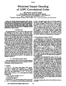
When we consider the (1,5,10) ring, the (5,11) ring, and the optimum hexagonal constellations in light of these properties, we observe that each one of them violates one or both of the properties above. In fact, these properties allow us to eliminate other candidate constellations by inspection. The dense packing of the power-efficient constellations results in no significant additional distance properties when we consider reduced decision regions. Thus, we see that 16-QAM outperforms these constellations in the 3-DRS and 2-DRS cases (and note that 16-QAM does not violate either property). Bearing in mind the two properties above, we consider a final constellation: the (8,8) ring (see Fig. 7) with a ring ratio of 1.765 (chosen to make the distance between the inner and outer rings equal to the distance between points on the inner ring). Though the (8,8) ring does not perform particularly well when recovering four bits per symbol, we observe the interesting property that the performance of 3-DRS and 2-DRS are nearly equal to the performance of 3-DRS and 2-DRS for 16-QAM, as the BER curves in Fig. 9 show. In addition, the 3-DRS and 2-DRS for the (8,8) ring (not shown) are symmetrical and simpler to implement than the 3-DRS and 2-DRS for optimum hexagonal, (5,11) ring, and (1,5,10) ring. We conclude this section with the comment that Graymapped 16-QAM appears to be a very attractive candidate for use in an ADM system. The constellation provides reduced decision regions that are very simple to implement, and which have significantly improved performance, compared with the considered alternatives. 16-PSK also provides simple regions and, although its performance is worse than 16-QAM, its simplicity and constant signal envelope make it attractive, as well. V. NUMERICAL RESULTS Finally, we wish to simulate the performance of the entire system. Based on our results in Sections III and IV, we chose Gray-mapped 16-QAM for our system with the appropriate decision regions as given in Fig. 2. In choosing the code, we used a Raptor code with degree distribution
, and . The degree distribution is one proposed in [5] (for the erasure channel), which was shown to correct errors over a BSC in [13]. The outer code used was a rate-0.95 right regular low-density parity-check (LDPC) code, as described in [11]. It must be noted that in practice, one can design a Raptor code degree distribution (using a linear programming technique) optimized for the error pattern one might expect from the channel, though this is beyond the scope of this paper. Decoding was accomplished using the standard BP algorithm [21] for sparse-graph codes, which was used in [13] and [14] to successfully decode Raptor codes containing transmission errors. Demodulated bits (that were not erased by the reduced decision regions) were each assigned the same likelihood (as if they had emerged from a BSC), in order to provide a reasonable starting point for the decoder after the hard-decision demodulation.
BROWN et al.: ADAPTIVE DEMODULATION USING RATELESS ERASURE CODES
1583
BER as the BPSK system. A simple (and nonoptimal) way of choosing the regions of operation for the ADM system or better) is to determine the (for operation at a BER of instantaneous received SNR (per bit) required for each DRS . Reading off of Fig. 10, we see that we to have BER dB for 2-DRS, dB for need dB for all four bits. This allows 3-DRS, and us to calculate the required instantaneous received SNR per 8.02 dB, 10.57 dB, and symbol, leading to 13.57 dB, where , and are the switching thresholds for 2-DRS, 3-DRS, and full 16-QAM, respectively. Using these (nonoptimal) switching thresholds, the throughput of the ADM system is calculated to be
Fig. 10. Simulation results of Gray-mapped 16-QAM encoded with a Raptor code over an AWGN channel.
The simulation shows the performance of Raptor-encoded 16-QAM using standard decision regions, 16-QAM using 3-DRS, and 16-QAM using 2-DRS. The results of the simulation are shown in Fig. 10. Initially, the primary reason to use a rateless erasure code for the system was that it would allow recovery of the message even when an unspecified number of bits were dropped (due to our reduced decision regions). As can be seen from Fig. 10, however, an additional benefit is that it also provides a significant coding gain. When examining Fig. 10, one must again re, member that were we to plot the performance against we would observe an even greater separation between the curves shown, as discussed in Section III. Additionally, were the code optimized for our particular application, we would expect to achieve greater coding gains than the ones shown here. The simulation results show that using reduced decision regions in concert with a rateless erasure code allows for a feasible implementation of a rate-adaptive system. To implement an ADM system in practice, we could use a set of BER curves such as those in Fig. 10 to determine which set of decision regions the receiver should use to achieve a certain level of performance for any given received SNR. Of interest is the throughput of the ADM system compared with a fixed-rate system. We provide a simple (nonoptimized) example to show the power of ADM. We consider a memoryless Rayleigh fading channel where the instantaneous , where received SNR of each symbol is given by is Rayleigh-distributed with probability density function , with . The (pdf) ; instantaneous SNR per symbol is defined as it is chi-square distributed with two degrees of freedom (due to the ). We define the average received SNR per symbol as . Consider a fixed-rate binary (B)PSK system (that achieves a throughput of 1 bit per symbol). The BER of BPSK over a as per [18, p. Rayleigh fading channel is given by , we need dB. 542]. So to achieve a BER of Now, consider an ADM system operating over the same dB, and at the same Rayleigh fading channel with
bits per symbol, where , and the leading term before the integral represents the reduction in rate . due to the outer LDPC code and the Raptor code with Clearly, even for this nonoptimal example, the ADM system results in a large increase in throughput over the fixed-rate scheme. VI. CONCLUSION We have introduced a novel rate-adaptive system that uses adaptive decision regions at the receiver and a rateless erasure code. The importance of our system is that it avoids some of the problems inherent in adaptive modulation or IR systems (channel feedback, large buffers, or multiple decodings). By developing simple estimates for the LLR of each bit in Gray-mapped 16-QAM and 16-PSK, we showed that their optimum adaptive decision regions have a simple shape, and are robust over a large range of SNRs. To demonstrate the gain in performance offered by the reduced decision regions, we developed tight estimates of the BER for these regions for 16-QAM and 16-PSK. We argued as well that Gray mapping is among the optimal or near-optimal mappings to use to achieve good performance under reduced decision regions for both 16-QAM and 16-PSK. Additionally, we considered three competing powerefficient constellations, and showed that 16-QAM is preferable to these for our application. Finally, we presented simulation results of the performance of the reduced decision regions of Gray-mapped 16-QAM precoded with a rateless erasure code to demonstrate the feasibility of the system. We are currently working to extend the results to encompass fading channels and to optimize the Raptor code for our application. APPENDIX I LT AND RAPTOR CODES An LT code takes a set of input symbols and can generate a limitless stream of output symbols using the following three steps. 1) Randomly choose the degree of the output symbol according to a predetermined distribution.
1584
IEEE TRANSACTIONS ON COMMUNICATIONS, VOL. 54, NO. 9, SEPTEMBER 2006
2) Select of the input data symbols at random using a uniform distribution. 3) The output symbol is the XOR of the input data symbols selected in Step 2. This can be repeated as many times as is necessary to produce a sufficient number of output symbols. To decode an LT code, the receiver waits until it has accumucode symbols and then constructs a (sparse) lated observed output code symbols on bipartite graph, with the one side and the unknown source symbols on the other. A BP algorithm is then applied to the graph to recover the unknown source symbols. In the case of an erasure channel, the BP algorithm simplifies considerably. Of note is that the receiver needs to know the randomly generated degree sequence in order to construct the graph; methods to ensure this are discussed in [10]. A single acknowledgment is sent once the required number of symbols are collected and decoded (for large , this represents negligible overhead). The performance and ultimate success or failure of the code depends upon the selection of the degree distribution (used in Step 1 of the code generation). For LT codes, the degree distribution selected is the robust Soliton distribution, derived in [10]. The focus of the derivation is to ensure that the code will decode to completion with high probability, while at the same time ensuring that the average degree is small and the graph remains sparse. Raptor codes were introduced in [5] to improve on the encoding and decoding complexity of LT codes. A Raptor code can be implemented using a two-step encoding process, whereby a message is first precoded using a standard error-correcting code, and then is further encoded using an LT code (with a potentially modified degree distribution). Shokrollahi shows in [5] that more flexibility is gained by reducing the requirement of the LT code to recover all of the source symbols. In fact, from any received code symbols, it is possible to recover a fixed fraction of the source symbols from the LT code using a modified degree distribution which has fixed average degree (i.e., the degree is independent of , unlike an LT code which uses the robust Soliton distribution). The precode for a Raptor code is chosen in such a manner as to allow recovery of the fraction of erasures remaining after the LT code is decoded. Since the degree distribution is independent of , it allows for linear time encoding and decoding (assuming judicious choice of the precode). Maymounkov independently proposed the idea of using a two-step coding process to reduce the coding complexity and called the resulting codes online codes in [11].
shared two bits in common, it could be considered optimal (or near-optimal) from the point of view that the four most likely symbols (for any point received in the square) all agree on two bits. Thus the square defined by these symbol points would comprise a decision region for two bits. If the mapping of the entire constellation were chosen using this method, then each by square would comprise a decision region uniquely identifying two bits; no two decision regions would identify the same two bits. This leads to a DRS similar to the simplified (i.e., solid-line) one proposed for Gray mapping in Fig. 2. In in either of two dimensions, this case, if the noise exceeds an error occurs. Though this argument is heuristic, it strongly suggests that Gray mapping is one possible configuration to achieve optimal (or near-optimal) mapping to recover two bits per symbol at moderate-to-high SNR. Finally, we want to consider the best mapping to use to recover two bits per symbol from 16-PSK. The following lemma will be useful in our discussion. Lemma 1: Consider a 16-ary constellation where each symbol represents four bits, and let us construct decision regions such that each region specifies two bits per symbol (i.e., a 2-DRS). Then, a maximum of two symbol points can simultaneously satisfy both sides of a boundary between regions. Proof: Let be a boundary between two regions. Consider , and on the the case where the region on one side of is . In this case, clearly only one point can satother side is . Consider a second case, where the isfy both regions: region on one side of is , and on the other side is . and Here, only two points can satisfy both regions: . Finally, consider a third case, where we have on one side and on the other. In this case, no point can satisfy both regions. All other cases can readily be seen to conform to these examples, and our proof is complete. Now let us consider a particular boundary somewhere bein the 16-PSK constellatween consecutive points and tion. From Lemma 1, a maximum of two points can satisfy both sides of the boundary . To achieve the best distance properties, satisfy both sides of the boundary. Now, let points and and (i.e., points and the points on either side of ) will not satisfy both sides of . Thus, an error will occur if noise causes either one of them to fall on the wrong side of . To minimize the probability of error, then, we let fall in and . Thus, the “best case” error the middle between boundary is found at an angular distance of rad, which is precisely the boundaries given by Gray coding.
APPENDIX II DISCUSSION OF OPTIMAL MAPPING FOR 2-DRS
The authors would like to thank F. Kschischang for his insightful comments regarding this work. As well, the authors wish to thank the anonymous reviewers for their helpful suggestions.
We consider the best mapping to use with 16-QAM when recovering two bits per symbol. Suppose a point is received (symbol plus noise) that falls somewhere in the square defined , and (see Fig. 1). The transmitted by the points symbol most likely corresponds to one of the four symbols nearest the received point, i.e., the corners of the square. Now, it is possible to show that a maximum of four symbols can share the same two bit values and positions in common. , and Thus, if a mapping were chosen such that
ACKNOWLEDGMENT
REFERENCES [1] W. T. Webb and R. Steele, “Variable rate QAM for mobile radio,” IEEE Trans. Commun., vol. 43, no. 7, pp. 2223–2230, Jul. 1995. [2] A. J. Goldsmith and S. Chua, “Variable-rate variable-power MQAM for fading channels,” IEEE Trans. Commun., vol. 45, no. 10, pp. 1218–1230, Oct. 1997. [3] J. J. Metzner, “An improved broadcast retransmission protocol,” IEEE Trans. Commun., vol. COM-32, no. 6, pp. 679–683, Jun. 1984.
BROWN et al.: ADAPTIVE DEMODULATION USING RATELESS ERASURE CODES
[4] J. F. Paris, C. Aguayo-Torres, and J. T. Entrambasaguas, “Impact of channel estimation error on adaptive modulation performance in flat fading,” IEEE Trans. Commun., vol. 52, no. 5, pp. 716–720, May 2004. [5] A. Shokrollahi, Raptor Codes 2003 [Online]. Available: http://www.cs. huji.ac.il/labs/danss/p2p/resources/raptor.pdf [6] L. F. Wei, “Coded modulation with unequal error protection,” IEEE Trans. Commun., vol. 41, no. 10, pp. 1439–1449, Oct. 1993. [7] A. R. Calderbank and N. Seshadri, “Multilevel codes for unequal error protection,” IEEE Trans. Inf. Theory, vol. 39, no. 7, pp. 1234–1248, Jul. 1993. [8] M. B. Pursley and J. M. Shea, “Nonuniform phase-shift-key modulation for multimedia and multicast transmission in mobile wireless networks,” IEEE J. Sel. Areas Commun., vol. 17, no. 5, pp. 774–783, May 1999. [9] P. K. Vitthaladevuni and M. S. Alouini, “A recursive algorithm for the exact BER computation of generalized hierarchical QAM constellations,” IEEE Trans. Inf. Theory, vol. 49, no. 1, pp. 297–307, Jan. 2003. [10] M. Luby, “LT codes,” in Proc. 43rd Symp. Found. Comput. Sci., Vancouver, BC, Canada, Nov. 2002, pp. 271–282. [11] P. Maymounkov, Online Codes 2002 [Online]. Available: http://www. scs.cs.nyu.edu/~petar/oncodes.pdf [12] J. W. Byers, M. Luby, and M. Mitzenmacher, “A digital fountain approach to asynchronous reliable multicast,” IEEE J. Sel. Areas Commun., vol. 20, no. 10, pp. 1528–1540, Oct. 2002. [13] R. Palanki and J. S. Yedidia, “Rateless codes on noisy channels,” in Proc. ISIT, Chicago, IL, Jul. 2004, p. 37. [14] O. Etesami, M. Molkaraie, and A. Shokrollahi, “Raptor codes on symmetric channels,” in Proc. ISIT, Chicago, IL, Jul. 2004, p. 39. [15] P. A. Galko and S. Pasupathy, “Optimization of linear receivers for data communication signals,” IEEE Trans. Inf. Theory, vol. 34, no. 1, pp. 79–92, Jan. 1988. [16] S. LeGoff, A. Glavieux, and C. Berrou, “Turbo-codes and high spectral efficiency modulation,” in Proc. IEEE ICC, New Orleans, LA, May 1994, pp. 645–649. [17] M. K. Simon and R. Annavajjala, “On the optimality of bit detection of certain digital modulations,” IEEE Trans. Commun., vol. 53, no. 2, pp. 299–307, Feb. 2005. [18] J. R. Barry, E. A. Lee, and D. G. Messerschmitt, Digital Communication, 3rd ed. Norwell, MA: Kluwer, 2004. [19] S. Y. LeGoff, “Signal constellations for bit-interleaved coded modulation,” IEEE Trans. Inf. Theory, vol. 49, no. 1, pp. 307–313, Jan. 2003. [20] X. Dong, N. C. Beaulieu, and P. H. Wittke, “Signaling constellations for fading channels,” IEEE Trans. Commun., vol. 47, no. 5, pp. 703–714, May 1999. [21] F. R. Kschischang, B. J. Frey, and H.-A. Loeliger, “Factor graphs and the sum-product algorithm,” IEEE Trans. Inf. Theory, vol. 47, no. 2, pp. 498–518, Feb. 2001.
J. David Brown was born in Ottawa, ON, Canada, in 1977. He received the B.Sc.(Eng.) degree in electrical and computer engineering in 2000, and the M.Sc.(Eng.) degree in 2002, both from Queen’s University in Kingston, ON, Canada. He is currently working toward the Ph.D. degree in electrical and computer engineering at the University of Toronto, Toronto, ON, Canada. From 2002 to 2004, he was an Electrical Engineer with General Motors and has also worked at Nortel Networks and Newbridge Networks. His current re-
1585
search interests are in the general field of digital communications, rate-adaptive systems, and error-control codes defined on graphs. Mr. Brown has received numerous awards and scholarships, including the Natural Sciences and Engineering Research Council of Canada (NSERC) Postgraduate Scholarship, the NSERC Canada Graduate Scholarship (CGS), and two Industry Canada Fessenden Postgraduate Scholarships. He also received the Queen’s University Professional Engineers of Ontario Gold Medal in 2000.
Subbarayan Pasupathy (M’73–SM’81–F’91) was born in Chennai (Madras), India, on September 21, 1940. He received the B.E. degree in telecommunications from the University of Madras, Madras, India, in 1963, the M.Tech. degree in electrical engineering from the Indian Institute of Technology, Madras, India, in 1966, and the M.Phil. and Ph.D. degrees in engineering and applied science from Yale University, New Haven, CT, in 1970 and 1972, respectively. He joined the faculty of the University of Toronto, Toronto, ON, Canada, in 1973, and became a Professor of Electrical Engineering in 1983. He has served as Chairman of the Communications Group and as the Associate Chairman of the Department of Electrical Engineering at the University of Toronto. His research interests are in the areas of communications theory, digital communications, and statistical signal processing. Dr. Pasupathy is a Registered Professional Engineer in the Province of Ontario. He was awarded the Canadian Award in Telecommunications in 2003 by the Canadian Society of Information Theory, and was elected as a Fellow of the Engineering Society of Canada in 2004. He has served as a Technical Associate Editor for the IEEE Communications Magazine (1979–1982) and as an Associate Editor for the Canadian Electrical Engineering Journal (1980–1983). During 1982–1989, he was an Area Editor for Data Communications and Modulation for the IEEE TRANSACTIONS ON COMMUNICATIONS. From 1984 to 1998, he wrote a regular column entitled “Light Traffic” for the IEEE Communications Magazine.
Konstantinos N. Plataniotis (S’90–M’92–SM’03) received the B. Eng. degree in computer engineering from the University of Patras, Patras, Greece in 1988, and the M.S. and Ph.D. degrees in electrical engineering from the Florida Institute of Technology (Florida Tech), Melbourne, FL, in 1992 and 1994, respectively. He is an Associate Professor with The Edward S. Rogers Sr. Department of Electrical and Computer Engineering, University of Toronto, Toronto, ON, Canada. His research interests include signal and image processing, communications systems, biometrics, stochastic estimation, and pattern recognition. Dr. Plataniotis is a registered Professional Engineer in the Province of Ontario, and a member of the Technical Chamber of Greece. He is an Associate Editor for the IEEE TRANSACTIONS ON NEURAL NETWORKS, the Technical Program Co-Chair for the IEEE International Conference on Multimedia and Expo (ICME) 2006, and the Vice-Chair of the IEEE Intelligent Transportation Systems Conference (ITSC) 2006. He is the 2005 recipient of IEEE Canada’s Outstanding Engineering Educator Award “for contributions to engineering education and inspirational guidance of graduate students.”