Adaptive integrated optical FIR-filters for automatic compensation of fiber channel impairments 1
1
2
Marc Bohn , Werner Rosenkranz , Peter Krummrich 1
University of Kiel, Chair for Communications, Kaiserstr. 2, 24143 Kiel, Germany,
[email protected] 2 Siemens AG, Germany, Munich, ICN CP D NT OS
Abstract In high bitrate optical transmission systems the dynamic changes of the transmission channel exceed the system tolerances for an error free transmission. To meet the tolerances an adaptive equalizer is necessary. We demonstrate the capabilities of integrated optical FIR-filters for an adaptive compensation of optical fiber channel impairments at 40Gb/s. Keywords optical transmission, adaptive equalization, distortion compensation, integrated optics, planar lightwave circuits
Adaptive integrated optical FIR-filters for automatic compensation of fiber channel impairments 1
1
2
Marc Bohn , Werner Rosenkranz , Peter Krummrich 1
University of Kiel, Chair for Communications, Germany, E-mail:
[email protected] 2 Siemens AG, Germany, Munich, ICN CP D NT OS
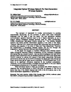
Abstract In current and next generation high speed optical transmission systems, adaptive distortion compensation is of high interest. With increasing bitrates and an increasing complexity of the optical layer, the sources for signal distortions are increasing. The dynamic changes of the transmission channel due chromatic dispersion (CD), polarization mode dispersion (PMD) and nonlinear distortions, such as self-phase modulation (SPM), easily exceed the tolerable amount for an error free operation of the transmission system. To compensate for these time and frequency varying distortions and to meet the system tolerances, a static compensation approach is not sufficient anymore and an adaptive solution for equalization is necessary. Optical equalizers have advantages in comparison to electrical ones [1-2], as they are not bitrate limited due to the electronics and operate in front of the nonlinear photodiode. Reported optical adaptive equalization experiments compensate either for chromatic dispersion or polarization mode dispersion by devices that model the inverse system, e.g. CD compensation by fiber bragg gratings (FBG), integrated IIR- and FIR- filter structures or PMD compensation by cascaded polarization control and birefringent elements, [3-7]. Integrated optical FIR- and IIR-filter have a periodic frequency response, tunable center wavelength and a large variability in compensating for distorting effects, such as CD, higher order dispersion, SPM and PMD [6,8-10]. By matching the frequency response periodicity (i.e. the free spectral range (FSR)) to the channel grid, a single filter can equalize a number of WDM channels simultaneously. IIR filters are based on ring resonators or etalons. The FSR is determined by the absolute path length of the feedback, which makes it difficult to realize a bandwidth of 50GHz and more. Planar lightwave circuit (PLC) integrated FIR lattice filters can be implemented by cascading symmetrical and asymmetrical Mach-Zehnder Interferometer (MZI), Fig.1. In contrast to optical IIR-filters, FIR-filters are feed forward filters and the FSR is given by the differential path difference. A large bandwidth of 100GHz or more can be easily achieved. The device was designed and fabricated using the IBM high-index-contrast SiON technology [11]. The die size is 16 × 12 mm.
thermo-optic phase shift 3dB coupler
delay line Td
asymmetrical MZI symmetrical MZI
Fig. 1. schematic structure of an integrated optical FIR lattice filter: cascaded symmetrical and asymmetrical Mach-Zehnder Interferometer
Criteria for the adaptive control have been proposed in the time and in the frequency domain as well, e.g. eye opening, Q-factor or bit error rate and vestigal side band filtering, spectral broadening through a Kerr nonlinearity or monitoring a subcarrier, the clock intensity or the electrical spectrum [1216]. We chose electrical spectrum monitoring as adaptive feedback for simultaneous CD and PMD compensation with PLC integrated optical FIR-filters, because of its sensitivity to both and its simplicity and ease of implementation [9], section A. The classical adaptive equalization approach in communication theory, the minimization of the intersymbol interference with electrical FIR-filters and a Least Mean Square error algorithm is transferred into the optical domain in section B, [8,10].
A. Simultaneous adaptive CD and PMD equalization with electrical spectrum monitoring as adaptive feedback In contrast to the time and optical frequency domain criteria, adaptive feedback solutions within the electrical spectrum are fast, inexpensive and easy to implement by electrical bandpass filters and power monitoring. We demonstrate a strategy of monitoring a single frequency for combined adaptive th CD and PMD compensation in a 40Gb/s NRZ transmission setup with integrated optical 6 order FIRfilters filter of a FSR=100GHz, Fig.2. pattern generator
integrated optical 6th order FIRLattice Filter (pol. splitted setup)
101
laser
Rx
SSMF, DCF with variable PMD emulator length EDFA
VOA
PBS
BER
EDFA ASE-filter
scope transmission chanel
PD
adaptive filter control
bp-filter, f0=20GHz
feedback signal
Fig. 2. System setup: simultaneous adaptive CD and PMD compensation with PLC integrated optical FIR lattice filters
Signal distortions are determined through changes of the transfer function of the optical fiber. The optical fiber transfer function is reflected in the power spectral density or the electrical spectrum of the received signal. Monitoring the power of the bandpass filtered received electrical signal for various dispersion values results in an oscillating characteristic with a global maximum (f05
10
0
4
1
2
dgd (ps)
15
0.5
1
dispersion (ps/nm)
4
20
EOP with equalizer 1 >5 2
1
0 20 60 100 140 180
3
25
0.5
1 0. 5 5
2
3 2
10
b.)
1
>5
3
15 2
4
0
2
20 4
EOP w/o equalizer
5
25
>5
a.)
0 20 60 100 140 180
dispersion (ps/nm)
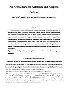
Fig. 6. Simulation results: simultaneous adaptive compensation of CD and PMD, EOP without (a) and with equalizer (b).
The characteristic 1dB EOP line is increased from D=60ps/nm and DGD=12ps without equalizer up to D=140ps/nm and DGD=24ps with equalizer. Exceeding the operation range leads the adaptive algorithm to converge into a local maximum. To increase the operation range, the bandpass filter frequency has to be decreased or combined with bandpass filters of lower center frequency.
B. Intersymbol Minimization with a Least Mean Square Error Algorithm
A common approach for adaptive filtering and equalization in communications theory is to use the ISI in a mean square error formulation as feedback criterion for the filter control. We use an optical FIR-filter for equalization in the optical domain and measure the ISI mean square error behind the photodiode in the electrical domain, Fig.7. Tx
transmission optical equalizer chanel
decision circuit
PD
y(n)
+ LMSAlgorithm
Σ
d(n)
Fig. 7 adaptive equalization setup, minimization of the ISI with an optical FIR-filter and a LMS-Algorithm
3 2
GHz =80 FSR
1 00
R FS
Hz 0G 0 =1
100
200
300
400
500
dispersion (ps/nm) Fig. 8 EOP due to accumulated dispersion at 40Gb/s, w/o equalizer and with 10th order optical FIR-filter
eye opening penalty (dB)
4
FSR= 400G Hz FS R= 20 0G Hz
5 no eq ualize r
eye opening penalty (dB)
For equalization, a modified Least Mean Square (LMS) algorithm iterates each coefficient of the optical FIR-filter in the direction of the gradient of the feedback signal, the MSE of the photodetected y(n) and desired or training sequence d(n). To evaluate the equalizer performance, the dispersion tolerance of a single channel for linear and nonlinear transmission is simulated, Fig.8,9. The FSR and power levels are varied. In a linear 40Gb/s NRZ coded transmission, the dispersion tolerance referenced to an EOP of 1dB th is approximately D=±60ps/nm. With a 10 order FIR-filter and the adaptive minimization of the ISI the dispersion tolerance can be increased up to D=±200ps/nm for a FSR of 80GHz, Fig 8. 5 4
9dBm no equalizer 12dBm with equalizer
3 2 1 9dBm with equalizer 0 -300 -200 -100
0
100
200
300
dispersion (ps/nm) Fig. 9 EOP due to SPM and accumulated dispersion at 40Gb/s, w/o equalizer and with 10th order optical FIRfilter
For the most efficient equalization, the impulse response for a given filter order should be as long as possible. Therefore, the FSR has to be chosen as small as possible, but additional penalties due to bandwidth narrowing have to be avoided. The optimum FSR is between FSR=80…100GHz, which corresponds to a tap delay of T=2…2.5 fBit. In a nonlinear transmission, not only an increased dispersion tolerance, but also SPM equalization can be realized. A transmission system consisting of 100km SSMF and optimal dispersion compensation with DCF, results in a minimum EOP of approximately 1dB for a launch power of Plaunch=9dBm, Fig.9. With the adaptive optical FIR-filter, the minimum EOP can be reduced to 0.5dB and the dispersion tolerance increased up to the range of D=-100…+200ps/nm. Further on, a minimum EOP of 1dB, as in the unequalized Plaunch=9dBm case, can be reached at a better dispersion tolerance by equalizing the same transmission setup with a launch power of Plaunch=12dBm. This is a SPM equalizing gain of 3dB.
Conclusion Planar lightwave circuit integrated optical FIR-filters are small, easy and fast tunable by the thermo-optic effect. As they can realize an arbitrary transfer function, they are a powerful device for compensating fiber channel impairments. Electrical spectrum monitoring is an easy to implement solution for the adaptive control of the optical FIR-filter. The most effective approach for the adaptive
filter control is the minimization of the intersymbol interference in a MSE formulation with a LMS error algorithm, but difficult to implement at high bitrates.
References [1] [2] [3]
[4] [5] [6] [7] [8] [9]
[10] [11] [12] [13]
[14]
[15] [16]
S.Otte et al., “Performance of electronic compensators for chromatic dispersion and SPM”, ECOC 2000, Munich, paper 3.2.6. H.Bülow et al., “Electronic PMD mitigation – from linear equalization to maximum-likelihood detection”, OFC 2001, Anaheim, paper WAA3-2. M.Sumetsky et al., “High-performance 40Gb/s fibre bragg grating tunable dispersion compensator fabricated using group delay ripple correction technique”, Electronics Letters, Vol.39, N0.16, 2003, pp. 1196-1198. D.J.Moss et al., “Multichannel tunable dispersion compensation using all-pass multicavity etalons”, OFC 2002, FA6 F.Horst et al., “Tunable ring resonator dispersion compensators realized in high refractive index contrast SiON technology”, ECOC 2000, paper PD2.2. M.Bohn et al., “Tunable dispersion compensation in a 40Gb/s system using a compact FIRlattice filter in SiON technology”, ECOC 2002, paper 4.2.1 . R.Noe et al., “Polarization mode dispersion compensation at 10, 20, 40Gb/s with various optical equalizers”, Journal of Lightwave Technology, Vol.17,1999, pp.1602-1616. M.Bohn et al., “An adaptive optical equalizer concept for single channel distortion compensation”, ECOC 2001, paper Mo.F.2.3. M.Bohn et al., “Simultaneous adaptive equalization of group velocity and polarization mode dispersion at 40Gb/s with integrated optical FIR-filters and electrical spectrum monitoring as feedback”, ECOC 2003, paper Th.2.2.4. M.Bohn et al., “Adaptive Polarization Mode Dispersion Compensation at 40Gb/s with Integrated Optical Finite Impulse Response (FIR) Filters”, NFOEC 2002 G.-L.Bona et al., “SiON high refractive-index waveguide and planar lightwave circuits”, IBM J. Res.&Dev., Vol.47, No.2/3, 2003, pp.239-249 F.Buchali et al., “Fast eye opening monitor for 10Gb/s and its application for optical PMD compensation”,OFC 2001, Anaheim, paper TuP5. Q.Yu et al., “Chromatic dispersion monitoring technique using sideband optical filtering and clock phase-shift detection”, Journal of Lightwave Technology, Vol.20, N0.12, 2002, pp. 22672271. P.S.Westbrook et al., “Measurement of residual chromatic dispersion of a 40Gb/s RZ signal via spectral broadening”, IEEE Photonics Technology Letters, Vol.14, No.3, 2002, pp. 346248. M.N.Petersen et al., “Dispersion monitoring and compensation using a single inband subcarrier tone”, OFC, 2000, Baltimore, paper WH4-1. A.Sano et al., “Extracted-clock power level monitoring scheme for automatic dispersion equalization in high speed optical transmission systems”, IEICE Trans. Commun., Vol. E84B, No.11, 2001, pp. 2907-2914.