or run-time adaptation of application behavior to facilitate better performance combined ... development of middleware for self-configurable systems in the automotive sector. ...... cellphones such as the iPhone â that are less restricted than other embedded systems ..... at least partly, incompatible tools with custom features.
Adaptive Middleware for Self-Configurable Embedded Real-Time Systems
Experiences from the DySCAS Project and Remaining Challenges
N B MAGNUS PERSSON
Licentiate Thesis Stockholm, Sweden 2009
TRITA MMK 2009-22 ISSN 1400-1179 ISRN KTH/MMK/R--09/22--SE ISBN 978-91-7415-495-5
KTH School of Industrial Technology and Management SE-100 44 Stockholm SWEDEN
Akademisk avhandling som med tillstånd av Kungl Tekniska högskolan framlägges till offentlig granskning för avläggande av teknologie licentiatexamen i maskinkonstruktion torsdagen den 19 nov 2009 klockan 14.00 i seminarierum B242, Institutionen för Maskinkonstruktion, Kungl Tekniska högskolan, Brinellvägen 83, Stockholm. © N B Magnus Persson, oktober 2009 Tryck: E-print
Abstract Development of software for embedded real-time systems poses several challenges. Hard and soft constraints on timing, and usually considerable resource limitations, put important constraints on the development. The traditional way of coping with these issues is to produce a fully static design, i.e. one that is fully fixed already during design time. Current trends in the area of embedded systems, including the emerging openness in these types of systems, are providing new challenges for their designers – e.g. integration of new software during runtime, software upgrade or run-time adaptation of application behavior to facilitate better performance combined with more efficient resource usage. One way to reach these goals is to build self-configurable systems, i.e. systems that can resolve such issues without human intervention. Such mechanisms may be used to promote increased system openness. This thesis covers some of the challenges involved in that development. An overview of the current situation is given, with a extensive review of different concepts that are applicable to the problem, including adaptivity mechanisms (incluing QoS and load balancing), middleware and relevant design approaches (component-based, model-based and architectural design). A middleware is a software layer that can be used in distributed systems, with the purpose of abstracting away distribution, and possibly other aspects, for the application developers. The DySCAS project had as a major goal development of middleware for self-configurable systems in the automotive sector. Such development is complicated by the special requirements that apply to these platforms. Work on the implementation of an adaptive middleware, DyLite, providing self-configurability to small-scale microcontrollers, is described and covered in detail. DyLite is a partial implementation of the concepts developed in DySCAS. Another area given significant focus is formal modeling of QoS and resource management. Currently, applications in these types of systems are not given a fully formal definition, at least not one also covering real-time aspects. Using formal modeling would extend the possibilities for verification of not only system functionality, but also of resource usage, timing and other extra-functional requirements. This thesis includes a proposal of a formalism to be used for these purposes. Several challenges in providing methodology and tools that are usable in a production development still remain. Several key issues in this area are described, e.g. version/configuration management, access control, and integration between different tools, together with proposals for future work in the other areas covered by the thesis. Keywords: adaptivity, embedded real-time systems, DySCAS, DyLite, quality of service (QoS), load balancing, resource constraints, model-based design, component-based design, software architecture, adaptive middleware
iii
Sammanfattning Utveckling av mjukvara för inbyggda realtidssystem innebär flera utmaningar. Hårda och mjuka tidskrav, och vanligtvis betydande resursbegränsningar, innebär viktiga inskränkningar på utvecklingen. Det traditionella sättet att hantera dessa utmaningar är att skapa en helt statisk design, d.v.s. en som är helt fix efter utvecklingsskedet. Dagens trender i området inbyggda system, inräknat trenden mot systemöppenhet, skapar nya utmaningar för systemens konstruktörer – exempelvis integration av ny mjukvara under körskedet, uppgradering av mjukvara eller anpassning av applikationsbeteende under körskedet för att nå bättre prestanda kombinerat med effektivare resursutnyttjande. Ett sätt att nå dessa mål är att bygga självkonfigurerande system, d.v.s. system som kan lösa sådana utmaningar utan mänsklig inblandning. Sådana mekanismer kan användas för att öka systemens öppenhet. Denna avhandling täcker några av utmaningarna i denna utveckling. En översikt av den nuvarande situationen ges, med en omfattande genomgång av olika koncept som är relevanta för problemet, inklusive anpassningsmekanismer (inklusive QoS och lastbalansering), mellanprogramvara och relevanta designansatser (komponentbaserad, modellbaserad och arkitekturell design). En mellanprogramvara är ett mjukvarulager som kan användas i distribuerade system, med syfte att abstrahera bort fördelning av en applikation över ett nätverk, och möjligtvis även andra aspekter, för applikationsutvecklarna. DySCAS-projektet hade utveckling av mellanprogramvara för självkonfigurerbara system i bilbranschen som ett huvudmål. Sådan utveckling försvåras av de särskilda krav som ställs på dessa plattformar Arbete på implementeringen av en adaptiv mellanprogramvara, DyLite, som tillhandahåller självkonfigurerbarhet till småskaliga mikrokontroller, beskrivs och täcks i detalj. DyLite är en delvis implementering av koncepten som utvecklats i DySCAS. Ett annat område som får särskild fokus är formell modellering av QoS och resurshantering. Idag beskrivs applikationer i dessa områden inte helt formellt, i varje fall inte i den mån att realtidsaspekter täcks in. Att använda formell modellering skulle utöka möjligheterna för verifiering av inte bara systemfunktionalitet, men även resursutnyttjande, tidsaspekter och andra icke-funktionella krav. Denna avhandling innehåller ett förslag på en formalism som kan användas för dessa syften. Det återstår många utmaningar innan metodik och verktyg som är användbara i en produktionsmiljö kan erbjudas. Många nyckelproblem i området beskrivs, t.ex. versions- och konfigurationshantering, åtkomststyrning och integration av olika verktyg, tillsammans med förslag på framtida arbete i övriga områden som täcks av avhandlingen. Nyckelord: anpassningsbarhet, inbyggda realtidssystem, DySCAS, DyLite, servicekvalitet (QoS), lastbalansering, resursbegränsningar, modellbaserad design, komponentbaserad design, mjukvaruarkitektur, adaptiv mellanprogramvara
iv
Preface I’d like to send immense thanks to my coworkers in the Embedded Control Systems Research Group at KTH - Martin Törngren and DeJiu Chen who have been my supervisors, Tahir Naseer Qureshi who started slightly earlier than me and with whom I have cooperated a lot with throughout the DySCAS project, as have Lei Feng and Javier García, and all the others who have helped to provide me with a good working environment. Naturally, additional thanks go to the projects that have funded my research. The main ones are DySCAS and FRAMES, with smaller contributions from Artist2, ArtistDesign, ARTES and CESAR. Further thanks go to all the partners within the DySCAS project, which has been the basis for this research. I would also like to thank my parents, siblings, and friends who have supported me outside of KTH. Sincere thanks!
Stockholm, Sweden November 6, 2009
v
Pro captu lectoris habent sua fata libelli.
vi
Contents
Preface
v
Contents
vii
List of Appended Papers
xi
List of Other Publications
xiii
Reading Guideline
xv
1 Setting the Scene 1.1 An Example Application: Vehicle Stability Control 1.2 Definitions of Key Concepts . . . . . . . . . . . . . 1.3 Development Tools and Processes . . . . . . . . . . 1.4 Industrial Context and Scientific Challenges . . . . 1.5 The DySCAS Project . . . . . . . . . . . . . . . . . .
. . . . .
1 2 3 5 5 7
2 Research Goal and Document Structure 2.1 Research Objectives . . . . . . . . . . . . . . . . . . . . . . . . . . . 2.2 Thesis Structure and Contribution . . . . . . . . . . . . . . . . . . .
9 9 11
3 Background and Industrial Motivation 3.1 Conventional Design Process of Automotive Embedded Systems 3.2 Modularity . . . . . . . . . . . . . . . . . . . . . . . . . . . . . . . 3.3 Dynamic Reconfigurability and Self-Configurability . . . . . . . 3.4 Degree of Adaptation: a Continuum of Multiple Dimensions . .
. . . .
13 13 16 18 19
4 State of the Art in the Development of Embedded Systems 4.1 Architectural design . . . . . . . . . . . . . . . . . . . . . 4.2 Model-based Design and Engineering . . . . . . . . . . . 4.3 Component-Based Design . . . . . . . . . . . . . . . . . 4.4 Support Tools – Gap Analysis . . . . . . . . . . . . . . . 4.5 Discussion . . . . . . . . . . . . . . . . . . . . . . . . . .
. . . . .
21 21 23 26 30 31
vii
. . . . .
. . . . .
. . . . .
. . . . .
. . . . .
. . . . .
. . . . .
. . . . .
. . . . .
. . . . .
. . . . .
. . . . .
. . . . .
5 Middleware 5.1 Transparencies . . . . . . . . . 5.2 Taxonomy of Middlewares . . 5.3 Adaptive Middleware . . . . . 5.4 A Few Middleware Examples 5.5 Discussion . . . . . . . . . . .
. . . . .
. . . . .
. . . . .
. . . . .
. . . . .
. . . . .
. . . . .
. . . . .
. . . . .
. . . . .
. . . . .
. . . . .
. . . . .
. . . . .
. . . . .
. . . . .
. . . . .
. . . . .
33 34 35 36 37 45
6 Adaptivity 6.1 Quality of Service . . . . . . . . . . . 6.2 Load Balancing . . . . . . . . . . . . 6.3 Admission Control . . . . . . . . . . 6.4 Generalized Adaptivity . . . . . . . . 6.5 Control-Theoretic View of Adaptivity 6.6 Metrics of Configuration Quality . . 6.7 Discussion . . . . . . . . . . . . . . .
. . . . . . .
. . . . . . .
. . . . . . .
. . . . . . .
. . . . . . .
. . . . . . .
. . . . . . .
. . . . . . .
. . . . . . .
. . . . . . .
. . . . . . .
. . . . . . .
. . . . . . .
. . . . . . .
. . . . . . .
. . . . . . .
. . . . . . .
47 47 49 50 50 50 52 52
7 Design and Implementation of an Adaptive Middleware 7.1 Major Design Principles behind DySCAS . . . . . . . . . . . . . . . 7.2 Implementing DySCAS . . . . . . . . . . . . . . . . . . . . . . . . . 7.3 Discussion . . . . . . . . . . . . . . . . . . . . . . . . . . . . . . . .
53 53 55 56
8 Formal Modeling of Extra-Functional Properties 8.1 Overview of Formal Approaches . . . . . . . . . . . . . . . . . . . . 8.2 A Proposed Resource Modeling Formalism . . . . . . . . . . . . . .
57 57 58
9 Discussion 9.1 Contribution and Validity . . . . . . . . . . . . . . . . . . . . . . . 9.2 Possible Future Work . . . . . . . . . . . . . . . . . . . . . . . . . . 9.3 End Words . . . . . . . . . . . . . . . . . . . . . . . . . . . . . . . .
59 60 61 66
References
67
. . . . .
. . . . .
. . . . .
Appended paper A Suitability of Dynamic Load Balancing in Resource-Constrained Embedded Systems A.1 Introduction . . . . . . . . . . . . . . . . . . . . . . . A.2 Introducing Load Balancing . . . . . . . . . . . . . . A.2.1 Load Balancing Viewed as a Control Problem A.3 Key Design and Implementation Issues . . . . . . . . A.3.1 Real-Time Requirements . . . . . . . . . . . . A.3.2 Conflicts with other Mechanisms . . . . . . . A.3.3 Design Issues . . . . . . . . . . . . . . . . . . A.3.4 Detection and Sensing Issues . . . . . . . . . A.3.5 Decision and Control Issues . . . . . . . . . . viii
. . . . . . . . .
. . . . . . . . .
. . . . . . . . .
. . . . . . . . .
. . . . . . . . .
. . . . . . . . .
. . . . . . . . .
. . . . . . . . .
A1 A1 A2 A3 A3 A4 A5 A5 A6
A.3.6 Actuation Issues . . . . . . . . . . . . . . . . . . . . . . . . . A.4 Conclusions . . . . . . . . . . . . . . . . . . . . . . . . . . . . . . . References . . . . . . . . . . . . . . . . . . . . . . . . . . . . . . . . . . .
A6 A6 A7
Appended paper B DyLite: Design, Implementation and Experiences of a Light-Weight Middleware for Adaptive Embedded Systems B.1 Introduction . . . . . . . . . . . . . . . . . . . . . . . . . . . . . . . B1 B.1.1 Motivation and Aim . . . . . . . . . . . . . . . . . . . . . . B2 B.1.2 Delimitations . . . . . . . . . . . . . . . . . . . . . . . . . . B2 B.2 Background . . . . . . . . . . . . . . . . . . . . . . . . . . . . . . . B4 B.2.1 DySCAS . . . . . . . . . . . . . . . . . . . . . . . . . . . . . B4 B.2.2 SHAPE . . . . . . . . . . . . . . . . . . . . . . . . . . . . . . B7 B.2.3 SAINT . . . . . . . . . . . . . . . . . . . . . . . . . . . . . . B12 B.3 Analysis of Requirements and High-Level Design Constraints . . . B17 B.3.1 Requirements on the DyLite Experimental Platform . . . . B17 B.3.2 Evaluated General Requirements and Evaluated Aspects . B17 B.3.3 Validation Test Cases . . . . . . . . . . . . . . . . . . . . . . B19 B.3.4 Hardware Constraints . . . . . . . . . . . . . . . . . . . . . B20 B.3.5 Demonstration Scenarios . . . . . . . . . . . . . . . . . . . . B20 B.4 Architecture and detailed design . . . . . . . . . . . . . . . . . . . B21 B.4.1 Mapping of DyLite to the DySCAS Reference Architecture B22 B.4.2 Control Structure . . . . . . . . . . . . . . . . . . . . . . . . B23 B.4.3 Task Model . . . . . . . . . . . . . . . . . . . . . . . . . . . . B23 B.4.4 Communication Model: Protocol and Communication Stack B25 B.4.5 Resource Model . . . . . . . . . . . . . . . . . . . . . . . . . B28 B.4.6 QoS Mechanisms . . . . . . . . . . . . . . . . . . . . . . . . B29 B.4.7 Self-Configuration Algorithm . . . . . . . . . . . . . . . . . B30 B.4.8 DyLite API . . . . . . . . . . . . . . . . . . . . . . . . . . . . B30 B.5 Implementation . . . . . . . . . . . . . . . . . . . . . . . . . . . . . B31 B.5.1 Movimento Puma . . . . . . . . . . . . . . . . . . . . . . . . B31 B.5.2 Freescale MCF5213 evaluation boards . . . . . . . . . . . . B32 B.5.3 GNU/Linux PC . . . . . . . . . . . . . . . . . . . . . . . . . B32 B.6 Demonstration . . . . . . . . . . . . . . . . . . . . . . . . . . . . . . B33 B.6.1 Embedded Scenario: Reconfigurability and Quality of Service B33 B.6.2 Resource Rich Scenario: Audio Streaming and Quality of Service . . . . . . . . . . . . . . . . . . . . . . . . . . . . . . B35 B.6.3 Resource Rich Scenario: Interaction with and Control of Legacy Hardware . . . . . . . . . . . . . . . . . . . . . . . . B36 B.7 Conclusions . . . . . . . . . . . . . . . . . . . . . . . . . . . . . . . B37 B.7.1 Research Questions Revisited . . . . . . . . . . . . . . . . . B38 B.7.2 Possible Implementation Variations to Consider . . . . . . . B39 B.7.3 Future Work . . . . . . . . . . . . . . . . . . . . . . . . . . . B40 References . . . . . . . . . . . . . . . . . . . . . . . . . . . . . . . . . . . B41 ix
Appended paper C Towards Model-Based Engineering of Self-Configuring Embedded Systems C.1 Introduction . . . . . . . . . . . . . . . . . . . . . . . C.2 Capabilities . . . . . . . . . . . . . . . . . . . . . . . . C.3 Case Study . . . . . . . . . . . . . . . . . . . . . . . . C.3.1 Architecture Modelling with UML . . . . . . C.3.2 Verification and Validation through Analysis C.3.3 Run-Time Models . . . . . . . . . . . . . . . . C.4 Conclusions and future work . . . . . . . . . . . . . . References . . . . . . . . . . . . . . . . . . . . . . . . . . .
. . . . . . . .
. . . . . . . .
. . . . . . . .
. . . . . . . .
. . . . . . . .
. . . . . . . .
. . . . . . . .
. . . . . . . .
Appended paper D A Timed Automata Formalism for Modeling Resource Management and Quality of Service in Real-Time Contexts Used Notation . . . . . . . . . . . . . . . . . . . . . . . . . . . . . . . . . D.1 Introduction . . . . . . . . . . . . . . . . . . . . . . . . . . . . . . . D.1.1 Aim of the Formalism Presented . . . . . . . . . . . . . . . D.1.2 Related Work . . . . . . . . . . . . . . . . . . . . . . . . . . D.1.3 Requirements Analysis . . . . . . . . . . . . . . . . . . . . . D.2 Theory of Timed Automata . . . . . . . . . . . . . . . . . . . . . . . D.2.1 Definition of Timed Automata . . . . . . . . . . . . . . . . . D.2.2 Operations on Timed Automata . . . . . . . . . . . . . . . . D.3 An Extensible Framework for Resource Modeling . . . . . . . . . . D.3.1 Task model . . . . . . . . . . . . . . . . . . . . . . . . . . . . D.3.2 Resource Models . . . . . . . . . . . . . . . . . . . . . . . . D.3.3 Contracts and Negotiation . . . . . . . . . . . . . . . . . . . D.3.4 Modeling of Resource Management and QoS Mechanisms . D.3.5 Utility Functions . . . . . . . . . . . . . . . . . . . . . . . . D.3.6 Adaptability . . . . . . . . . . . . . . . . . . . . . . . . . . . D.3.7 Static Adaptability . . . . . . . . . . . . . . . . . . . . . . . D.3.8 Dynamic Adaptability . . . . . . . . . . . . . . . . . . . . . D.3.9 Configuration Reasoning . . . . . . . . . . . . . . . . . . . . D.4 Instantiation of the Framework . . . . . . . . . . . . . . . . . . . . D.4.1 Example: DyLite . . . . . . . . . . . . . . . . . . . . . . . . D.4.2 Other Instantiation Scenarios . . . . . . . . . . . . . . . . . D.5 Discussion . . . . . . . . . . . . . . . . . . . . . . . . . . . . . . . . D.5.1 Suitable Levels of Approximation . . . . . . . . . . . . . . . D.5.2 Semantic Weaknesses . . . . . . . . . . . . . . . . . . . . . . D.5.3 Applying the Framework for Other Purposes . . . . . . . . D.6 Future Work . . . . . . . . . . . . . . . . . . . . . . . . . . . . . . . D.6.1 Practically Oriented Ideas . . . . . . . . . . . . . . . . . . . D.6.2 Further Extensions of the Formalism . . . . . . . . . . . . . References . . . . . . . . . . . . . . . . . . . . . . . . . . . . . . . . . . . x
C1 C2 C5 C5 C6 C7 C7 C7
D1 D2 D2 D3 D7 D9 D9 D11 D11 D11 D12 D14 D14 D15 D15 D15 D15 D15 D16 D16 D18 D19 D19 D20 D20 D20 D20 D21 D22
List of Appended Papers Paper A Suitability of Dynamic Load Balancing in Resource-Constrained Embedded Systems: An Overview of Challenges and Limitations Magnus Persson, Tahir Naseer Qureshi, and Martin Törngren, presented at Workshop on Adaptive and Reconfigurable Embedded Systems (APRES’08), St. Louis, MO, USA, April 21, 2008. The paper was mainly written in close cooperation by Magnus Persson and Tahir Naseer Qureshi. Martin Törngren provided vital feedback, suggestions for improvements and help in planning the structure.
Paper B DyLite: Design, Implementation and Experiences of a Light-Weight Middleware for Adaptive Embedded Systems Magnus Persson, Javier García, Lei Feng, Tahir Naseer Qureshi, DeJiu Chen, Martin Törngren, technical report, KTH, Stockholm, 2009, TRITA MMK 2009:06, ISSN 1400-1179, ISRN/KTH/MMK/R-09/06-SE. Magnus Persson led the work. Javier García and Magnus Persson worked on the communication protocol and communication stack. Lei Feng provided a reconfiguration algorithm, and also worked on the task model, resource models, and QoS mechanism design. Magnus Persson programmed the Freescale MCF5213 evaluation boards and Javier García the Movimento Puma and integrated DyLite through a gateway to the SAINT system. Tahir Naseer Qureshi, DeJiu Chen and Martin Törngren provided feedback and useful advice.
xi
Paper C Towards Model-Based Engineering of Self-Configuring Embedded Systems DeJiu Chen, Martin Törngren, Magnus Persson, Lei Feng and Tahir Naseer Qureshi, book chapter to appear in Model-Based Engineering of Embedded Real-Time Systems, Holger Giese, Bernard Rumpe, Bernard Schätz (eds), Springer Verlag, 2009. DeJiu Chen and Martin Törngren led the work on the paper. The remaining authors all contributed equally to the general ideas. Magnus Persson specifically provided input for the section on run-time models.
Paper D A Timed Automata Formalism for Modeling Resource Management and Quality of Service in Real-Time Contexts Magnus Persson, Lei Feng, Martin Törngren, technical report, KTH, Stockholm, 2009, TRITA MMK 2009:21, ISSN 1400-1179, ISRN/KTH/MMK/R-09/21-SE Magnus Persson was the main author of the report, and was the originator of the described ideas. Lei Feng and Martin Törngren provided helpful feedback and help in writing the report.
xii
List of Other Publications Using Improved Resource Interfaces to Formally Describe Adaptability in Embedded Systems Magnus Persson and Martin Törngren, presented at 2nd Workshop on Adaptive and Reconfigurable Embedded Systems (APRES), October 11, 2009, part of the Embedded Systems Week (ESWEEK), Grenoble, France. http://www.lulu.com/items/volume_66/7676000/7676758/2/print/7676758.pdf#page=33
Context-Aware Adaptation in DySCAS Richard Anthony, DeJiu Chen, Mariusz Pelc, Magnus Persson and Martin Törngren, in Electronic Communications of the EASST, vol. 19, 2009, presented at the Second International DisCoTec Workshop on Context-Aware Adaptation Mechanisms for Pervasive and Ubiquituos Services (CAMPUS 2009), Lisbon, Portugal, June 12, 2009. http://eceasst.cs.tu-berlin.de/index.php/eceasst/article/view/245/232
Model-Based Development of Middleware for Self-Configurable Embedded RealTime Systems: Experiences from the DySCAS Project Tahir Naseer Qureshi, Magnus Persson, DeJiu Chen, Martin Törngren and Lei Feng, presented at the Work-in-Progress session at Model-Driven Development for Distributed Real-Time Embedded Systems Summer School (MDD4DRES), Aussois, France, April 22, 2009. http://www.mdd4dres.info/_media/mdd4dreswip09_submission_13.pdf
On mapping UML models to Simulink/SimEvents: A Case Study of a Dynamically Self-Configuring Middleware Tahir Naseer Qureshi, DeJiu Chen, Martin Törngren, Lei Feng and Magnus Persson, technical report, KTH, Stockholm, 2009, report number TRITA-MMK 2009:05, ISSN 1400-1179, ISRN/KTH/MMK/R-09/05-SE http://www.sci.kth.se/polopoly_fs/1.18215!licavhandling.pdf#page=119
xiii
Experiences in Simulating a Dynamically Self-Configuring Middleware: A Case Study of DySCAS Middleware Tahir Naseer Qureshi, DeJiu Chen, Martin Törngren, Lei Feng and Magnus Persson, technical report, KTH, Stockholm, 2009, report number TRITA-MMK 2009:04, ISSN 1400-1179, ISRN/KTH/MMK/R-09/04-SE http://www.sci.kth.se/polopoly_fs/1.18215!licavhandling.pdf#page=81
Autonomic Middleware for Automotive Embedded Systems Richard Anthony, DeJiu Chen, Martin Törngren, Detlef Scholle, Martin Sanfridson, Achim Rettberg, Tahir Naseer Qureshi, Magnus Persson and Lei Feng, book chapter in Autonomic Communication, Athanassios Vasilakos, Manish Parashar, Stamatis Karnouskos and Witold Pedrysz (editors), Springer Verlag, 2009 Dynamic Configuration and Quality of Service in Autonomic Embedded Systems Lei Feng, DeJiu Chen, Magnus Persson, Tahir Naseer Qureshi and Martin Törngren, technical report, KTH, Stockholm, 2008, TRITA-MMK 2008:12, ISSN 14001179, ISRN/KTH/MMK/R-08/12-SE Survey on Dynamic Load Balancing in Distributed Computer Systems Magnus Persson and Tahir Naseer Qureshi, technical report, KTH, Stockholm, 2008, report number TRITA-MMK 2008:11, ISSN 1400-1179, ISRN/KTH/MMK/R-08/01-SE An Architectural Approach to Autonomics and Self-management in Automotive Embedded Electronic Systems DeJiu Chen, Richard Anthony, Magnus Persson, Detlef Scholle, Viktor Friesen, Gerrit deBoer, Achim Rettberg, and Cecilia Ekelin, presented at 4th European Congress Embedded Real Time Software (ERTS 2008), Toulouse, France, January 29–February 1, 2008 Simulation Tools for Dynamically Reconfigurable Automotive Embedded Systems: An Evaluation of TrueTime Tahir Naseer Qureshi, DeJiu Chen, Magnus Persson, and Martin Törngren, presented at Real-Time in Sweden (RTiS’07), Västerås, Sweden, August 21–22, 2007 http://www.kth.se/polopoly_fs/1.20317!licavhandling.pdf#page=51
Konstruktion av trådlös styrning för robottransportörer Magnus Persson, Master’s thesis, Chalmers University of Technology, Report ISSN 99-2747920-4 EX019/2007
xiv
Reading Guideline This thesis is a rather lengthy document, and all of it may not be relevant or even interesting to all readers. For the sake of helping you to find the most relevant parts of the thesis to read, the following guideline is given for readers of different types: • Layman: If you do not have any background in computer science or related fields, you probably read this thesis because you are a friend of the author. Supposedly, you are not interested in all the details. To understand the problems this thesis is trying to solve, you should read chapter 1 and 3, and to get an idea of what types of solutions are provided, then skip to chapter 9. • Computer engineer or similar: If you have a solid background in computers, but are not an expert in the areas covered by this thesis, the suggestion is that you also read chapters 5 through 6, to have an background understanding. After this, you can continue reading based on the expert reading recommendations for your main interest. • Expert: If you are an expert, you probably have one or several areas of interest, which are covered as listed below. – Middleware: The implementation of DyLite, a partial DySCAS implementation, is covered in chapter 7 and paper B. – Adaptivity: If you are an expert at adaptivity mechanisms, such as reconfiguration, QoS or load balancing, your main interest likely lies in chapter 6 and paper A . Further, in chapter 8 and paper D, a formal modeling framework for QoS and resource management is presented. – Tools and methodology: If you are an expert at developing tools for development of software for embedded systems, you are probably mostly interested in how adaptive middleware solutions will affect future development practices and tool requirements. These topics are mainly covered in sections 4.4, 9.2.2 and 9.2.3 and paper C. – Formal methods: Skip directly to paper D. Regardless of who you are - I hope you enjoy your reading! xv
Chapter 1
Setting the Scene Mechanical systems are increasingly being controlled by computers. Often, this technology combination is called mechatronics. Mechatronics is used in many domains; in this thesis mainly mechatronics in vehicles is under consideration. The computers performing the control of the mechanical part of the system are normally called embedded computers, defined by IEEE as: “A computer system that is part of a larger system and performs some of the requirements of that system; for example, a computer system used in an aircraft or rapid transit system.”[63] To develop software for computers with the purpose to control real-world machinery is significantly different from developing general-purpose software. Some special traits include that software running in embedded system is less easy to control and observe, compared to software on desktop computers. The reduced observability makes it harder to monitor, upgrade and debug. As an upside, these constraints make the incentive for a more structured system architecture larger, and the systems also typically (but not always) have a less complex architecture than e.g. desktop computers, as they – in contrast with PCs and other generalpurpose computers – are tailored for a certain task. Further, the physical laws of the computer’s surrounding environment implies strict constraints on how fast the computer performs its calculations, and the computer can hence be considered a real-time computer system: “Real time – pertaining to a system or mode of operation in which computation is performed during the actual time that an external process occurs, in order that the computation results can be used to control, monitor, or respond in a timely manner to the external process.”[63] Real time constraints can be further subdivided into hard and soft real-time properties. Hard real-time typically implies that the system’s functionality is 1
CHAPTER 1. SETTING THE SCENE
Appl. A
Appl. B
Middleware RTOS and HW drivers
Actu ator
Sen sor
Computer systems
2
Actu ator
Mechanical system
Appl. C
Middleware RTOS and HW drivers
Sen sor
Interconnecting network
Appl. D
Sen sor
Actu ator
Mechanical system
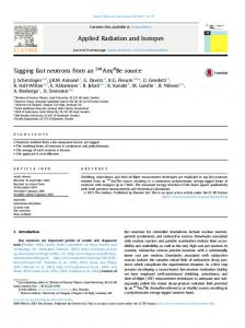
Figure 1.1: An illustration of a generic distributed mechatronic system, where the application software on each node is supported by a middleware. Two distributed control flows are indicated with arrows.
depending on the timing constraints being met. In soft systems, some timing violations are tolerated, as long as it normally does not happen. The complexity of these embedded computer systems is currently increasing, including the software deployed on them[50], a development which poses a significant development challenge. Different types of software may be used as a counter-measure.1 The scope of this thesis is to explore possible future support software, specifically middleware, extensively covered in chapter 5. An illustration of a typical, generic, setting is shown in figure 1.1. Development of complex, distributed systems (i.e. networked computer systems) take more and more development resources in current development projects in industry[130]. In addition to technical support in the form of tools, runtime support, etc, finding a good development method for such systems is a big research challenge for the embedded systems community. There is an obvious improvement potential in using a more organized and efficient development setting for the developers.
1.1
An Example Application: Vehicle Stability Control
As an example of a typical functionality affecting large parts of a distributed computer system, vehicle stability control will be described. This is a rather informal description; for detailed information about one example implementation, see e.g. [166]. The purpose of this functionality is to improve the vehicle’s driving 1 Different terms are used, depending on the nature of the software and the usage context.
Some common ones are middleware, support libraries, communication protocol, framework, virtual machine, run-time environment, etc.
1.2. Definitions of Key Concepts
3
Actual predicted trajectory VSC
BC
Expected trajectory
Figure 1.2: Illustration of vehicle stability control functionality. If the car deviates from its expected trajectory, the vehicle autonomously applies brakes individually at each wheel, together with throttle reduction, to keep the car on the road. The body cluster is marked “BC” and the vehicle stability control computer “VSC”.
characteristics in slippery road conditions. An overview image of a typical system is given in figure 1.2. The vehicle stability control compares the driver’s input (especially through the steering wheel) and uses it to calculate the driver’s expectation of the vehicle’s trajectory on the road. It then compares this trajectory with the vehicle’s actual trajectory, calculated from accelerometric data, typically from accelerometers and gyrometers in a node called the body cluster. If the trajectories deviate too much from each other, the computer concludes that steering control has been lost and the car is starting to skid. To avoid a crash, the car can then autonomously applies brakes to each wheel, to apply a turning moment to the car in the right direction. Although a similar corrective action could have been taken by the driver, vehicle stability control normally is far faster. To avoid driver overreliance on the feature, it is common to give an visual or audio warning when the function is activated. Vehicle stability control is a function which is very indicative of future car functionality. It includes several, different, physical systems in the car – brake controllers at each wheel, the steering wheel, sensors in the body cluster, and a central controller. By necessity this function has to be distributed over several nodes (centralizing sensing, processing and actuation to a single node would make cabling excessive), and includes several traditionally separate systems (brakes, steering, dashboard, stereo). It also has real-time requirements – its response has to be reliable and quick to be effective.
1.2
Definitions of Key Concepts
Many of today’s embedded systems are developed to be used in a closed setting; i.e. where the system does not change after its deployment. For example; many traditional networked embedded systems, e.g. within industrial automation and traditional automotive networks, have been designed with the assumption that no changes to the system will occur after deployment. This fact is currently being challenged by a trend towards open systems[50],
4
CHAPTER 1. SETTING THE SCENE
accessible for changes after their deployment and interoperable with other devices, which maybe not even were envisioned at the system development time. This trend is partly due to the systems being exposed to an increasing number of potential environment changes, that are simply not possible to handle with traditional design methods. Hence, the assumption that the system structure is known at design time no longer holds true[76]. More and more cooperating embedded systems will be composed in ways not foreseen at design time, with expectations on self-configuration. We define this term by first giving the definition for configuration: “The physical and logical elements (of a system), their assembly or composition, including their interconnections and admissible interactions, and the settings to select the admissible operational behaviors.” [15, 48, 136] “System Configuration – A particular arrangement and setup of data, functions, software components, hardware resources, as well as their relationships and properties that allows an embedded system to operate correctly according to its architecture.”[175] We also need to define the term component: “One of the parts that make up a system. A component may be hardware or software and may be subdivided into other components.” [48, 63] As is pointed out in this definition, components may consist of both hardware and software. Classical examples of hardware components include mechanical (cogwheels, nuts, bolts), electrical (resistors, diodes, batteries), pneumatic or hydraulic (pistons, valves), digital electronic (registers, ALUs, memories, processors) and so on. These are commonly standardized. There is an effort to provide similar types of system structure for software through software components. This is extensively discussed in section 4.3. With this definition in mind, the following definition of self-configuration will be used in this thesis:2 “The ability of a component to change its own configuration as a result of either internal or external influences.”[136] Self-configurable systems are a subset of adaptive systems. Adaptivity is a term applied to systems that are able to change themselves when their environment changes. The term is given a more rigorous coverage in chapter 6. One specific application area where a new approach may be beneficial is automotive embedded software. An example application scenario not supported 2 Although this definition uses the word component, we apply the definition to systems in general.
1.3. Development Tools and Processes
5
by the current software architectures is ad-hoc networking with mobile devices such as cell phones, PDAs, music players etc. Further, in most types of software, it is relatively common to have to make updates to the software after deployment. The reason for this could be desire to add new functionality, legislative changes or simply because of detected interoperability problems with other devices. Such updates are typically difficult to make in traditional embedded systems and require involvement of skilled workers.
1.3
Development Tools and Processes
All these trends jointly pose significant challenges on the development environment, specifically as many embedded computer systems also have real-time requirements. Most development tools make real-time properties a secondary or even disregarded property of the software, implying that it has to be handled separately. Usually this means these issues have to be resolved manually by engineers. It is a common approach to build static systems, where as many aspects as possible of the systems are fixed during development. Specifically, this usually includes allocation of tasks to processors, applications’ run modes, scheduling parameters (i.e. static schedules or fixed priorities), and even the exact version to be used (i.e it is hard to perform field upgrades). There is a continuum between fully static systems and dynamic systems. Unfortunately, building static systems may be an inefficient approach in some cases. This evolution also has a number of implications on future development processes for embedded systems. As system complexity grows, humans involved in the development of the systems need to increasingly rely on software tools to help them build systems, including the software used on them. These tools are traditionally used off-line, at system development time.
1.4
Industrial Context and Scientific Challenges
Several industrial requirements contribute to the complexity of the research. Users and developers of embedded systems often have quite specific requirements, even though they vary from domain to domain. The automotive industry is used as an example thereof below. To begin with, some automotive software is part of vehicle functions that are highly safety-critical, e.g. braking. This puts stringent requirements on the design process, including verification and validation. One of the traditional ways to provide less varying performance is to separate different parts of the vehicle network from each other. In automotive systems, the vehicular network is normally divided into 2–4 different domains, interconnected by gateways[101]. Common communication protocol choices are CAN[131], LIN[82, 83] and MOST[98]. An
6
CHAPTER 1. SETTING THE SCENE
Figure 1.3: A typical vehicle electrial architecture (simplified), in this example, three network layers are used: from left, vehicle, body and telematics/infotainment.
upcoming one is FlexRay[49]. As an example; three main networks is a common choice: • telematics, infotainment and other non-safety-critical functions, • the body domain where some, typically soft, real-time requirements are present, • the chassis domain, which includes hard real-time requirements from e.g. the brake controller, motor and gearbox. By using this system structure, isolation between different systems is achieved, so that, for example, the radio software can not impact the performance of the engine control unit causing hazards to the passengers. A simplified example architecture of this kind is shown in figure 1.3. These requirements, jointly with the vision of self-configuration, put a number of needs in focus: base technologies for dynamic reconfiguration of embedded systems, architectural guidelines and methods/tools for development of dynamically reconfigurable systems. This includes possible design patterns and tradeoffs between flexibility (including scalability, configurability and portability) on one hand and reliability, performance etc. on the other hand. Additionally, development of embedded software is normally limited by a number of requirements. There is a difference to other domains, in that requirements not only pose demands on what result is achieved, but also at what time it is delivered, i.e. significant real-time considerations come into play.
1.5. The DySCAS Project
1.5
7
The DySCAS Project
These challenges have all extensively been explored within the DySCAS3 project [42], focused on the automotive domain. The autonomic computing[62] approach has been one of the drivers for the work. DySCAS strives to develop a middleware for dynamically reconfigurable automotive systems to meet these new requirements[7]. This thesis summarizes the author’s experiences gained during the requirements elicitation, architecture and design work, verification and validation, and evaluation of the project results. It further points out some research challenges still left in the area, beyond the results achieved within DySCAS. The DySCAS project included several industrial partners – the software development company Enea, automotive OEM partners Daimler and Volvo Technology, the subsupplier Bosch GmbH, and two Swedish SMEs, Systemite (a tool vendor) and Movimento. Also, except from KTH, the University of Greenwich, University of Paderborn, and the Carl Ossietzky University of Oldenburg have been involved in the project. Key results from the project include an overview of state of the art in the area[8, 68], a reference architecture for middleware supporting self-configurable systems[175], several different partial implementations, each focusing on a specific part of the DySCAS concepts[154], and finally, an evaluation of the concepts[71]. At KTH, the work within the DySCAS project has focused on a number of areas: • Developing and documenting the DySCAS reference architecture, to be found in the project deliverable D2.3[175]. • Investigation on simulation of dynamically reconfigurable distributed systems, simulation tools and simulator requirements, documented in a parallel licentiate thesis[129]. • Developing algorithms capable of performing configuration autonomously during run-time, documented in [46, 47]. • Implementation of a proof-of-concept middleware based on the above mentioned architecture and algorithms. The middleware got the name DyLite4 , and is documented in paper B.
3 The acronym means “Dynamic Self-Configuring Automotive Systems” 4 DyLite is short for DySCAS Lite/QoS.
Chapter 2
Research Goal and Document Structure Below, an overview of the aim and structure of this thesis is given.
2.1
Research Objectives
The overall goal of the research leading up to this thesis has been to provide support for the development of adaptive middleware1 for self-configurable embedded systems; given constraints of both functional and extra-functional nature. The following subgoals have been identified: 1. To gain an overview of current state of the art in the areas of middleware, model- and component-based engineering, real-time computing, and adaptation mechanisms such as quality of service (QoS) and load balancing, particularly when these areas overlap. 2. Proof-of-concept implementation of an adaptive middleware for embedded real-time systems. 3. Develop a deeper understanding of adaptation mechanisms in the form of a formalized description of adaptability and resource usage of components and systems. 4. An understanding of the requirements on future tools and methodology for development of self-configurable systems, specifically in comparison with today’s situation.
2.1.1
Research Methodology
The research has been carried out in the following ways: 1 The term adaptive middleware is further elaborated in section 5.3.
9
10
CHAPTER 2. RESEARCH GOAL AND DOCUMENT STRUCTURE 1. Survey of state of the art and state of the practice, mainly through literature study, covering several topics: • The current, conventional design process of automotive embedded systems. • Middlewares, especially for embedded systems. • Adaptation mechanisms such as e.g. quality of service (QoS) and load balancing. • Component-based methodologies and different component models. • Architectural design. 2. Design work on DySCAS: • Participation in the design work on the DySCAS reference architecture and conceptual evaluation of different design alternatives. • Participation in modeling and simulation of the middleware, using model-based tools such as UML[167], Simulink[90], Stateflow[91], SimEvents[151] and TrueTime[115, 165]. • Implementation of a partial reference implementation of DySCAS, focusing on adaptivity in the form of reconfiguration and QoS. • Integration of the SAINT[134] truck as a demonstrator for the DySCAS project. 3. Synthesis and review, based on the collected information and developed results: • Consolidation of thoughts concerning the description of software components, specifically practically implementable formal descriptions of resource usage and other extra-functional properties in real-time component-based systems. • Gap analysis between tools and development methodologies used today and the ones that will be required in a future with self-configurable real-time systems. • Proposals for additional work, reaching beyond the work performed within the DySCAS project.
2.1.2
Delimitations
The following delimitations have been made, giving a main focus on the types of systems typically used in the automotive industry:
2.2. Thesis Structure and Contribution
11
• The focus of this thesis is on middleware. Hence, in this thesis, the mechanical and electronic part of the final system will be considered as an environment; co-design of mechanics and electronics is indeed possible, but out of scope for this thesis. Further, all application-oriented software, which is normally not available during the development of the support software, is also regarded as part of the middleware’s execution environment. Application software is still relevant, but only as a mold for the requirements on the middleware. • All practical evaluation was performed on computer systems realistically usable in automotive systems, i.e. microcontrollers in the lower price range, and using typical automotive networks, such as CAN. Different variants of control software were covered in addition to infotainment and multimedia. • Other types of middleware than message-based ones have only been covered in the literature study and not in practical work. Message-based middleware are the ones that seem most interesting for embedded control systems as they are provide more flexibility in communication patterns between applications. They have also been less well-studied by the traditional distributed systems community, which has focused a lot of work on middleware based on remote procedure calls (RPC), including object-based middleware. • Security and safety aspects, although interesting and important, were out of focus.
2.2
Thesis Structure and Contribution
The main contributions included as part of this thesis are listed below: • Overview of state of the art and practice – An overview of the current industrial development practice, presented in chapter 3, with a focus on how automotive embedded systems are developed today, and gives a business perspective on why dynamic reconfigurability may be advantageous in future embedded real-time systems. . – An overview of state of the art within the areas of model-based, component-based and architectural design presented in chapter 4. – An overview of a selection of middleware technologies are presented in chapter 5, – Chapter 6 provides an overview of different approaches to make systems adaptive, including quality of service (QoS) and load balancing. A comparison and consolidation of the different approaches is also given.
12
CHAPTER 2. RESEARCH GOAL AND DOCUMENT STRUCTURE – A presentation of the development of adaptive middleware in DySCAS in chapter 7. • A modeling formalism for resource management, quality of service, and similar issues in situations where real-time constraints apply, is briefly introduced in chapter 8. • Finally, a discussion on conclusions to be drawn from the work and suggestions for future work are given in chapter 9.
2.2.1
Brief Introduction of the Appended Papers
to provide more detailed information in several important areas, 4 papers have been appended to the thesis. The content of the appended papers has not been changed, with the exception of formatting changes and minor corrections. Additionally, the appendices have been left out of paper B, due to space constraints. The interested reader is referred to the original publication[124]. • Appended paper A is a workshop article covering the conceptual evaluation of dynamic load balancing in resource-constrained systems. This is included to show that dynamic reconfigurability is possible in the expected hardware environment. • Appended paper B is a technical report covering the design and implementation of DyLite, a partial implementation of the DySCAS architecture developed by the DySCAS project team at KTH. Its purpose has been to concretize, validate and demonstrate the DySCAS concepts in small embedded systems. • Appended paper C is a book chapter discussing tool integration and methodology in connection with DySCAS, specifically covering limitations in current product development environments and pointing towards a future model-based development approach for DySCAS-style systems. • Appended paper D is a technical report containing an outline of a formal modeling framework for resource management and QoS, providing a simple and accessible, yet powerful, versatile and extensible, framework for formal and quantitative modeling of resource usage and quality of service, applied to components in systems with hard and soft real-time requirements.
Chapter 3
Background and Industrial Motivation Embedded software development today poses significant challenges. Partly, this has been caused by a strive to include more functionality in the systems as their capabilities have increased[43, 50], putting an emphasis on the cost-efficient development of electronic embedded systems as an important research area in the automotive industry.[130] By including more functionality in essentially the same type of systems, the scalability of the development methods to larger system sizes has been tested. This significant challenge is proving problematic – the cost of development has increased significantly. To counter this development, the need for both well-functioning run-time support in the form of e.g. middleware, suitable design-time support through design and analysis tools, and more efficient development methods is obvious. The purpose of this chapter is to give a brief overview of the current state of the practice in embedded systems development, with a main perspective on the automotive one. Shortcomings and potential improvements will be identified together with current development trends in the embedded development world, and finally some expected changes beyond today’s practice. The problem description provided in this chapter will be used as a background for the rest of the thesis.
3.1
Conventional Design Process of Automotive Embedded Systems
The conventional design process of many embedded systems is typically based on some variation of the classic V-cycle[66] development process. One example of the V-cycle is described below in subsection 3.1.1, loosely based on input from several different sources[2, 101, 137, 171] covering mechatronics and embedded systems development in general or in the automotive systems specifically. In the automotive sector, this view of the development process is further complicated by the fact that cars are developed in a distributed fashion over borders between both companies and countries. The vehicle manufacturers – the 13
14
CHAPTER 3. BACKGROUND AND INDUSTRIAL MOTIVATION
Figure 3.1: One variation of the typical V-cycle development model.
OEMs1 – have the overall responsibility to create new car models, but a large part of it is in reality performed by tier one subsuppliers, which often take full responsibility for complete subsystems, including complete ECUs2 . This leads to a further complication, as it may lead to interest conflicts between the different partners, e.g. concerning who has the main responsibility for a certain function. As the supply chain crosses company borders, the process is often relatively formal, and to a large extent based on documents, e.g. specifications. Specifications are typically focused around the bus interfaces, describing how an ECU is allowed to communicate (signal exchange and functionality), as subsystems typically contain complete ECUs. For the system integrator, this implicitly also means that the developed ECUs need to be tested – both on their own, to validate that they have been correctly implemented, and together, to verify that no interoperability issues between ECUs from different vendors exist.
3.1.1
V-Cycle Development Model
First developed as a replacement of the early waterfall model, the V-cycle development model has since reached considerable utilization, especially in development of embedded systems. Several slightly different versions on the development model are available; one of these variations is presented in figure 3.1, explained below: 1. Requirements Analysis. The systems scope and requirements are decided upon, based on the needs of users and other stakeholders. 1 In the automotive industry, “OEM” has a different meaning compared to most other industries. In this context, an OEM is the company which puts the brandname on the car – i.e. Volvo or Scania. 2 ECU stands for Electronic Control Unit – a term used for embedded computers used in a car.
3.1. Conventional Design Process of Automotive Embedded Systems
15
2. Architecture Design. The requirements on the system are analyzed, and the architecture is chosen. The architecture consists of high-level structure and other fundamental design principles the system will be based on. 3. Component Design. Each of the components in the high-level structure is further specified. 4. Implementation. Using traditional coding and/or model-based approaches, each component is implemented according to its specification. 5. Component testing. Testing, and possibly other V&V approaches, are used to validate that the components have been implemented according to their specification. 6. Integration testing. The full system is assembled and tested in different ways for verification of the interaction between different components. 7. Validation. When the full system has been built, it is further evaluated to verify the requirements, maybe the system works as designed but is nonetheless not suitable due to a bad requirements analysis. Design feedback is not only given between successive design steps, but also on the same horizontal level, e.g. the design documents written in the requirements analysis, architecture design and component design phases are used in integration, component testing and validation. As previously stated, several variations of the V-cycle exist, however, they all follow the basic flow of more and more detailed specifications on one hand, and verification of the specifications as the implemented components are integrated thereafter. What mainly varies are the number of steps performed, their naming and content.
3.1.2
Organizational Limitations of the Design Process
The current design process has several significant limitations. Some of these are today not as relevant as they may become with some of the current development towards component-based approaches to software development in the automotive sector, described in subsection 3.2.2. • The process is heavily based on the assumption that separate organizations are involved in the development, however also that each of them develops complete hardware subsystems. This makes cooperation within a single ECU, implying significant resource sharing, problematic, as different partners’ contributions may interfere with eachother in unforeseen ways. • The workflow is to a big extent document-based, which typically means that specifications tend to become outdated as requirements change, and may cause erroneous or otherwise inconsistent documentation.
16
CHAPTER 3. BACKGROUND AND INDUSTRIAL MOTIVATION • Subsystem borders are commonly defined through organizational borders, not by technological constraints, which may lead to ineffecient architecture, especially as many new functions in cars are networked control functions. • Autosar[14] (see subsection 5.4.1) implies a trend towards componentbased work processes, and also makes the case for a possibility of splitting responsibility for hardware and software development between two or more companies. This sharing of responsibility poses several verification challenges, as the computer systems will not be exclusively available for one development team or even one company. This implies that strong separation of resources between different development teams will be necessary – at the least organizationally, through specifications and work procedures – and possibly technically, through resource management. • Full testing of the software will be hard or possibly even infeasible for software providers, as they don’t have access to a complete external environment in terms of hardware, platform software such as the operating system, nor other software that will run on the node, such as an application being developed in parallel at another company. This, in turn, may lead to emergent behavior3 in combination with other software placed on the same node which has been developed at an other organization – possibly even a competitor! In the case something along these lines goes wrong, answering who is responsible for causing the problem is problematic.
3.2
Modularity
Modularity has for a long time been a primary goal of both automotive engineering and software development. These two disciplines don’t typically work jointly to create manners to modularize systems. With each new car model, new vehicle-wide features, such as anti-spin systems, stability control, automatic parking assistance etc, and hence logical coupling between widely separated mechanical systems, are introduced. Such features are not easily implemented merely in local ECUs as they involve several parts of the car, and as the same mechanical actuator may be used in several vehicle functions, software integration also becomes necessary. This is exactly the situation we are at today, where new approaches to modularity in automotive embedded software have become necessary.
3.2.1
Configurability
Already today, there is a need to make adjustments to the settings used in vehicles’ ECUs. Virtually every known car model is available with a myriad of options and add-on equipment, far away from Henry Ford’s one-time motto: 3 Typical examples of emergent behavior are e.g. deadlock, resource contention, or timing issues.
3.2. Modularity
17
“Any customer can have a car painted any color that he wants so long as it is black.” A long time has gone since Ford’s days – today not only colors and materials, but also functions are selectable. The configurability implies that ECUs have to deal with differing amount of electrical and mechanical hardware being available in the vehicle. Other ECUs may or may not be available, and a certain feature may or may not be actually used in a specific version of the vehicle. There are many approaches to this problem; in the extreme case, such a configuration would have to be prepared specifically for each car, on special order.
3.2.2
Static Reconfigurability
Static reconfigurability is the possibility to easily change the configuration of a system at design time, e.g. through helpful tools that help create different configurations of similar systems. Static reconfigurability may include the possibility to switch to a new configuration after deployment, but only with significant efforts (e.g. turning of the entire system and reprogramming it). 3.2.2.1
Example: SAINT
The problem of static configuration in automotive systems was previously explored at the Mechatronics lab at KTH during the three consecutive SAINT student projects[20, 26, 77, 134], which built a platform with representative but simplified software. As a demonstrator for the projects, a scale (1:6) truck with a trailer was developed as a demonstrator. The truck contains four ECUs, whereof one has fixed functionality (i.e. it represents a blackbox system from a subsupplier), and three are reconfigurable. The trailer contains three additional reconfigurable nodes. A simple middleware and software application for configuration were also provided. Even though the SAINT platform was fully configurable, this feature was not fully unproblematic. Configurations could not be fully verified to work before runtime, basically meaning each of them needed to be individually tested. This would normally not be a feasible approach in a real system, as new cars come off the assembly line with only minutes’ interval, potentially each of them unique. Even verification via simulation is potentially problematic – and even worse, big software typically always have some bugs left in operational state. If severe bugs are discovered, it may be relevant to update the software after delivery, and possibly even after the vehicle model has been discontinued. This jointly makes verification even worse, arguably totally impossible. 3.2.2.2
The Autosar Standardization Effort
The aims of Autosar[14] is to provide standardized static reconfigurability for automotive systems in general, specifically the choice and integration of different
18
CHAPTER 3. BACKGROUND AND INDUSTRIAL MOTIVATION
software components onto different hardware after they have been built. This means that there is a long-term trend in the automotive industry towards modularized software, enabling significant changes in the development of embedded software in the automotive industry, specifically: • Standardized interfaces make it, at least in theory, possible to exchange software in a car between different alternative implementations from several software vendors. • Specifically, software development may be outsourced or subcontracted to companies not actively participating in the hardware development. • Finally, as several software development teams may share one hardware unit, significant verification challenges fully come into play. All of these approaches jointly put significant challenges on the current development methodologies, and emphasize the need for future improvements of both technological support and development processes.
3.3
Dynamic Reconfigurability and Self-Configurability
Dynamic reconfigurability and self-configurability are two closely related, but slightly different, terms. Dynamic reconfigurability is reconfigurability at run-time, but not necessarily supported by any special algorithms. Examples may include software updates simply “pushed out” by the vehicle manufacturer, being already confirmed to work correctly using traditional testing methods. Self-configurability is going one step beyond – the system is expected to autonomously perform the reconfiguration. A definition of this concept was given in section 1.2. Dynamically reconfigurable and self-configurable systems are an obvious, but complex, step beyond statically reconfigurable vehicles. Statically reconfigurable embedded systems are already today a reality, although the user friendliness, including efficiency, of the reconfiguration process varies quite much. There are also some relatively more PC-like embedded environments – e.g. cellphones such as the iPhone – that are less restricted than other embedded systems, where more flexibility is available. An example is the possibility to install third-party software. A further example is the Mars rover[41], where software was updated during the mission. These are however the exception; for all practical reasoning, embedded systems are not built to be changed or otherwise adapted after deployment easily. Still, as embedded software grows more complex, there is an increasing push towards dependable software upgrade and maintenance. This thesis, through DySCAS, builds on the idea that dynamic reconfiguration in practical use, specifically in the automotive industry, may not only be beneficial, but also increase the understanding of the problem of configuring static systems. Today, typically a lot of testing has to follow the design of the systems, to ensure
3.4. Degree of Adaptation: a Continuum of Multiple Dimensions
19
that all extra-functional4 properties, such as e.g. performance, maintainability and numerical exactness, are met. If performance can be guaranteed through online run-time calculations, it would be trivial to just deploy the same approach for a off-line design-time calculation. Dynamic reconfigurability however also introduces several problems, both technical and organizational: • Performing online verification that different software components work correctly in their respective environments, in particular in consideration of resource constraints. • Modeling both software components and their environment sufficiently close to be able to do such prediction. • Supervising and controlling resource usage, so that different components do not inadvertently affect each other, e.g. if an application does not behave as expected and specified. • The development methodology in the industry will have to substantially change, to better accommodate a radically different approach to software development, where software is a possible end-deliverable in itself, and where extra-functional properties are handled in a more formal manner than they are today.
3.4
Degree of Adaptation: a Continuum of Multiple Dimensions
As documented above, several different variants of configurability exist. Several aspects can be used to evaluate these; as a main discussion, two can be mentioned: • The time at which configuration can happen, e.g. development time, configuration time, deployment time, and post-deployment, either when the system is starting or shutting down, during specified safe states, or when the system is fully active. • The extent of the change. We use the classification from [52] for type of adaptation. Resource adaptation means to reallocate resources depending on availability, content adaptation to change handled data (e.g. bit-rate of video). Parameters are numeric or on/off settings that can be changed, functional adaptation refers to exchange of components to another one with different functionality but the same interface, and structural adaptation implies larger, architectural changes. The continuum of configurability spanned by these two dimensions are illustrated in figure 3.2. Further dimensions of adaptation, and application examples thereof, are given in [52]. 4 Some people prefer the term “non-functional” or yet other variations. For this thesis, the word “extra-functional” will consistently be used.
20
CHAPTER 3. BACKGROUND AND INDUSTRIAL MOTIVATION
Scope
Structure Functionality Parameter Content Resources
Static reconfigurability Traditional Static CBD static systems Appr. Design time
Config. time
Dynamic reconfigurability Quality of Service and Dynamic load Admission Control balancing After restart
Safe state
Runtime
Figure 3.2: Two dimensions of configurability: the timepoint at which adaptation occurs, and the extent of the adaptation change. Examples of different mechanisms’ coarse mapping onto these dimensions are given.
Chapter 4
State of the Art in the Development of Embedded Systems There are several different approaches to reducing the development effort of embedded systems. In this chapter, three main ones will be covered: architectural design, model-based and component-based design.. These three approaches are partially overlapping, but partially also conflicting. There is also considerable room for interpretation for all of these concepts, as they are only relative loosely defined, and used differently by different scholars. As an example, the relation between component-based and model-based design in an automotive context, in terms of overlap, conflicts and differing goals, is extensively explored in [163]. The scope of this chapter, in contrast to chapter 3, is not limited only to automotive systems, but is applied to embedded systems in general. Inspiration has also come frrom other areas, including research not explicitly targeted at a certain application domain.
4.1
Architectural design
Architectural design[123] deals with the large-scale design of systems containing software.1 There have been many approaches to the area, and in this thesis we will base our description around the IEEE 1471 standard[64], which gives the following definition of the word “architecture”:. “The fundamental organization of a system, embodied in its components, their relationships to each other and the environment, and the principles governing its design and evolution”[64, 87] 1 Exactly what constitutes the border between large-scale and small-scale design is a question still
open for debate, and probably doesn’t have any simple answer across domain boundaries – as the border to a large extent is subjective.
21
22
CHAPTER 4. STATE OF THE ART IN THE DEVELOPMENT OF. . .
The work of architectural design is to find a suitable architecture for a certain system. There are several challenges included in this: regardless of which architecture is chosen, extra-functional properties of the system to be built will be impacted in several ways; e.g. safety[80], performance, security, development time, maintainability, costs and several other properties of the system to be built, are to some degree influenced by the architectural choices made, directly or indirectly.
4.1.1
Views
IEEE 1471 further defines an architecture as having one or several views, typically described in an architectural description. Each view is depicting certain aspects of the systems - in the words of Maier[87]: “In IEEE 1471, a view is a collection of models that represent one aspect of an entire system.” If views are produced in the same way for several different systems, this manner of creating views is called a viewpoint.
4.1.2
Trade-offs
Architectural design implies several trade-offs. The choice of a certain architecture has implications on several different system properties, some quantitative and measurable and some only qualitative. Depending on the choice of architecture, different properties (including extra-functional properties) will be more or less optimized. This implicitly means an important trade-off in the design process: certain architectures will be better for some extra-functional properties, while others will be better for others.
4.1.3
Architecture Description Languages
To describe system and software architectures, several architecture description languages (ADLs) have been created, several of them explicitly targeting embedded and/or real-time systems. Examples include SDL2 [67] in the telecommunication area, and its real-time extension, SDL-RT[145, 146], AADL3 [1, 133] mainly in the aerospace area, EASTADL[24, 25, 36] in the automotive sector, and the general-purpose SysML[114, 158]4 . General-purpose software modeling languages, e.g. UML[110, 167], may also be used as architecture description languages. 2 Specification and Description Language 3 Architecture Analysis & Design Language 4 There are actually two versions of SysML – the proprietary OMG version and an open-source variant, both referenced here. For practical purposes, the differences are small. (?)
4.2. Model-based Design and Engineering
4.2
23
Model-based Design and Engineering
Model-based Design and Engineering (MBD and MBE respectively)5 refer to development practices putting one or several models as a central part of the methodology. This is in contrast to many traditional development methodologies, where documents instead play a similar role. Models are built and used to represent a system for a certain purpose. Applied to traditional mechanical engineering, a model may be e.g. a drawing of a system for printout, a 3D CAD file used for design, a FEM model used to calculate mechanical tension or a part list for an ERP system. Similarly, electrical engineering applies models such as Pspice circuit simulations, cable diagrams, and breadboard prototypes. These examples show that it is very easy to find different applications of modeling as an integral part of classical engineering. In software engineering it is in comparison more common to work on development without explicitly building models.6
4.2.1
Modeling Paradigms
Models are used differently by different developers and other stakeholders, depending on for which purpose they want to use the model. These purposes are relatively clearly visible in the various types of fundamental modeling paradigms that have appeared. Some common examples include to use models as: • prototypes, to create simpler versions of the eventual software system (either with reduced functionality or a simplified environment, such as using a more powerful execution environment or even a simulated environment), • specification, i.e. the equivalence to a blueprint in mechanical engineering or building construction, • documentation of an already built system, • reasoning about groups of systems, e.g. configuration handling, • scratch/sketchpads, for putting down ideas, • a common repository for documentation, instead of keeping it in a separated document-based format, as in PLM7 systems. 5 Several other terms are defined similarly, but with some other suffix – one example is model-based verification[150]. Further, the first part of the expression is sometimes written model-driven, which is a wording mainly used by approaches closely related to OMG’s model-driven architecture concept[104]. 6 One speculation is that it in software engineering is a lot easier to build the actual system – it is at least not with a superficial look expensive to create “just one more” version of it. This may have nurtured the today common practice of building much software by “hacking” or other less formal development methods (e.g. Scrum, Agile) rather than by traditional engineering methods. 7 product lifecycle management
24
CHAPTER 4. STATE OF THE ART IN THE DEVELOPMENT OF. . . Information Modeling
Executional Modeling
Formal Modeling
Main goal
Organizing information effectively
Supporting implementation or simulation
Providing guarantees
Modeling elements
Many and relatively weak expressiveness
Medium
Few but with powerful expressiveness
Semantics
Semiformal, abstract
Semiformal, concrete
Formal
Main focus
Structure
Behavior (function)
Verification
“Mindset”
Librarians
Hackers/Testers
Mathematicians
Sections in [164]
10.5.1.1 & 10.5.1.2
10.5.1.3 & 10.5.1.5
10.5.1.4 & 10.5.1.6
Examples
UML, PLM
Simulink, SystemC
UPPAAL, checkers
Ptolemy,
verified
model-
Table 4.1: Comparison between the different modeling paradigms
Please note that more than a single one of these may be (and typically are) covered by each in practice used tool; they are not mutually exclusive but complementary. Based on these use cases, a plethora of modeling environments have been developed. Many of them share several traits, on which the following (possibly incomplete) broad categorization is introduced here: • Information modeling • Executional modeling • Formal modeling The three different paradigms have been characterized and compared with each other in table 4.1. Further, a comparison with the similar classification made in [164] has also been made. 4.2.1.1
Information Modeling
Information modeling is based around models which have as a main purpose to organize information for one reason or another. Common examples include documentation and communication between developers. Typically, this puts a main emphasis on the systems’ structure, a secondary on behavior and little to none on extra-functional properties. UML is an example of a language commonly used in this manner. Other examples include entity-relationship diagrams[30].
4.2. Model-based Design and Engineering 4.2.1.2
25
Executional Modeling
The executional modeling approaches are further subdivided in two groups: implementation and simulation. They have in common that the main purpose is to produce a model that can be executed, either in a (possibly simplified) real execution environment, or in a simulated one, as in Simulink[90] – a commercial continuous-time modeling environment, SystemC[65, 117] – an open-source language/library for simulation of digital hardware, Ptolemy[61, 128] – a multiMoC8 modeling and simulation platform. To sufficiently validate a system, this means that several different tests (whether real or simulated) have to be done. 4.2.1.3
Formal Modeling
Formal modeling finally includes mainly those models that are explicitly built for some kind of formal verification, i.e. reasoning based on mathematical proofs. This includes different variants of automata, model checking, formal languages, schedulability analysis[148] and similar approaches. One example tool is UPPAAL[170], which is a toolsuit to perform analysis on timed automata. Typically, the purpose of the analysis is to motivate a claim that a certain property of a system always (or never) holds. 4.2.1.4
Relations between Paradigms
The three above different paradigms exist in parallel. None of them are totally exclusive, and modeling in practice very seldom focus on only one of these aspects. Typically, modeling environments and languages are to a certain degree usable in all paradigms, but many are not equally usable in all of them. The transition is rather gradual. Many tools and languages are clearly stronger in one of the paradigms, but it is often possible, at least partly, to use them also in others, at least for input data. As a concrete example, UML has its core competence within information modeling, yet a subset to be used for building executable models, fUML (foundational UML)[105] is currently being defined, with the obvious goal to create executable models. Further, many tools already today support the inclusion of code within UML models. A lot of work using UML models as a basis for formal verification has also been done - further e.g. MARTE[103, 106] has been given a more solid formal basis than is traditionally done in UML, and work has been done to create model transformations between UML and Simulink[153]. Simulink has similarly been used both for simulation and for implementation (the latter through both special execution environments and code generation). Hence, the purpose of the presented categorization is mostly to explain aims of different modeling 8 MoC stands for model of computation, i.e. the manner in which computation is performed, for an overview of MoCs, see e.g. [69]
26
CHAPTER 4. STATE OF THE ART IN THE DEVELOPMENT OF. . .
approaches, not primarily to explain differences between modeling tools, although they have appeared as each tool has had its dedicated user group historically.
4.2.2
Modeling Languages and Environments
Several different languages and environments have been built to supply modeling support. A few commonly used ones are introduced below. The borderline between a language that is mainly an architecture description language, and a language that is a more general modeling language, is not entirely clear. 4.2.2.1
UML – Unified Modeling Language
UML[110, 167] is a very common semiformal modeling language, originally developed within the software engineering community as a tool mainly for communication and discussion. Much of the heritage from this area is still clearly visible within the UML notation, even though the language today has a clearly broader scope. The semiformality of the language makes it problematic to use as a tool in formal modeling, many so called semantic variation points are inherent in the specification, which may cause unclarity about the meaning of models unless specifically clarified when used[147]. Further unclarity is added by the fact that the same UML model has drastically different meaning depending on how it was intended to be used when the model was built – e.g. as a specification, as an example, or even as a general idea sketch that may be both incomplete and in details even slightly incorrect. It is common to base other modeling languages on UML through the use of profiles. One example is the architecture description language EAST-ADL[36] for automotive embedded systems, which is realised as a UML profile[25]. 4.2.2.2
Simulink
Simulink is a very common simulation tool for control and signal processing engineers, based on the Matlab[89] tool. Its simulation capabilities are very commonly used to enable early verification of behavior of control algorithms. As such, it has a solid focus on the system’s behavior.
4.3
Component-Based Design
Component-based design is a commonly suggested solution to several issues in the software engineering community. The often touted vision is that software will be as easy to build “as Lego”. Part of this vision is that previously developed software components are to be reused in new contexts. With this introduction, we define the term software component9 : 9 The term “hardware component” is, for the purposes of this thesis, left undefined.
4.3. Component-Based Design
27
“A software component is a unit of composition with contractually specified interfaces and explicit context dependencies only. A software component can be deployed independently and is subject to composition by third parties.” [159] This definition is partially contended[34]; however, for our purposes, it is sufficiently good. It is also abstract – however, based on the flora of approaches to components available in the wild, it is hard to make a more concrete one. As there are many types of components available, it is unfortunately very obvious that all components are not composable with each other. Typically, components that are supposed to be usable together are both based on some common framework. Such a framework is called a component model10 : “A component model specifies the standards and conventions that components must follow to enable proper interaction.”[27, section 10.2] There are many types of component models, and it is not an intention of this thesis to describe all variants thereof, only to introduce the concept. Still, component models can be built according to quite different principles, and with quite different goals. Some are focused mainly at providing benefits during the development time, while others are useful even during runtime. There are component models that are built both around source code and compiled code. Components may have more or less formally described and standardized interfaces.
4.3.1
Contract-Based Design
Even though more ad-hoc component models do exist, they are less interesting in the scope of this thesis. Such models are often only focused around a structural description and not usable to provide any kind of formal guarantees on performance or other extra-functional properties, unless this level was found simply through testing. This is not satisfactory for component-based real-time systems. We instead focus mainly on component models built on the principle of contract-based design[93]. This principle comes with the assumption that any relevant relation between a component and its environment is fully specified. In traditional computing this often means that all accessible interaction methods (e.g. function calls) to the component are fully defined, as in C header files, IDL or Autosar components. There are also approaches to contracts that take some extra-functional properties into account. One such example is the FRESCOR project[51, 54], which also 10 The exact wording is deceptive! In certain communities, most notably the UML one, this wording would not have been used. A component model is not a model of a specific, concrete component instance or class – with the terminology used in the UML community, a component model would probably be called a “component meta-model” instead.
28
CHAPTER 4. STATE OF THE ART IN THE DEVELOPMENT OF. . .
relies on timing information of the contracts being explicit, and uses applications’ resource need specification as an input to a schedulability analysis used for feasibility checking.
4.3.2
Contracts in Component-Based Design
The traditional approach to contracts in components – fully specifying the functional interface, becomes insufficient when the software to be designed is to be used in embedded systems. In this type of software, extra-functional properties, such as safety, performance and timeliness play a significant role. Contracts specifying these properties are also not as easily designed as functional contracts in traditional software engineering, as all of these properties are tightly linked with the hardware platform that the code is running on, and traditionally, a lot of software development has tried to hide internal implementation details[59]. To counter this problem, rich component models have appeared, where not only the functional interface is specified, but also at least one extra-functional property. Examples include safety-enhanced components[22], components annotated with numbers to be used for schedulability or performance analysis, as in MARTE[103], resource usage and/or timing info in the HRC component model from the SPEEDS project[155], the TADL11 and several others.
4.3.3
Example Component Models
The selection of component models made below includes a few recent proposals from research and industry, but not to cover older approaches. The CORBA Component Model is also covered as it is a commonly used component model. For a more complete overview of component models and component-based design, the reader is refered to other literature[34, 35, 79, 173]. 4.3.3.1
Autosar
The Autosar middleware uses a standardized component model[17], which is mainly centered around structural issues. Each component is built up of one or several runnable entities12 . Several runnables may be composed and included in the same operating system task (thread or process). Dependencies, both on other software and some resources, e.g. memory, are clearly stated. Other resources are only informally handled, e.g. processing time, where the component model basically only have special structured comments for users. Behavior is described as black-box and assumed to be given in code or binary form. Modes, events and external triggering is described as they form interaction points with the environment, but the internal behavior is generally not made visible. 11 Timing-Augmented Description Language 12 Often informally abbreviated to “runnables”
4.3. Component-Based Design 4.3.3.2
29
Rubus Component Model
The Rubus component model[57] is based around the development chain from Arcticus Systems[10] and their Rubus RTOS. Rubus uses hybrid scheduling – clock-triggered tasks run at highest priority using static scheduling, and eventtriggered tasks use the remaining processing time. Rubus components are represented by graphical entities, which can be connected by data and triggering flows. Each component also has a so called run-time profile, including execution time and memory consumption on different platforms. Three types of timing requirements are supported; deadlines, offsets and period jitter. 4.3.3.3
The HRC Component Model
SPEEDS[155] is a European project into systems engineering. Its goal include to improve the design productivity by improving and integrating model-based developmen. The idea is that the same component model should be usable throughout the system life-time, from early design to run-time. It is based around the principles of design by contract using formal specification and with multiple viewpoints. HRC is based on the notion of assume/guarantee relations to the environment where the component is deployed, making decoupling between different component instances possible. The assumed and guaranteed conditions are expressed using a variant of hybrid automata. Special pattern functionality is supplied for common constraints and constructs. As the components are contract-based, and hence assumptions on and promises to the component’s environment are made explicit, formal methods are facilitated. [23, 32, 70, 156] 4.3.3.4
CCM – the CORBA Component Model
The CORBA Component Model, CCM[108], is a component model built around the CORBA middleware. Three types of interaction are defined - through facets and receptacles13 , through event sinks and sources, and through attributes - where the last mechanism is only intended to be used for setting up the components. For all these mechanisms, standardized patterns are used for implementation and for additional (implicit) reflective interfaces for each component. Just as for CORBA, the components are described using a special language. For CCM, this language is an extension of CORBA IDL, called CIDL – Component Implementation Definition Language. CCM further standardizes a number of handling mechanisms and the environment to be used for CORBA Components. 13 facets are more or less equivalent to interfaces as implemented in Java
30
4.4
CHAPTER 4. STATE OF THE ART IN THE DEVELOPMENT OF. . .
Support Tools – Gap Analysis
Tools for model- and component-based development are to a large extent still relatively immature. The field is characterized by a plethora of different, and at least partly, incompatible tools with custom features. There are several challenges[100, 129, 135, 149] involved in making such tools a reality. Some of the issues related to these areas are tool integration between different, separated tools (e.g. from different vendors). One way to achieve this would be to write well-defined standards on interchange formats, another to couple all tools together using a common platform, e.g. in the form of a common model database, as in e.g. [44]. Finally, many modeling tools are still clearly to a certain extent immature. They may lack flexibility, usability or just simply stability or proper documentation. All these issues will reduce the potential for efficient modeling, both in terms of time needs and correctness. Some of these issues were approached by Ovaska et al[121], which built an environment where UML and MARTE were used as a main base for a codevelopment environment for hardware (e.g. FPGA) and software components. Their report also discuss some of the issues they encountered.
4.4.1
Tool Challenges for Distributed Development Organizations
The matter of designing a development process is made worse by the organizational and geographical distribution of the development chain, making the question of responsibility distribution significant. In the case where a system built from components from several different suppliers, the question of who holds the responsibility of an error or fault is non-trivial, unless clearly stated legal interfaces between the organizations are provided. However, the legal requirements are related to technical requirements on the platform to be built. Formally defined software interfaces would make the responsibility question easier to solve, and hopefully also more easily avoided. Information sharing between different developers is also a challenge, covering issues such as version and variant management14 , or more advanced configuration management systems. These may in addition handle issues such as several different release versions of the software, e.g. for different environments. Typically, most traditional version management systems rely on the implicit assumption that most of the development either occurs as edits of text files, or as fully changed files. This assumption does not hold anymore when models are used for development – many different ways of storing models exist, and it is not uncommon that a whole set of models are stored in the same file, or that models are stored in binary format. 14 Common software development tools for this purpose include CVS and Subversion.
4.5. Discussion
31
Version management is a key issue when coordinating the work between several different developers. Changes made by one developer may affect code written by other developers – both because functional and extrafunctional properties changed. An effective way of handling software versions and configurations hence is important. Further, to make matters worse, companies cooperating on one project may also often in practice be competitors in other areas. This implies that they do not want to provide components to each other that are fully transparent – the implementation may build on significant trade secrets that the companies wish to keep secret from each other, so they opt to only provide partial or approximated component specifications. Due to this fact, it needs to be necessary for future tools to integrate partial or deliberately imprecise specifications, and to interchange and synchronize information in models from several disparate sources.
4.5
Discussion
In this chapter, three different approaches to simplify the development of embedded systems have been introduced, and exemplified through a couple of established concrete approaches based on them. It is clear that there is both partial overlap between the approaches and areas which are not covered by all of them. Additionally, neither approach fully solves all issues present in today’s development environment. Ideally, features of all approaches would be used to create one common approach.
Chapter 5
Middleware In traditional computer networks, middleware has been used as an approach to reduce development complexity. Bakken[21] has defined the term: “Middleware is a class of software technologies designed to help manage the complexity and heterogeneity inherent in distributed systems.” Although this definition gives us a short and direct definition, on its own it is too abstract to give a concrete understanding of middleware. An alternative and more concrete explanation is given by Sadjadi[132]: “Middleware is connectivity software that encapsulates a set of services residing above the network operating system layer and below the user application layer. Middleware facilitates the communication and coordination of application components that are potentially distributed across several networked hosts. Moreover, middleware provides applications with high-level programming abstractions, for example, use of remote objects instead of socket programming. In this manner, middleware can hide interprocess communication, mask the heterogeneity of the underlying systems (hardware devices, operating systems, and network protocols), and facilitate the use of multiple programming languages at the application level.” A definition aimed specifically at the automotive sector is given by [48, 136]: “Middleware is a software layer in between application components and basic software modules providing a number of services an application component or the system requires. These services summarize and encapsulate basic software components. The MW offers a generic platform-independent API for application components. It is the one and only interface for an application.” 33
34
CHAPTER 5. MIDDLEWARE
Given some history, the unclarity of the definition of the term middleware is easily explainable: there has been a lot of variability in the meaning of the term over time, among different people, and depending on the context in general[28]. What however is common, is that middleware typically refers to some type of software, usually not an integral part of the operating system itself, which has the purpose to simplify the programmers’ job of building applications that are distributed over a network. There is no formal definition on what the difference between middleware and closely related concepts, e.g. network protocols or software platforms, are. To some extent all of these terms have been used as buzzwords as their meaning have changed over time, and hence it is hard to clearly put a border between the different terms.
5.1
Transparencies
Although many different traditional middlewares exist, they all provide a number of transparencies[21], i.e. they hide a certain development aspect from the application developer. In practice, essentially all middlewares provide location transparency (i.e. providing the same interface to services available locally as to remote services). Most middlewares also additionally provide platform transparency, e.g. to hide endianness differences and other implementation level differences between different platforms, or hiding other aspects, such as concurrency, replication or failures. Typically, middleware does not explicitly take timing and performance of applications into account explicitly, and the ones that do, often let these issues take a secondary role. Specifically in this thesis, we are concerned with timing and performance issues, but the claim holds for other quantifiable extra-functional properties, such as safety, reliability, and so on. The main purpose of this chapter is to give an broad overview of the middleware area; and to give background information on a few interesting and/or common middlewares to give an overview understanding of the concept, rather than to cover novel approaches to middleware. Hence, the main focus has been put on a selection of well-spread and commonly used middleware within both the embedded systems and desktop computing. Less focus has been put on describing research efforts. Further, an inclusive view has been taken, and some technical approaches have been included although they are normally not specifically referred to as middleware. Due to the above mentioned reasons, the reader with a specific interest in middleware is referred to some other survey on middleware for a more extensive overview: e.g. the state of the art survey from the DySCAS project[8, 68] and other related projects[88]. There are also surveys that focus specifically on adaptive
5.2. Taxonomy of Middlewares
(a) Emmerich[45].
35
(b) Schmidt[141].
Figure 5.1: Illustration of the two orthogonal middleware classifications used in this thesis.
middleware1 : [40, 60, 72, 132].
5.2
Taxonomy of Middlewares
There are several different general types of middleware. An illustration of the different taxonomies refered to here is given in figure 5.1. An often cited one was written by Emmerich[45], who provided a taxonomy based on four different types2 : • Transactional middleware – support transactions3 between applications running on different hosts. Typically, the components are database systems. • Message-oriented middleware (MOM) – focus on asynchronous message delivery over the network. • Procedural middleware – allow applications to call functions on other hosts. The archetypical example is remote procedure calls (RPCs). • Object middleware4 – extends the procedural middleware concept to the object-oriented and component-based programming paradigms. Objects and/or components can be used despite being allocated on different nodes. 1 The concept of context-aware middleware is related - in this thesis, they have been regarded as synonyms. 2 In [21], Bakken makes a similar classification, but using the terms distributed tuples, messageoriented, remote procedure call, distributed object. 3 The term “transaction” is used as defined in the database community. 4 Emmerich originally also used the alternative name component middleware for some middlewares in this group. However, he also formally claims them to technically be a subset of procedural middleware. As component middlewares exist – Autosar is an example – which do not rely on the traditional object pattern, only approaches based on the traditional object-oriented programming paradigm will be covered here.
36
CHAPTER 5. MIDDLEWARE
Out of these classes of middleware types, procedural middleware can be seen as a subset of message-oriented middleware, as an RPC call consists of two messages – a request and a reply. Object middleware is a further specialization, where further object-orientation principles have been applied. Schmidt[141] proposes another classification scheme. Similar to the OSI reference model for network communication, it is based on an assumption of a layered software architecture, in which the layers allocated to middleware are as follows, from the bottom up: • Host infrastructure – encapsulates and enhance the operating system’s native mechanisms, specifically abstracting away any incompatibilities between different operating systems. • Distribution – defines higher level distributed programming models, specifically providing distribution transparency. • Common services – comprise of higher level services which help the application programmer to have less focus on “plumbing” and more on the application itself. Typical examples include services to handle allocation, scheduling, coordination, etc. • Domain services – are higher-level services that are specific to some specific domain(s) where the middleware is used.
5.3
Adaptive Middleware
For the term adaptive middleware[33], we use the following definition from Sadjadi: “Adaptive middleware enables modifying the behavior of a distributed application, after the application is developed, in response to some changes in functional requirements or operating conditions”[132] Sadjadi[132] further proposes several parallel classifications of adaptive middleware. To begin with, he differs between static and dynamic adaptation, in that the former occurs before runtime. They are further divided into customizable (in which adaptation is performed at compile time) and configurable (ditto at startup time), respectively tunable (adaptation performed before application startup) and mutable (most adaptable). As a parallel classification, he also lists three different paradigms that the middleware may be built around, and subtypes of each of them: Qos-enabled (realtime, stream-oriented, reflection-oriented, aspect-oriented), dependable (reliable communication, fault-tolerant, load-balancer), and embedded (minimum, swappable). The groups respectively have a main aim of, in addition of providing traditional middleware services, also to be able to provide real-time and/or performance requirements in terms of QoS, to increase the platform’s reliability
5.4. A Few Middleware Examples
37
and provide fault-tolerance to applications, and to be specifically targeted towards embedded systems by having a smaller footprint than traditional middleware.
5.3.1
Key Supporting Paradigms for Adaptive Middleware
There are several architectural constructs that are usually used to make middleware adaptive. Sadjadi[132] lists four main ones: • Computational reflection – the ability of a software system to access information about itself, and possibly change it. • Component-based design – see section 4.3. • Aspect-oriented programming – where different aspects of a software system are described separately, giving separation of concerns during development time. Through aspect weaving, different aspects are combined. • Software design patterns – several design patterns can be used to promote dynamic reconfigurability in middleware. One example is the virtual component pattern, where only the core part of the middleware is loaded, and less important add-on modules are only loaded when needed.
5.4
A Few Middleware Examples
In the following section, a number of traditional middleware examples are presented. The list is not exhaustive; representative examples have been chosen due to the existence of a large number of middlewares.5 Further, the focus has mainly been put on middleware that is of commercial nature, as the focus of this chapter mainly is to introduce the middleware concept. An overview is given in the tables 5.1 and 5.2, where the middleware have been classified according to Emmerich, Schmidt, and three main transparencies – distribution, hardware and programming language.
5.4.1
Autosar
Autosar6 [14,
19] is an effort towards standardization of software platforms in the automotive domain, based on a standardized component model and a standardized middleware software stack. Autosar assumes a certain workflow[16], where system configuration is performed hierarchically. First a functional model of how different software applications are logically connected is built, based around the so called virtual function bus (VFB)[18]. Thereafter, the allocation of applications to ECUs is performed, and
5 Some other middlewares are not discussed, not necessarily because they are irrelevant, but their concepts are similar the described ones. Examples include HAVi[58], COM/COM+/DCOM[94]. 6 Automotive Open System Architecture
Autosar CORBA OMG DDS OSGi Jini UPnP .NET
X X X
X X X
X X X – N/A –
X
X X X X X X
X X X X X X
X X X X X -
x X X X X x
Programming Language
Hardware
Distribution
Transparencies
Domain services
Common services
Distribution
Host infrastructure
Schmidt[141]
Object
Procedural
Message-oriented
Name
Transactional
CHAPTER 5. MIDDLEWARE
Emmerich[45]
38
X X
Table 5.1: Characterization of the example middlewares. Marked functionality is provided. Dashes indicate transparencies which are explicitly out of scope for the approach. Lower case denotes partial or debatable level of support.
Name Autosar CORBA
Special characteristics
Specific Target Area
RTE Generation
Automotive General purpose, primarily desktop computing Real-time systems, with a main focus on less resource-constrained ones, e.g. automation Embedded media devices
DDS
Topic-based publish-subscribe, filtering based on message content
OSGi
Life-time management of components Dynamically linked proxy objects Protocol-centric Language interoperability
Jini UPnP .NET
– Home and small office LANs Desktop computing, web servers
Table 5.2: Special features of the middlewares and their intended usage areas
5.4. A Few Middleware Examples
39
finally, configuration of each node is done. When configuration has been done, the logical mapping can be used to build the actual system. On each ECU, the VFB is replaced with a generated run-time environment (RTE), which is adapted to each specific system.
5.4.2
CORBA
CORBA7 [111–113] is a middleware standard proposed by the Object Management Group (OMG). It is based around the concept of an object request broker (ORB) on every node, i.e. a software entity acting as a proxy for objects, potentially located at other nodes. Foreign objects are accessed from the application through a stub function on the client node, and the ORB interacts with the ORB on the other node to provide a response. The ORB on the other node connects with the local objects through a skeleton function. Both stub and skeleton functions are generated from a special language called interface definition language (IDL), which is used as an implementation-independent description of the implemented objects. Mappings from IDL to several different implementation languages exist, e.g. C, C++ and Java. There are also CORBA implementations for several different types of hardware. To guarantee cross-compatibility, several communication protocols for different types of contexts have been specified. Based on CORBA, a component model (CCM) has also been developed, see section subsubsection 4.3.3.4. 5.4.2.1
Real-Time CORBA
Real-time CORBA[107, 142], sometimes abbreviated RT-CORBA, is an extension to CORBA to better support real-time systems. In addition to standard CORBA mechanisms, it adds consistent priorities across networks, special mechanisms such as threadpools, etc. Standard scheduler types are used.8 A custom scheduling server may also be used. In essence, RT-CORBA provides a middleware with approximately the same ability for static scheduling using classical scheduling theory for single processor systems, as it assumes the system designer takes the responsibility to ensure that design constraints, such as timing, to be properly met. Dynamic systems can also in principle be built, but the interfaces provided by RT-CORBA are using too low abstractions to be directly usable without suitable wrapper functions. 5.4.2.2
ACE, TAO, and CIAO
A commonly used implementation of Real-Time CORBA is the opensource one built by Schmidt et al: TAO[140], a relatively small, and modular, implementation 7 Common Object Request Broker Architecture 8 Fixed priority, earliest deadline first (EDF), least laxity first (LLF), and maximize accrued utility (MAU), where each deadline is coupled with a utility value.
40
CHAPTER 5. MIDDLEWARE
of the Real-time CORBA Standard. Currently the research team is also working on a component-based version of their middleware, CIAO[139]. TAO has also been used to implement DynamicTAO[74] and 2k[75], early attempts in making adaptive middleware based on CORBA.
5.4.3
OMG Data Distribution Service for Real-Time Systems
OMG DDS[109] is a second middleware specification from OMG. It is significantly different from CORBA, as it is a data-oriented message-based middleware. It was also initially designed to be used in real-time systems, rather than in desktop computing. Its basic communication paradigm is the publish-subscribe mechanism. The standard includes possibilities to organize similar data, in so called topics. The DDS standard also has some in-built abilities to handle QoS. Negotiation support and standard types for properties such as deadlines, latency, reliability and several others are provided.
5.4.4
OSGi
OSGi[119, 120] is a specification of an open, common, architecture for servicebased architectures. It specifies a standardized component oriented computing environment for networked services. The target devices are consumer electronics, PCs, cars, cellphones etc. OSGi is based on Java. OSGi plays a complementary role to other technologies, including Jini and UPnP. While these concentrate on device interoperability, OSGi has a focus on delivery, deployment and remote administration of services for devices in a distributed network. Directly supporting distributed applications is not the main focus of OSGi.[56]
5.4.4.1
OSGi Framework and Component Model
Within OSGi, applications are distributed in bundles, as OSGi components are called. Bundles are implemented by standard .jar files augmented with a special description file. OSGi has implemented specific support for lifecycle management of the applications in the bundles, see figure 5.2. This provides the possibility to start/stop, update and uninstall a bundle. Resolving a bundle means to prepare starting of it by making sure that all the classes that the bundle is dependent on already have been loaded. In case any are missing, they are automatically loaded before the bundle is started. Additionally, the OSGi specification includes some additional issues not covered here – e.g. a number of standard services and a security model.
5.4. A Few Middleware Examples
install uninstall
41
INSTALLED resolve
update
uninstall UNINSTALLED RESOLVED
start STARTING explicit automatic
STOPPING
stop ACTIVE
Figure 5.2: The lifecycle of OSGi bundles
5.4.4.2
Service Registration in OSGi
OSGi has a simple service registration mechanism. A bundle publishes a service by registering it with the framework service registry at any moment during the STARTING, ACTIVE or STOPPING life cycle states. A service object registered with the framework is exposed to other bundles installed in the OSGi environment. This is done by a simple call to the registerService() Java function. The function returns a ServiceRegistration object, which can be used to change or remove the service registration at a later instance. The service registry also provides a possibility to receive notifications when services register or unregister.[119]
5.4.5
Jini
Jini[157] is a Java-based middleware for distributed applications, with the overall goal to make networked applications more flexible and easily administered. This is done by using several parts together: a set of components, a specific programming model, and finally, services that can be made part of the system. Jini has a hierarchical structure. Several Jini groups can be joined hierarchically to form what is called a Jini federation. 5.4.5.1
Proxy Objects
In Jini, the concept of a proxy object or simply proxy is central. A proxy is a local object that acts as a stand-in for a remote object. It presents the same interface as the local code, but issues related to distribution, like network-related functions, parameter and return value transmission are hidden from the user. In Jini, unlike many other middleware architectures, the proxy object is not a part of the middleware itself, or created statically during design time, but its code
42
CHAPTER 5. MIDDLEWARE
Figure 5.3: Jini discovery and lookup. Illustration from [174].
is dynamically transmitted over the network at runtime and then dynamically added as part of the code of the connecting client application. 5.4.5.2
Discovery, Join and Lookup
The actual discovery and lookup mechanisms in Jini are fairly simple, as shown in figure 5.3. A service that wants to join a Jini federation sends out a multicast packet over the LAN. When this packet is received by a lookup server, a discovery response is sent back to the joining service. This response contains a proxy object to the lookup server, which thereafter is used to connect to the lookup server. This proxy object is used to register an offered service with the lookup server (to join), by placing a proxy object for the service itself in the lookup service(s). Similarly, when a lookup is made, the response contains a proxy object which is used to connect to the service. This proxy object is used by the client to establish client-server communications directly with the server.[174]
5.4.6
UPnP – Universal Plug and Play
UPnP[168, 169] is a set of networking protocols aimed at “transparent networking”. Its aim is not to implement a middleware – rather the idea is to use network protocols in a standardized form sufficiently well for interoperation between different types of devices. The protocols build on standards like TCP/IP, HTTP, UDP and XML. Within UPnP, as the aim is only to standardize network protocols, no assumption is made on programming environment or programming language. 5.4.6.1
Brief UPnP Vocabulary
Some specific terms, as illustrated in figure 5.4, are used within the UPnP standard. A controlled device (or simply device) functions in the role of a server on the network and provides some kind of service. A physical device may consist of one or several logical devices. The computer using the service is called a control point.
5.4. A Few Middleware Examples
43
Figure 5.4: A UPnP control point invoking an action on a controlled device.
3. Control
0. Advertising
1. Discovery
2. Description
4. Eventing
5. Presentation
Figure 5.5: UPnP phases
5.4.6.2
Communication Protocol
UPnP uses a markedly different approach to service lookup compared to the two other middlewares described in this paper. Instead of relying on one central point, the mechanisms are totally distributed in a network of peer nodes. The UPnP specification describes several phases as illustrated in figure 5.5, corresponding to the different phases of the process of starting and using a UPnP device. 0. Addressing: In UPnP, addressing is done by standard mechanisms like DHCP[38]9 , and in the case that isn’t available, Auto-IP[31] is used instead. 1. Discovery: When a device is added to the network, it advertises its services by a broadcast discovery message. Similarly, when a control point is added to a network, the UPnP discovery protocol lets the control point search for devices of interest on the network. The discovery messages only contain minimal information about the device: type, identifier and a pointer to more detailed information (in the form of a URL to an XML description file). If possible, a device should also send discovery messages when disconnected from a network, to advertise that it is no longer available. 9 DHCP means Dynamic Host Configuration Protocol.
44
CHAPTER 5. MIDDLEWARE 2. Description: interested control points can send a description request by downloading the XML description files from the URL supplied in the UPnP discovery message. The UPnP description consists of two logical parts – a device description file containing a device description and one or several service description files containing service descriptions describing the capabilities of the device. A device description file includes manufacturing information as model name and number, serial number, manufacturer name, URLs to specific web sites etc. For each service in the device, the device description lists the service type, name, and URLs for a XML service description file, URLs for control and eventing, and a presentation page for the device as a whole. 3. Control: The control phase is used when the control point requests the device to invoke actions. This may change the state of the device. 4. Eventing: Eventing allows a control point to monitor state changes in devices. Control points interested in state changes in a specific device subscribe to a service provided by the device. The device’s service will notify all registered control points upon state variable changes. 5. Presentation: Finally, a device can optionally supply a URL for an administrative HTML-based presentation interface to allow for administration.
5.4.7
Microsoft .NET
The .NET framework[95] from Microsoft is not normally considered a middleware, still, it earns a place in this survey. This is not mainly because the .NET library actually contains classical middleware functionality for communication over distributed systems based on e.g. the older COM middleware from Microsoft, but due to some of the newer features of .NET in this section. The main interesting feature of .NET is that it is a multi-language environment. A common type system and the same class library is made available to all languages that use the .NET environment, and interoperability between different parts of code is guaranteed even if they were coded in different languages. Regardless of which language that is used for programming, it is compiled to the same common bytecode language, Common Intermediate Languge, CIL. This is then run through a virtual machine, the Common Language Runtime, CLR.10 Microsoft provides a handfull language implementation with its development tools, of which C# and VB.NET are the most used ones. Third parties have provided numerous alternative language implementations. 10 The usage of a virtual machine is very similar to how Java works – the main distinction here is that the Java virtual machine in practice only is used together with Java.
5.5. Discussion
5.5
45
Discussion
Several established examples of middlewares have been introduced. The discussed middlewares all differ significantly in the type of functionality they provide to applications – due to their purposes being significantly different. Still, none of them carry all the characteristics that would be suitable for a future automotive middleware. The following characteristics would be preferable to have in a future middleware and development environment for automotive and other embedded systems: • Cross-language interoperability, as in CORBA or .NET. • Distribution transparency, so local and remote communication is performed (in principle) in the same way. • Dynamic and automatic handling of dependencies between different applications - like in OSGi. • Usage of the publish-subscribe communication model, in exchange for or in addition to other communication models. • Compact implementation – many traditional middleware implementation, even e.g. TAO, use more memory than is available in automotive hardware. • Dynamically linkable modules, like in Jini, is a possibly usable concept to reduce the amount of code that needs to be statically deployed on a node and still provide flexibility. • Focus mainly on the interfaces, rather than the actual implementation – like in UPnP. It can further be noted, that extra-functional properties take somewhat of a backseat role in all the discussed middlewares. Although e.g. CORBA and DDS have built-in QoS support, they are still relatively limited in this sense as the QoS mechanisms have a more or less ad-hoc basis. This makes the semantics not fully clear. Ideally, the QoS properties would be modeled formally, a line of thought which is further investigated in chapter 8.
Chapter 6
Adaptivity The ArtistDesign cluster Design for Adaptivity[13] defines adaptivity as follows: “An embedded system is adaptive if it is able to adjust its internal strategies to meet its objectives. Comments: • The adjustment is made in response to a change in, or increased knowledge about, the environment or platform. • The objective for the change is to maintain the system performance or service at a desired level. • The fact that the adjustment is performed at run-time is implicit in the definition.” This will also be the definition to be used in this thesis. Notable is that the definition does not imply structural changes, e.g. reconfiguration – this means that minor changes, such as adjusting some numeric value over time, can be classified as an adaptive mechanism. This chapter is devoted to further explain architectural patterns and measures used to implement adaptivity in actual systems – and tries to give a unified view of what could, in general, be considered adaptivity within the scope of middleware.
6.1
Quality of Service
Quality of service (QoS) is a family of mechanisms to handle on-line variability, especially concerning performance, in computer systems, by changing the applications’ settings during runtime. The term originated within the community of networking, where it was used to describe issues such as throughput, timing and other properties of network traffic flow, and the mechanisms applied to try to optimize the network traffic control from the users’ perspective. The usage of 47
48
CHAPTER 6. ADAPTIVITY
the term has since spread and is also applied within several other areas, including embedded systems. QoS can be implemented in many different types of systems, or applied at different levels of a system stack. The concept was first used as a way of providing differentiated services to different types of communication streams, e.g. low volume real-time traffic and high-volume bulk traffic without timing requirements. It has been applied both at a lower level, as part of the networking protocol, and at most other layers, e.g. in the network layers in routers to prioritize traffic of different types and sources, or in the application layers in e.g. streaming media players.
6.1.1
Definition and Terminology
There are several definitions of quality of service available, many of them incompatible. To some extent, consensus on what the term means is still not present. In this report, a definition inspired by Vogel[172], but slightly more generic is used: “QoS represents the set of quantitative characteristics of a distributed computer system, necessary to achieve or describe performance or other measurable extra-functional properties of an application” This definition is quite generic and abstract, but it is so by necessity. The QoS idea has been applied in several diverse fields, with slightly varying semantics and application requirements, e.g. in embedded systems, the QoS concept may include non-traditional management of resources (memory, processor time, etc). As a summary; basically the main idea of QoS is to adapt the behavior of software that is using hardware and software resources, in such a manner that the resource usage optimizes total user experience. This can be done both by switching between different discrete modes (e.g. low and high quality mode), or by varying a certain aspect smoothly (e.g. the sampling interval in a control loop). Further definitions of terminology for QoS are, in general, taken from the ISO 13236 standard definitions presented in e.g. [152]. • QoS Characteristic – “quantifiable aspect of QoS”. • QoS Measure – “one or more observed values relating to a QoS characteristic”. • QoS Mechanisms – “are responsible for the establishment, maintenance, enquiry and management of QoS. • QoS Control – “are responsible for providing conditions so that a desired set of QoS characteristics is attained”. There are several additional definitions given in the ISO 13236 standard, however, they will not be applied in this thesis. We will further use an additional one: • QoS Actuation – actions taken by the QoS control.
6.2. Load Balancing
6.1.2
49
Architectural Variations on Quality of Service
There are several different approaches to QoS control. Almeida[4] distuingishes between two main principal approaches – voluntary cooperation and law enforcement. In the former approach, the subsystems are assumed to be working towards a common goal, and in the latter, they are potentially non-cooperative, i.e. resource usage needs to be supervised. The first approach is not able to give performance guarantees, while the latter has larger resource overheads. A further important architectural variation point is how the responsibility for the QoS functionality is divided within the system. In some systems, QoS is mainly implemented in applications, which of course can be highly targeted towards the application at hand. On the other hand, it is quite common to also build different type of support software to help the developer building QoSenabled systems, online in the form of middleware and QoS architectures, or offline in form of development tools. In the latter case, the mechanisms needs to be applicable for several different types of applications.
6.1.3
Challenges and Gaps in Understanding
One of the main challenges today is that QoS typically is implemented in an ad-hoc manner, and there is not yet a good understanding of common QoS mechanisms, as is explained in paper D. This is needed to perform formal analysis on platform and applications. Even though this is not a significant problem when building a concrete system, it does have implications when the product to-be is not the final end-product to be developed. Such scenarios occur exactly in the distributed development environments, as exemplified e.g. by the component-based approach to software development envisioned by Autosar, where a component-based approach is used, so that verification of composed systems is independent from subsystem verification. In Autosar, however, there is a possibility to deal with the issues through testing instead, requiring manual work. If, to some extent, automatic validation ofcomponent combinations before deployment of two separate and independent software components is to be possible, not only covering structural compatibility but also resource usage , better understanding of QoS mechanisms is necessary.
6.2
Load Balancing
Load balancing is a special case of load profiling, where the task allocation is fully or partially optimized based on one or several resource usage metrics.[126] These metrics convey some type of evenness or fairness of resource usage at different nodes[126]. There are several reasons that load balancing may be applied; performance maximization and energy conservation are two common ones. Multiple ways to implement load balancing exist. For an overview, please refer to e.g. [125].
50
CHAPTER 6. ADAPTIVITY
Paper A[126] gives an overview of the issues related with load balancing in resource-constrained embedded systems. Although load balancing is not commonly deployed in this scenario, partly due to lacking hardware and software support, there are no technical reasons stopping the adoption of the approach.
6.3
Admission Control
Admission control is a mechanism that can be applied when several jobs to be performed are arriving (e.g. incoming requests to a web server, requests to start applications in an operating system). Based on some suitable policy, e.g. a maximum arrival rate, individual jobs are denied or accepted.
6.4
Generalized Adaptivity
In general, QoS, load balancing and admission control are all different examples of mechanisms that implement some form of limited adaptivity. Based on the above examples of adaptivity, we can judge that adaptivity mechanisms in general performs control of variability and adaptation. This control is potentially both external1 and internal. Typically, this is based on some form of specification of allowed changes. Based on the gamut of adaptivity mechanisms available through e.g. QoS and load balancing, it can be seen that most of the configuration options available during design time could be available also during runtime, given sufficient runtime support. In most systems, full reconfigurability and hence full adaptivity is deliberately disallowed, resulting in a static system design. This is understandable, as dynamic systems brings considerable complexity – just the allocation problem is sufficient to create an intractable problem[162]. By constraining the adaptivity to only handle certain aspects, as is done when applying QoS mechanisms, load balancing or admission control, the problem of system design is made simpler, but the potential solution space is also constrained. One approach to generalized adaptivity and reconfiguration is the algorithms developed by Feng[46, 47]. These are all based on heuristics, as the general problem due to its complexity is intractable.
6.5
Control-Theoretic View of Adaptivity
Adaptivity can be viewed similarly as load balancing is approached in paper A and [92], as a control problem. This approach is illustrated in figure 6.1. With this viewpoint, the applications to run on the network can be viewed as plants that are controllable through certain control actions (e.g. externally controlled mode changes). The problem to solve is to find a suitable controller maximizing the 1 to the component, e.g. application, in question
6.5. Control-Theoretic View of Adaptivity
51
Distributed system Resource usage, application states, and other data about entire system
Controller Applications Applications Applications Applications
Control actions, e.g. mode changes, reallocation of software
I/O
Figure 6.1: Illustration of control view of adaptivitiy. Compare with figure A.1.
applications’ performance, while not surpassing constraints such as the amount of available resources. There are two main types of control systems: continuous control systems, and discrete event control systems. In the former, abstractions such as block diagrams and differential equations are typically used, and in the latter, finite automata and Petri nets are typical abstractions. Both of these approaches have been applied to computer systems. Even though the latter is closer to the low-level implementation of computers, its scalability for big systems is worse than for the first one. Still, this implies that in many scenarios, the models used to derive the continuous control laws for the control mechanisms are at best approximations. Both these types of control systems are commonly divided according in three main parts: sensing, decision, and actuation. Of these three, actuation is of special interest due to implementation challenges.
6.5.1
Actuation
Traditional resource-constrained embedded systems typically do not support dynamic reconfiguration at all, relying fully on design time integration. This makes today’s embedded systems less suitable as a basis for dynamically adaptive software systems, as the hardware and software platforms are only to a limited extent able to perform configuration changes at runtime. To fully support dynamic reconfiguration, support for several possible actuation mechanisms are necessary. To begin with, to deploy and start applications without restarting the node, support for dynamic loading and linking[81] is necessary. These mechanisms are typically not available in compact operating systems used in embedded computer systems. However, in principle nothing stops them from being so, and it has even been demonstrated to be possible[39]. Dynamic software upgrades, i.e. upgrading a piece of software while it is still running, has also been demonstrated.[102]. To support reconfiguration, where changes would imply some type of support
52
CHAPTER 6. ADAPTIVITY
for online function migration, support for function migration during run-time becomes necessary. This could be built in a manner that is more or less transparent to applications. If less transparent, the application designers will have to actively supply the support necessary to implement migration. The migration can also be made completely transparent (with the exception of performance) to the application developers, e.g. through the use of process migration[37, 96], implemented in traditional computing in environments such as MOSIX[97] and its open-source successor OpenMosix[118], where applications are migrated to another node during run-time, based on heuristic utility functions approximating the utility of migrating or staying at the same node. Such more transparent scenarios have also been demonstrated in an automotive context, even with temporal guarantees[73]. Less transparent approaches build on the concepts of weak migration[116] and checkpointing[55], where the application developer has to adapt the application during development, for it to be able to migrate.
6.6
Metrics of Configuration Quality
Similarly like in the area of architectural designs, many adaptivity measures results in several different types of system being possible choices. As an example, we take an example from the audio domain; using compressed audio transfers over the network would use less network bandwidth, but more CPU time, compared to sending the audio uncompressed. As it depends on the run-time state of all other applications, it is not clear which of these scenarios would be best in a real-world scenario, and it might also vary over time. For all such cases where an optimum configuration or QoS setting can not be found easily, it becomes necessary to define some type of metric that can be used to evaluate which of them is preferable.
6.7
Discussion
In this chapter, several different families of adaptivity mechanisms have been introduced, including QoS and load balancing. There are further ones not mentioned here. Many of these are not well understood, as an example, there is not a single, exact definition of quality of service, and in practice the understanding of these concepts is quite diverse. At least partly, it is the author’s belief that this is caused by many developers in the area working with ad-hoc mental models of their systems, building concrete systems instead of trying to gain a thorough understanding of the area of adaptivity mechanisms as a whole. Also, these areas are to a large extent studied separately, even though e.g. the load balancing community and the quality of service community share many common challenges.
Chapter 7
Design and Implementation of an Adaptive Middleware As a part of the research work performed within the DySCAS project, several partial implementations of the reference architecture framework[175] have been implemented, including one called DyLite. The DyLite implementation is documented in [124], which is also appended to this thesis as paper B.
7.1
Major Design Principles behind DySCAS
The reference architecture framework in DySCAS[175] is not a concrete, traditional, standard on a computing system. As an example, only four high-level compliance criteria covering the architectural style have been defined, yet it is still expected that implementers generally will only build partial implementations. Instead, it can be seen as a collection of suggested design patterns for middleware implementers. The core principles that the reference architecture includes as compliancy criteria are[6, 9, 29, 175]: • usage of meta-data about the target system, e.g. variability models, monitored system status, or expected behavior of applications. • hierchical (layered) control, where the software is built in several layers, and each layer performs succesively higher-level control tasks. This is illustrated in figures B.3 and B.2. DySCAS reuses the terminology suggested in [3], • usage of the publish-subscribe communication model, which is widely used within the automotive area, and • componentization of the middleware and of the applications. behavioral specification for the middleware is given. 53
Also, a
54
CHAPTER 7. DESIGN AND IMPLEMENTATION OF AN ADAPTIVE. . .
7.1.1
Resource Management and Quality of Service
One of the key focus areas of DySCAS is resource management. Resource management can be concretely implemented as one of several different adaptivity mechanisms; examples include quality of service and load balancing, which both have been extensively explored within the DySCAS project. The design of DySCAS, with division of responsibilities between different software levels, gives a structure of control paths, as shown in figure B.3, giving division of responsibility between different components. 7.1.1.1
Contracts and Negotiation
To enable formal reasoning about performance and other extra-functional properties, DySCAS specifies the use of contracts1 and negotiation based on component specifications2 . Component specifications in different forms need to be provided for all parts of the system – including both hardware and software entities. As system specifications often can be integrated into the development environment, less focus has been put into the work how to optimally write specifications for hardware elements. Below, only specifications for software components will be covered. 7.1.1.2
Delivery Notes – Software Component Specifications
Specifications of software components can be expected to play a vital role in future development flows, especially in environments where development is distributed geographically and between companies. In such scenarios, it is not only necessary to make sure that the final system works, but also, in case one or several components are incompatible, to clearly be able to pinpoint what caused the failure, and find out who is guilty to remedy the situation. In DySCAS, the focus of such analysis has been resource usage. A suited information model is provided as part of the DySCAS reference architecture. The content of a software component specification can be classified in different ways. The information necessary to convey the component’s properties are several, and can broadly be broken down into four main categories: • Structure – meta-information typically supplied within most component models, such as available interfaces, types, return values etc. • Dependencies – a component’s expectations on its surrounding applications in the environment, e.g. if a certain signal or support library is available at runtime. 1 E.g. in the form of QoS contracts. 2 Component specifications are popularly also called delivery notes, as they contain meta-data that is necessary to use the component in a real context.
7.2. Implementing DySCAS
55
• Extra-functional constraints – typically formulated early on in the development phase as requirements. All constraints are to be independent from the way the component is actually implemented, or which hardware it runs on. If the development is subcontracted, this may act as the resource budget given to the supplier. • Extra-functional properties – are the equivalent to the previous category, except that here, the properties are the properties of a specific realisation of the system – e.g. an implementation of a standardized component from a certain supplier, run on a specific well-defined hardware setup. Out of these four categories, the first three can be formulated completely independently of the hardware the software will run on. For the last one, some kind of performance analysis3 needs to be performed on the actual hardware platform to be used, for it to be possible to formulate the needed data. Together, these four parts (although they in practice may be intertwined with each other), form a sufficient specification of the component, both structure and behavior in terms of resource usage. It is however also important to note that the specification need not necessarily be complete – as long as it is sufficiently detailed to be used in the design process. Online support, e.g. execution time measurement, may be used to further characterize the likely behavior of the component.
7.2
Implementing DySCAS
Several different practical implementations[144] and demonstrators[154] were built during the project. Below, two of the implementations are described.
7.2.1
DyLite
One of the implementations, called DyLite4 , was developed at KTH. A technical report covering the DyLite implementation has been appended as paper B[124]. Further information is available in [71, 143, 144, 154]. The implementation is significantly simplified compared to the whole DySCAS framework. As a type of design exploration, it was explicitly decided to build a compact implementation. To achieve this goal, it was decided to use a fixed network structure, and make several delimitations to the work as covered in subsection B.1.1. One such delimitation was that all applications were predeployed to all nodes, as Rubus RTOS is not capable of dynamic loading and linking of applications. Another delimitation was that delivery notes were not written for applications and then distributed during run-time, instead, they were included directly into the systems together with the applications. 3 E.g. formal WCET analysis, performance testing or similar. 4 DyLite is short for DySCAS Lite/QoS.
56
CHAPTER 7. DESIGN AND IMPLEMENTATION OF AN ADAPTIVE. . .
The system has a hierarchical structure, with one master node built around a Movimento Puma[99], a powerful customizable standard ECU with its own programming environment, Pantera, and its own programming language, Escript. Several slave nodes were also used, which were based on an evaluation board for the Freescale MCF5213 microcontroller, using the Rubus RTOS[11, 12] and the C programming language. Based on this, a centralised reconfiguration algorithm[46, 47] was implemented on the master node, controlling the mode choices of the applications, all running on the slave nodes. With this basis, limits on resource utilization, such as the classical one supplied by Liu and Layland[85], were used to supply constraints for the self-configuration algorithm. The implementation was further integrated with legacy technology, in the form of the truck developed within the SAINT project[134] through a gateway[53].
7.2.2
SHAPE
Before and in parallel to the work on DyLite, an additional reference implementation of DySCAS, SHAPE, was built at Enea. The two implementations share many traits (as they are both based on the DySCAS design principles), however, they are also in many sense dissimilar. This is natural, as they were both developed based to a big extent based on the same principles, yet the delimitations and base assumptions were slightly different. This is exemplified by the fact that SHAPE does not have a network topology which is as fixed as the one used in DyLite, instead, multiple masters may be present, electing which is currently active among themselves. The design of certain aspects of SHAPE[78, 84, 86, 154, 176] also directly and indirectly influenced the work on DyLite.
7.3
Discussion
DySCAS can be characterized in the same manner as other middleware were in table 5.1, classifying it as a message-oriented middleware according to Emmerich’s taxonomy[45]. According to Schmidt’s classification[141], DySCAS mainly provides distributiona and common service, but also partial host infrastructure. Finally, it mainly provides distribution transparency. Hardware transparency and programming language transparency are not explicitly excluded, but were not actively covered either. Although some limitations to the DySCAS approach were seen during development (one example is that it is hard to concretely interpret the reference architecture, which is quite abstract), it builds a good foundation for further research. Some of the goals were only met separately in each of the used implementations, not in the framework as a whole. As an example, the vision of “plug-and-play” is not feasible without fully specifying also lower layers in the system stack.
Chapter 8
Formal Modeling of Extra-Functional Properties One of the main experiences of the DySCAS project, has been that to support self-configuration, it is necessary to enable formal reasoning around the software system’s behavior. The reason is that in self-configurable systems, the reasoning is performed by computer processors instead of human brains. Unfortunately, many of the established modeling approaches do not enable such analysis, either because their main focus is on structure, their semantics with regards to behavior is only informal or semi-formal, or possibly, both of these conditions apply. One example is UML, which although providing several wellfounded approaches to behavioral modeling, is only a semi-formal language and does not have unambiguous semantics. Not only does the behavior of the system need to be fully defined – so does its resource consumption. Unfortunately, even less focus has been put on this issue in common approaches to the problem. Most software engineers see performance as an emergent property of the system.
8.1
Overview of Formal Approaches
A number of formal approaches would be applicable to use on the problem of predicting performance, including resource usage, in distributed real-time systems. Some examples include automata and Petri nets (incl. timed variants[5]) temporal logic, e.g. [127] schedulability analysis in several variants – ranging from the classical Liu-Layland analysis[85] to e.g. critical instant analysis[148] and resource bound analysis[122]. Several of the traditional scheduling approaches, including testing, and additionally also timed automata, were evaluated by Perathoner et al[122]. The conclusion can be summarized as timed automata always being exact, but also often proving to be infeasibly computationally complex. Some of the schedula57
58
CHAPTER 8. FORMAL MODELING OF EXTRA-FUNCTIONAL. . .
bility analysis methods, most notably resource bound analysis, proved to be a better compromise between computational overhead and exactness. Still, there is a significant engineering effort in determining which one of all these models to use, and if it’s an approximative model, often several different variants of approximation can be applied to the same system.
8.1.1
Current Efforts
There are significant efforts going on to rectify the problem with resource and performance modeling. This is true even if non-formal analysis methods, e.g. simulation, are excluded. An overview of approaches is given in subsection D.1.2. Specifically for automotive systems, the TIMMO project[138, 160, 161] can be mentioned, a project aiming to provide a timing model to Autosar, by providing the ability to write down timing requirements based on events, timing chains and timing constraints. Still, this does not reach the full goal of also being able to model the resources that need to be used by each component.
8.2
A Proposed Resource Modeling Formalism
In paper D, a formalism for modeling of resource management, including quality of service, is introduced. It is based on timed automata annotated with resource usage, based on a specified resource algebra. The DyLite implementation is used as an example instantiation, providing a special case of modeling conformant to the formalism. Despite the computational intractability of timed automata, they were chosen as a modeling basis. They can be used to derive both an exact analysis, but also be used in an approximative analysis. Hence, this means that timed automata are promising to be able to provide a formalism that is both exact, and approximative, depending on the needs of the developers. Timed automata additionally form a natural extension to a formalism wellknown to most developers of software in embedded systems: state machines and automata. Hopefully, this means that the semantics of the modeling formalisms are relatively easily learned and intuitive to the modelers and other developers. Full formal modeling of behavior, including extra-functional properties such as performance, is still a significant challenge. The framework presented in paper D is just a first step towards building such models. The framework needs to be instantiated, e.g. by developing suitable formal resource models compatible with the requirements of the formalism. Further, to be useful in a real-life scenario, the formalism needs to be supported by efficient tools. These tools will probably, in the long run, need to be able to integrate different analysis methods, e.g. timed automata theory and schedulability analysis, as each individual system will put different requirements on the analysis tools.
Chapter 9
Discussion This thesis has covered a broad area – model-based and component-based design, middleware, adaptivity mechanisms such as QoS, among others. It can not be claimed that this thesis has reached a full understanding of all these concepts, and it has also not been the aim. Based on the material in this thesis, the following conclusions can still been drawn: • Adaptivity mechanisms such as load balancing are possible also in resourceconstrained systems, making very compact adaptive middleware implementations feasible (as shown in paper A and paper B), and can use less resources, especially memory, than traditional middleware implemented for desktop computing (at least an order of magnitude if not two). • Model-based engineering is a term with several meanings, having many possible interpretations. In this thesis, model-based design has been classified into three main modeling paradigms; information modeling, executional modeling, and formal modeling. These are partly disjunct, although they can all be claimed to put the model in center, they are not fully interoperable as their design goals are quite different. All these paradigms are in different contexts relevant in the development of embedded systems, and it would probably be good if tools efficient in all three paradigms would be developed, instead of today’s situation, where tools best suited for one of them are adapted to additionally be used in the others. Current development methodologies tend to have a focus on one of them, not giving satisfactory support for the others. • Formal modeling, so far, has not had very much focus on extra-functional properties, such as resource usage. When formal approaches have been applied, they have typically had specific assumptions about the modeled systems. Generic formalisms, that are general enough to describe different 59
60
CHAPTER 9. DISCUSSION types of resource management problems, are uncommon. This is despite that in real-time systems, extra-functional properties may be the key difference between a correct system and an incorrect one. • Tool support for modeling, development, verification and validation of adaptive systems is a significant challenge. There is both a lack of features in individual tools, as well as integration between different tools. To really take advantage of all the ideas about adaptive middleware, much better development environments will be necessary.
9.1
Contribution and Validity
The main contributions included as part of this thesis are listed below: • An overview of the current industrial development practice, presented in chapter 3. • An overview of state of the art within the areas of model-based, componentbased and architectural design, middleware, and adaptivity, presented in chapters 4, 5, and 6. Load balancing was given a specific suitability study in paper A. • A presentation of the development of adaptive middleware in DySCAS in chapter 7, exemplified by the DyLite implementation, which is covered in detail by paper B. • An outline of challenges encountered during the work on DySCAS, that would need to be properly handled in a real-life development process, mainly covered in sections 9.2.2 and 9.2.3. These issues were further investigated in paper C. • Finally, a modeling formalism for resource management, quality of service, and similar issues in situations where real-time constraints apply, was introduced in chapter 8 and elaborated in paper D. The validity of the above presented results has been corroborated in several ways. The principles discussed in this thesis have been explored both conceptually and practically through implementation in real systems. In parallel to the work presented here, substantial work has also been done on simulation of DySCAStype systems[129]. Although the practical work which lays the foundation for this thesis mainly focuses on automotive systems, most of the results should still be valid in other embedded control system domains, at least under the assumption of a messagebased messaging paradigm.
9.2. Possible Future Work
9.1.1
61
Applicability in Other Types of Systems
Many of the presented results do not explicitly require a middleware implementation to be used in some type of implementation platform; they should still be reusable in other types of distributed platforms or even single processor systems, e.g. communication protocols and operating systems aiming to provide real-time or other reliability guarantees to applications, or even in adaptive hardware systems. Further, the results presented in this thesis are not believed only to be useful for dynamically configurable systems; parts of them can be applied to static systems already at design time. Hence, the research presented in this thesis may also lead to a better understanding of statically configured systems with or without adaptation mechanisms such as QoS.
9.2
Possible Future Work
Even though this thesis has given an overview of the area of adaptive middleware and self-configurability in resource-constrained embedded systems, much work still remains. Many problems still needing solutions to be found are possible approaches for future work.
9.2.1
Theoretical Base
Further improved task models, resource models and time models need to be developed. Today, these are typically used in formal modeling (e.g. model checking, schedulability theory), and a suitable one is chosen in each individual case. In an environment where many different task and resource types are potentially possible, there is a need for more flexible task models, able of providing more exact models of several different types of real tasks and resources. Significant understanding still lacks in the area; this is exemplified by QoS, where several different more or less ad-hoc mechanisms are typically used, but a full understanding of the used mechanisms is not yet present.
9.2.2
Methodology
There are several different approaches to improve the development process of software in adaptive embedded systems. These approaches are not in all cases fully compatible with each other, yet they all provide significant advantages to prospective users of the technique. Further, some of these approaches, most notably model-based design, are quite abstract and adaptable to certain situations, which has caused them to be interpreted in significantly different ways. The three different modeling paradigms described in subsection 4.2.1 are a very good example of this. Since the paradigms have evolved in parallel and have different goals, separate tools are often used, and transparently and efficiently integrating
62
CHAPTER 9. DISCUSSION Off-the-shelf parts to be reused
Definition of Component Structure
Hardware Description
Implementation of Component Behavior
Performance Analysis
System Description
Component Packaging
Software Component Structure
SW Component Rich Description (HW agnostic)
SW Component Description (HW dependant)
Software Component Structure
Software Component Constraints
Extrafunctional Properties
Autonomic Configuration
Packaged SW Component
Runtime System
Software Component Dependencies
Figure 9.1: Envisioned possible future development process for software components
all three paradigms in a single tool is hard and, as far as is known to the author, has not yet been satisfactorily accomplished. Still – to avoid duplicating information by building multiple models – such integration would prove necessary to create an efficient development environment. 9.2.2.1
Envisioned development process
In figure C.1, a proposed development process for DySCAS-like systems is described, trying to deal with the challenges described in the previous section. Its focus is however on the development of the support systems (e.g. middleware, or in the case of statically configured systems, development environments), and less on the process that will be necessary for the application developers. Therefore, an illustration focusing on a development process for adaptive software components, covering the artefacts produced by developers of software components, is given in figure 9.1.
9.2.3
Tools
Today, tool support for integrated modeling, simulation and development for adaptive embedded systems is limited. Even though usage of model-based methodologies are gaining in industry for traditional systems, it is still also common to use traditional development practices based on editors, compilers, or possibly integrated development environments. Model-based approaches typically focus on statically designed systems. Both for static and dynamic systems, using an integrated model database concept (e.g. like in [44]) would be an amenable approach. Today’s environment is characterized by many different
9.2. Possible Future Work
63
tools, providing better support of special scenarios, but without good integration into a larger development chain. Most modeling tools are primarily suited for one modeling paradigm out of the three mentioned in subsection 4.2.1. The vision would be to have a fully integrated toolchain for MBESE – model-based embedded systems engineering, stretching over all design stages from architectural design through implementation to verification and validation, both through simulation and formal techniques. Such a tool would also need to as seamlessly as possible, span all three modeling paradigms described in section 4.2, so that the same models can be used in information modeling, executional modeling and formal modeling. Using some variant of components, as described in chapter 4, is crucial if efficient reuse of code, and hence minimization of work effort, is to be achieved. Similarly, the architectural design approach provides promising perspectives in evaluation and comparison of different designs. Further challenges include well-functioning support for version management, information management and access control.
9.2.4
Online Configuration Algorithms
Feng[46, 47] has presented a collection of simple self-configuration algorithms that can be used for online reconfiguration. There is significant room for further evaluation and improvement of these – both in terms of more expressive and usable task and resource models, as well as making the configuration resolution less computationally intensive. This could include e.g. support for more advanced schedulability tests than the classical Liu-Layland algorithm.
9.2.5
Improvement of the DyLite Implementation
The DyLite implementation (described in paper B) is an early prototype validating many of the reconfiguration concepts envisioned within DySCAS. Yet, it is today not ripe for usage in real systems. The implementation needs further work to be made more stable and robust, and the implementation can be substantially improved by making the interface between middleware and applications clearer. For example, it would be possible to change the implementation of the session objects, such that there is no, or just a small, overhead within the middleware as additional sessions are added. Further, the reconfiguration mechanisms should be enhanced. It is currently only possible to change the communication characteristics (e.g. message priority, settings for leaky buckets) by explicitly doing so from the applications. These should be automatically set by the configuration algorithm. Further, task models able of more closely modeling task behavior could be used. Finally, it would be advisable to try to fully standardize the functions within the API, the network protocol, and other interaction points between different middleware instances, such that several parallel implementations would be
64
CHAPTER 9. DISCUSSION
implementable. This would make design exploration simpler, and would also allow several parallel, but compatible implementations to exist, each optimized for slightly different types of systems.
9.2.6
Component Models for Real-Time Systems
One further venue of continued research building on the DySCAS concepts is the issue of component models specifically built for real-time systems. Such a component model would ideally be suitable in all three of the modeling paradigms (many used today focus only on one or two of them), as to allow all types of development practices used in the different types of model-based development. Work on modeling different kinds of resources, e.g. as defined in the formalism described in paper D, would be needed. 9.2.6.1
Component Packaging
When applications have been built, the software they consist of need to be packaged for deployment – either as part of the continued development at a downstream company, or onto a runtime platform at the end user. For this to be possible, the software and any necessary support data, together with specifications (delivery notes) need to be packaged in a suitable, standardized way, e.g. using a standardized file format or similarly. The DySCAS component model does not include such standardization on component packaging even though it provides an information model that can be used as a basis.
9.2.7
Computational Reflection
Many applications are hard to describe during design time. One typical example is video playback – the necessary resources for playback depend a lot more on the video clip to be played (framerate, resolution, encoding), than the software used to do so. In these cases, it would not be advisable to constantly reserve resources based on a worst-case scenario, as this would make systems too pessimistically designed. It would also not be a good approach to design several discrete levels. The best thing to do would be to implement reflective interfaces where the actual resource requirements or even the behavioral structure provided in a delivery note can be updated during runtime, and possibly also new running modes for the applications could be added during runtime – providing the necessary support for e.g. useful implementation of scripting languages and virtual machines that take advantage of the adaptivity mechanisms available in the lower levels. Computational reflection has been applied in many areas, including e.g. middleware and programming language. By implementing reflective interfaces to the middleware from the component it would be possible for the component to change its component definition at runtime to adapt it to a certain execution context. For example, depending on the resolution, framerate and encoding of
9.2. Possible Future Work
65
a video file, the video player’s resource demands will vary much, and it can not reasonably be expected that they can be fixed before runtime without some compromise in exactness. Such interfaces have been foreseen in the DySCAS architecture, but not implemented in any of the reference implementations. .
9.2.7.1
Middleware-Internal Adaptivity and Reflection
The DySCAS architecture specifies a middleware, which is itself statically designed. Except for hardware connectivity, the used platform will not change during runtime. Even though this is a significant delimitation of the scope of DySCAS, it is a good one: it significantly simplified the work. Yet, if the middleware itself to some degree was constructed and built around adaptivity concepts, the middleware design space and flexibility would be far larger. This is hard to achieve in a pure C environment using a traditional RTOS (which typically does not support dynamic loading or linking due to memory constraints). Two of the example middlewares described in subsection 5.4.4 and 5.4.5, OSGi and Jini, have been built on top of the Java platform. As the Java platform incorporates well-working support for dynamic linking and loading, both of them are using significantly different, and interesting, architectures, compared to traditional middleware implementations built in C. There are also adaptive middlewares implemented in C with similar capabilities (e.g. [74, 75]), but not for resource-constrained systems, as are used in the automotive industry. Still, as dynamic loading and linking is possible also in compact platforms[39], it would be possible to implement such features also in smaller systems, leading to new design possibilities.
9.2.8
Verification
Verification of embedded systems is a significant challenge. Today, the development process typically involves extensive testing effort, costing valuable time and money. Also, even though testing is often done in multiple stages (softwarein-loop, processor-in-loop, hardware-in-loop), errors are still not found as early as they could be. Even though there can always be a mismatch between the specifications of the embedded system and the physical world, other such errors should, at least in principle, be possible to find earlier. The formalism in paper D is a step towards making automated verification at early stages possible. By being able of stating the requirements on the system – in this case resource utilization and timing – verification is easier in the sense that it does not require engineers to verify e.g. timing constraints manually – it can be automated, either by using formal methods or through automated testing environments (physical or emulated).
66
9.3
CHAPTER 9. DISCUSSION
End Words
Much work still remains in the areas of adaptive middleware, modeling, and tool support for self-configurable resource-constrained real-time systems. The topic is split over several different subareas of computer science, which are typically not very well connected, but need to be integrated in order to fully reach the vision of fully autonomously configurable computer networks. This thesis has presented some of the challenges and also given an overview of a number of possible solutions, providing a pathway of problems to be approached to get closer to that ultimate goal.
References [1]
AADL, http://www.aadl.info.
[2]
Karl-Erik Årzén, Anton Cervin, Tarek Abdelzahler, Håkan Hjalmarsson, and Anders Robertsson, Roadmap on control of realtime computing systems, Tech. Rep., EU/IST FP6 Artist2 NoE, Control for Embedded Systems Cluster, 2006, http://www.artist-embedded.org/artist/IMG/pdf/ 18b_Control_Roadmap.pdf.
[3]
James S. Albus and Fred G. Proctor, A reference model architecture for intelligent hybrid control systems, in Proceedings of the International Federation of Automatic Control (IFAC), San Fransisco, CA, USA, 1996.
[4]
Luis Almeida, Challenges of flexible real-time communication, 2008, artist-embedded.org/docs/Events/2008/Autrans/Videos/Luis_Almeida, at the ARTIST2 Summer School in Europe, Autrans, France, September 8-12.
[5]
Rajeev Alur and David L. Dill, A theory of timed automata, in Theoretical Computer Science, vol. 126 (1994), no. 2, pp. 183–235.
[6]
Richard J. Anthony and Cecilia Ekelin, Policy-driven self-management for an automotive middleware, in Proceedings of First International Workshop on Policy-Based Autonomic Computing (PBAC 2007), at the Fourth IEEE International Conference on Autonomic Computing, Jacksonville, Florida, USA, June 11 – 15 2007.
[7]
Richard J. Anthony, Alexander Leonhardi, Cecilia Ekelin, DeJiu Chen, Martin Törngren, Gerrit de Boer, Isabell Jahnich1 , Simon Burton, Ola Redell, Alexander Weber, and Vasco Vollmer, A future dynamically reconfigurable automotive software system, in Proceedings of Elektronik im Kraftfahrzeug, Dresden, Germany, June 27–28 2006.
[8]
Richard J. Anthony, Martin Törngren, DeJiu Chen, Tahir Naseer Qureshi, Walter Franz, Gerrit de Boer, Alexander Weber, Florian Wildschütte, Isabell Jahnich, Achim Rettberg, Hans Blom, Claes Pihl, Viktor Friesen, Cecilia Ekelin, and Martin Sanfridson, D1.1A Existing technologies, Dyscas project deliverable, 2007, http://www.dyscas.org/doc/DySCAS_D1.1A.pdf, project no. FP6-IST-2006-034904.
[9]
Richard J. Anthony, Paul Ward, DeJiu Chen, James Hawthorne, Mariusz Pelc, Achim Rettberg, and Martin Törngren, A middleware approach to dynamically configurable automotive embedded systems, in Proceedings of The First Annual International Symposium on Vehicular Computing Systems, Dublin, Ireland, July 22 – 24 2008.
[10]
Arcticus Systems, http://www.arcticus-systems.com.
http://www. presentation
[11]
Arcticus Systems, Rubus OS reference manual: API services, version 3.4, Järfälla, Sweden, 2007.
[12]
Arcticus Systems, Rubus OS reference manual: General concepts, version 3.4, Järfälla, Sweden, 2007.
[13]
ArtistDesign Network, "Design for Adaptivity" activity, ArtistAdapt wiki: Main page/definitions, http://www2.control.lth.se/ArtistAdapt/index.php/Main_Page/Definitions.
1 Isabell is now known under the name Isabell Drüke.
67
68
REFERENCES
[14]
AUTOSAR Consortium, http://www.autosar.org.
[15]
AUTOSAR Consortium, AUTOSAR glossary, version 2.1.4, project report, 2008, http://www. autosar.org/download/specs_aktuell/AUTOSAR_Glossary.pdf.
[16]
AUTOSAR Consortium, AUTOSAR methodology, Tech. Rep., 2008, http://www.autosar.org/ download/specs_aktuell/AUTOSAR_Methodology.pdf, document version 1.2.2, part of release 3.1.
[17]
AUTOSAR Consortium, Software component template, Tech. Rep., 2008, http://www.autosar. org/download/specs_aktuell/AUTOSAR_SoftwareComponentTemplate.pdf, document version 3.1.0, part of release 3.1.
[18]
AUTOSAR Consortium, Specification of the virtual functional bus, Tech. Rep., 2008, http://www. autosar.org/download/specs_aktuell/AUTOSAR_SWS_VFB.pdf, document version 1.0.2, part of release 3.1.
[19]
AUTOSAR Consortium, Technical overview, Tech. Rep., 2008, http://www.autosar.org/ download/specs_aktuell/AUTOSAR_TechnicalOverview.pdf, document version 2.2.2, part of release 3.1.
[20]
Martin Axelsson, Magnus Eriksson, Thomas Francke, Felix Hammarstrand, Andreas Lindell, Oskar Nyqvist, Erik Persson, Christoffer Strömberg, Martin Svensson, and Niklas Thörnqvist, An automotive embedded systems demonstrator; the Saint truck - Saint3: mechanics and EE platform enhancements, intelligent model supported configuration and reverse steering, Tech. Rep. TRITA MMK 2008:01, ISSN 1400-1179, ISRN/KTH/MMK/R-08/01-SE, Department of Machine Design, Royal Institute of Technology (KTH), Stockholm, Sweden, 2008, http://www.md.kth. se/saint/publications/Saint3/SAINT_3_FinalReport_MMK_KTH.pdf.
[21]
David E. Bakken, Middleware, middleware-article-bakken.pdf.
[22]
Iain Bate, Richard Hawkins, and John McDermid, A contract-based approach to designing safe systems, in Proceedings of the 8th Australian workshop on Safety critical systems and software (SCS ’03), Australian Computer Society, Inc., Darlinghurst, Australia, ISBN 1-920-68215-5, 2003, pp. 25–36.
[23]
Albert Benveniste, Benoît Caillaud, Alberto Ferrari, Leonardo Mangeruca, Roberto Passerone, and Christos Sofronis, Multiple viewpoint contract-based specification and design, in Formal Methods for Components and Objects, Lecture Notes in Computer Science (LNCS) no. 5382, 2008, pp. 200–225, revised paper, presented at 6th International Symposium FMCO 2007, Amsterdam, Netherlands, October 24–26.
[24]
Lars-Olof Berntsson, Hans Blom, DeJiu Chen, Phillipe Cuenot, Jörg Donandt, Ulrik Eklund, Ulrich Freund, Patrick Frey, Sébastien Gérard, Pontus Jansson, Rolf Johansson, Henrik Lönn, Mark-Oliver Reiser, Dennis Selin, David Servat, Carl-Johan Sjöstedt, Patrick Tessier, Ramin Tavakoli, Fredrik Törner, Martin Törngren, Matthias Weber, Charles Andre, Michael van der Beeck, Denis Bugnot, Vincent Debruyn, , Jonas Edén, Ulrich Freund, Bruno Godard, Orazio Gurrieri, Alice Halter, Jens Herman, Andreas Kuhn, Mikael Nolin, Françoise Simonot, Jochen Kuster, Jörn Migge, Massimo Pratesi, Yvon Trinquet, and Thomas Wierczoch, EAST-ADL2 language specification, Atesst project deliverable, 2008, http://www.atesst.org/ home/liblocal/docs/EAST-ADL-2.0-Specification_2008-02-29.pdf, project number 2004026976.
[25]
Lars-Olof Berntsson, Hans Blom, DeJiu Chen, Phillipe Cuenot, Ulrich Freund, Patrick Frey, Sébastien Gérard, Rolf Johansson, Henrik Lönn, Mark-Oliver Reiser, David Servat, Patrick Tessier, Ramin Tavakoli, Martin Törngren, and Matthias Weber, EAST-ADL2 UML2 profile specification, Atesst project deliverable, 2008, http://www.atesst.org/home/liblocal/docs/ EAST-ADL-2.0-ProfileSpecification_2008-01-31.pdf, project number 2004-026976.
[26]
Daniel Blixt, Samuel Brikho, Erik Bråkenhielm, Ulf Cedergren, Örjan Cornebäck, Lisa Edvinsson, Tuomo Eloranta, Staffan Forséll, Mikael Hallberg, Niclas Karlsson, Anders Olsson, Mattias Rödén, Anders Steiner, Johan Wängdahl, Dan Öhlund, and Mikael Öhrvall, Project
2001,
http://www.eecs.wsu.edu/~bakken/
69 SAINT, Tech. Rep. TRITA MMK 2005:26, ISSN 1400-1179, ISRN/KTH/MMK/R-05/26-SE, Mechatronics Lab, Department of Machine Design, Royal Institute of Technology (KTH), 2005, http://www.md.kth.se/saint/publications/Saint1/Trita-MMK200526.pdf. [27]
Bruno Bouyssounouse and Joseph Sifakis (eds.), Embedded systems design: The ARTIST roadmap for research and development, Lecture Notes in Computer Science (LNCS) no. 3436, Springer Verlag, 2005.
[28]
Andrew T. Campbell, Geoff Coulson, and Michael E. Kounavis, Managing complexity: Middleware explained, in IT Professional, vol. 1 (1999), no. 5, pp. 22–28, ISSN 1520-9202.
[29]
DeJiu Chen, Richard J. Anthony, Magnus Persson, Detlef Scholle, Viktor Friesen, Gerrit de Boer, Achim Rettberg, and Cecilia Ekelin, An architectural approach to autonomics and self-management of automotive embedded electronic systems, in Proceedings of the 4th European Congress Embedded Real-Time Software (ERTS2008), Toulouse, France, January 29 – February 2008.
[30]
Peter Pin-Shan Chen, The entity-relationship model—toward a unified view of data, in ACM Transactions on Database Systems, vol. 1 (1976), no. 1, pp. 9–36, ISSN 0362-5915.
[31]
Stuart Cheshire, Bernard Aboba, and Erik Guttman, Dynamic configuration of IPv4 link-local adresses, The Internet Engineering Taskforce (IETF) Request for Comment RFC 3927, 2005, http://www.ietf.org/rfc/rfc3927.txt.
[32]
Olivier Constant, Qin Ma, Lionel Morel, Mark Skipper, and Christos Sofronis, D2.1 SPEEDS L-1 meta-model: First version, Speeds project deliverable, 2007, project no. FP6-IST-2005-033471.
[33]
Diane Crawford (ed.), Communications of the ACM, vol. 45, ACM, June 2002, special issue on adaptive middleware.
[34]
Ivica Crnkovic, Michel Chaudron, Séverine Sentilles, and Aneta Vulgarakis, A classification framework for component models, in Proceedings of 7th Conference on Software Engineering and Practice in Sweden, Gothenburg, Sweden, October 2007.
[35]
Ivica Crnkovic and Magnus Larsson (eds.), Building reliable component-based software systems, Artech House, Norwood, MA, USA, 2002.
[36]
Phillipe Cuenot, DeJiu Chen, Sébastien Gérard, Henrik Lönn, Mark-Oliver Reiser, David Servat, Ramin Tavakoli Kolagari, Martin Törngren, and Matthias Weber, Towards improving dependability of automotive systems by using the EAST-ADL architecture description language, in Architecting Dependable Systems IV (Rogério de Lemos, Cristina Gacek, and Alexander Romanovsky, eds.), Lecture Notes in Computer Science (LNCS) no. 4615, pp. 39–65, Springer Verlag, 2007.
[37]
Fred Douglis and John Ousterhout, Transparent process migration: Design alternatives and the Sprite implementation, in Software - Practice and Experience, vol. 21 (1991), no. 8, pp. 757–785, http://www.cs.ubc.ca/local/reading/proceedings/spe91-95/spe/vol21/ issue8/spe041fd.pdf.
[38]
Ralph Droms, Dynamic host configuration protocol, The Internet Engineering Taskforce (IETF) Request for Comment RFC 2131, 1997, http://www.ietf.org/rfc/rfc2131.txt.
[39]
Adam Dunkels, Niclas Finne, Joakim Eriksson, and Thiemo Voigt, Run-time dynamic linking for reprogramming wireless sensor networks, in Proceedings of the 4th international conference on Embedded networked sensor systems, Boulder, Colorado, USA, 2006, pp. 15–28.
[40]
Hector A. Duran-Limon, Gordon S. Blair, and Geoff Coulson, Adaptive resource management in middleware: A survey, in IEEE Distributed Systems Online, vol. 5 (2004), no. 7, pp. 1–13.
[41]
Tom Durkin, The Vx-files: What the media couldn’t tell you about Mars Pathfinder, in Robot Science & Technology, (1998), no. 1, http://www.cyberbound.com/docs/1mars.pdf.
[42]
DySCAS Consortium, DySCAS project website, http://www.dyscas.org.
[43]
Christof Ebert and Capers Jones, Embedded software: Facts, figures and future, in IEEE Computer, vol. 42 (2009), no. 4, pp. 42–52.
[44]
Jad El-khory, A model management and integration platform for mechatronics product development, Ph.D. thesis, Mechatronics Lab, Department of Machine Design, Royal Institute of Technology (KTH), Stockholm, Sweden, 2006, report no TRITA MMK 2006:03 ISSN 1400-1179 ISRN
70
REFERENCES
KTH/MMK/R–06/03–SE. [45]
Wolfgang Emmerich, Software engineering and middleware: a roadmap, in Proceedings of the Conference on The Future of Software Engineering (ICSE ’00), ACM, New York, NY, USA, ISBN 1-58113-253-0, 2000, pp. 117–129.
[46]
Lei Feng, DeJiu Chen, Magnus Persson, Tahir Naseer Qureshi, and Martin Törngren, Dynamic configuration and quality of service in automotive embedded systems, Tech. Rep. TRITA MMK 2008:12, ISSN 1400-1179, ISRN/KTH/MMK/R-08/12-SE, Mechatronics Lab, Department of Machine Design, Royal Institute of Technology (KTH), Stockholm, Sweden, 2008.
[47]
Lei Feng, DeJiu Chen, and Martin Törngren, Self configuration of dependent tasks for dynamically reconfigurable automotive embedded systems, in Proceedings of 47th IEEE Conference on Decision and Control (CDC), Cancún, Mexico, December 9 – 11 2008, pp. 3737–3742.
[48]
Eric Fitterer, Malte Jacobs, and Vera Lauer, D0.1.1 EASIS project glosssary, version 1.4, project report, 2006, http://www.easis-online.org/wEnglish/download/Deliverables/20070730% 20EASIS%20Glossary_final.
[49]
FlexRay, http://www.flexray.com.
[50]
Foresight Vehicle, Foresight vehicle technology roadmap, technology and research directions for future road vehicles, version 1.0, Tech. Rep., 2004, http://www.foresightvehicle.org.uk/info_/FV/ init01_trm.pdf.
[51]
FRESCOR Project, http://www.frescor.org.
[52]
Serena Fritsch, Aline Senart, Douglas C. Schmidt, and Siobhán Clarke, Time-bounded adaptation for automotive system software, in ICSE ’08: Proceedings of the 30th international conference on Software engineering, ACM, New York, NY, USA, ISBN 978-1-60558-079-1, 2008, pp. 571–580.
[53]
Javier García, Integration of static and dynamic middleware-based subsystems using an intermediate gateway, Master’s thesis, Department of Machine Design, Royal Institute of Technology (KTH), Stockholm, Sweden, 2008, report number MMK 2008:76 (MDA 330).
[54]
Michael González Harbour, Adaptive resource management in FRESCOR, presentation at ArtistDesign meeting in Pisa, Italy, April 2–3 2009, http://www2.control.lth.se/ArtistAdapt/ images/4/4a/FRESCOR.pdf.
[55]
Joakim Hägglund, Analysis and design of application policies and checkpointing in a distributed automotive middleware, Master’s thesis, Uppsala University, Sweden, 2008.
[56]
Richard S. Hall and Humberto Cervantes, Challenges in building service-oriented applications for OSGi, in Communications Magazine, vol. 42 (2004), no. 5, pp. 144–149.
[57]
Kaj Hänninen, Jukka Mäki-Turja, Mikael Nolin, Mats Lindberg, John Lundbäck, and KurtLennart Lundbäck, The Rubus component model for resource constrained real-time systems, in Proceedings of International Symposium on Industrial Embedded Systems (SIES’2008), La Grande Motte, France, June 2008, pp. 177–183.
[58]
HAVi, Home audio video interoperability, http://www.havi.org.
[59]
Thomas A. Henzinger and Joseph Sifakis, The embedded systems design challenge, in Proceedings from 14th International Symposium on Formal Methods (FM 2006) (Jayadev Misra, Tobias Nipkow, and Emil Sekerinski, eds.), Lecture Notes in Computer Science (LNCS) no. 4085, Springer Verlag, Hamilton, Canada, August 21–27 2006, pp. 1–15.
[60]
Ngo Quoc Hung, Nguyen Chi Ngoc, Le Xuan Hung, Shu Lei, and Sungyoung Lee, A survey on middleware for context-awareness in ubiquitous computing environments, in Korean Information Processing Society Review, (2003), pp. 97–121, iSSN 1226-9182.
[61]
Christopher Hylands, Edward Lee, Jie Liu, Xiaojun Liu, Stephen Neuendorffer, Yuhong Xiong, Yang Zhao, and Haiyang Zheng, Overview of the Ptolemy project, technical memorandum UCB/ERL M03/25, University of California, Berkely, CA, USA, July 2 2003, http://ptolemy. eecs.berkeley.edu/publications/papers/03/overview/overview03.pdf.
[62]
IBM, An architectural blueprint for autonomic computing, Tech. Rep., June 2006, http://www-01. ibm.com/software/tivoli/autonomic/pdfs/AC_Blueprint_White_Paper_4th.pdf.
71 [63]
IEEE, Standard glossary of software engineering terminology, IEEE Std 610.12-1990, December 1990.
[64]
IEEE recommended practice for architectural description of software-intensive systems-description, IEEE Standard 1471-2000, 2000.
[65]
IEEE standard SystemC lanugage reference manual, IEEE Standard 1666-2005, 2005.
[66]
Industrieanlagen-Betriebsgesellschft (IABG), Das V-Modell, http://www.v-modell.iabg.de/.
[67]
International Telecommunication Union Standardization Sector (ITU-T), Specification and description lanugage (SDL), 2007, http://www.itu.int/rec/dologin_pub.asp?lang=e&id= T-REC-Z.100-200711-I!!PDF-E&type=items.
[68]
Isabell Jahnich, Richard J. Anthony, Martin Törngren, Florian, DeJiu Chen, Hans Blom, Viktor Friesen, Achim Rettberg, and Walter Franz, D1.1B Evaluation of existing technologies, Dyscas project deliverable, 2007, http://www.dyscas.org/doc/DySCAS_D1.1B.pdf, project no. FP6IST-2006-034904.
[69]
Axel Jantsch, Modeling embedded systems and SoC’s: Concurrency in time in models of computation, Morgan-Kauffman, 2004.
[70]
Bernhard Josko, Qin Ma, and Alexander Metzner, Designing embedded systems using heterogeneous rich components, in Proceedings of the INCOSE International Symposium, Utrecht, Netherlands, June 2008.
[71]
Daniel Karlsson, Florian Wildschütte, Detlef Scholle, Stefan Poon, Lei Feng, Magnus Persson, Javier García, Richard J. Anthony, Tahir Naseer Qureshi, Claes Pihl, Thomas Söderqvist, Cecilia Ekelin, Viktor Friesen, Achim Rettberg, Jan Söderberg, and Martin Törngren, D4.3 Evaluation report, project deliverable, 2009, http://www.dyscas.org/doc/DySCAS_D4.3.pdf, project no. FP6-IST-2006-034904.
[72]
Kristian Ellebæk Kjær, A survey of context-aware middleware, in Proceedings of the 25th conference on IASTED International Multi-Conference (SE’07), ACTA Press, Anaheim, CA, USA, 2007, pp. 148–155.
[73]
Florian Kluge, Jörg Mische, Sascha Uhrig, and Theo Ungerer, Building adaptive embedded systems by monitoring and dynamic loading of application modules, in Workshop on Adaptive and Reconfigurable Embedded Systems (APRES’08), at the Cyber-Physical Systems Week (CPSWeek), St. Louis, MO, USA, April 21 2008, pp. 23–26.
[74]
Fabio Kon, Binny Gill, et al., 2K: a component-based network-centric operating system for the next millenium, http://srg.cs.uiuc.edu/2k.
[75]
Fabio Kon et al., The dynamicTAO reflective ORB, http://srg.cs.uiuc.edu/2k/dynamicTAO.
[76]
Geihs Kurt, Middleware challenges ahead, in IEEE Computer, vol. 34 (2001), no. 6, pp. 24–31.
[77]
Ola Larses, Carl-Johan Sjöstedt, Martin Törngren, and Ola Redell, Experiences from model supported configuration management and production of automotive embedded software, in Proceedings of SAE World Congress, In-Vehicle Software session, Detroit, MI, USA, April 16 – 19 2007.
[78]
Björn Larsson, Middleware for self-managing automotive systems, Master’s thesis, Mechatronics Lab, Department of Machine Design, Royal Institute of Technology (KTH), Stockholm, Sweden, 2007, report number MMK 2007:3 MDA301.
[79]
Kung-Kiu Lau and Zheng Wang, Software component models, in IEEE Transactions on Software Engineering, vol. 33 (2007), no. 10, pp. 709–724, ISSN 0098-5589.
[80]
Nancy G. Leveson, Safeware: System safety and computers, Addison-Wesley Publishing Company, 1995.
[81]
John R. Levine, Linkers and loaders, Morgan-Kauffman, 1999.
[82]
LIN Consortium, Local interconnect network, http://www.lin-subbus.org.
[83]
LIN Consortium, LIN specification package, 2006.
[84]
Andreas Lindell, Analysis and design of a policy based approach to software download in a distributed automotive middleware, Master’s thesis, Department of Machine Design, Royal Institute of
72
REFERENCES
Technology (KTH), Stockholm, Sweden, 2007, report number MMK 2007:76 (MDA 308). [85]
Chung L. Liu and James W. Layland, Scheduling algorithms for multiprogramming in a hardreal-time environment, in Journal of the ACM, vol. 20 (1973), pp. 46–61, http://www.cs.ru.nl/ ~hooman/DES/liu-layland.pdf.
[86]
Joakim Lövqvist, Analysis and design of embedded GPS applications for automotive environment, Master’s thesis, Department of Machine Design, Royal Institute of Technology (KTH), Stockholm, Sweden, 2007, report number MMK 2007:77 (MDA 309).
[87]
Mark W. Maier, David Emery, and Rich Hilliard, Software architecture: Introducing IEEE standard 1471, in IEEE Computer, vol. 34 (2001), no. 4, pp. 107–109.
[88]
Cecilia Mascolo, Stephen Hailes, Leonidas Lymberopoulous, Gian Pietro Picco, Paolo Costa, Gordon Blair, Paul Okanda, Thirunavukkarasu Sivaharan, Wolfgang Fritsche, Mayer Karl, Miklós Aurél Rónai, Kristóf Fodor, and Athanassios Boulis, D5.1 Survey of middleware for networked embedded systems, project deliverable, 2005, http://www.ist-runes.org/docs/ deliverables/D5_01.pdf, project no. FP6-IST-004536-RUNES.
[89]
MathWorks, MATLAB – the language of technical computing, http://www.mathworks.com/ products/matlab.
[90]
MathWorks, Simulink - simulation and model-based design, http://www.mathworks.com/ products/simulink.
[91]
MathWorks, Stateflow 7.3, http://www.mathworks.com/products/stateflow.
[92]
Alex C. Meng, On evaluating self-adaptive software, in Proceedings of the first international workshop on Self-adaptive software (IWSAS 2000), Springer-Verlag New York, Inc., Secaucus, NJ, USA, ISBN 3-540-41655-2, 2000, pp. 65–74.
[93]
Bertrand Meyer, Applying "design by contract", in IEEE Computer, vol. 25 (1992), no. 10, pp. 40–51, http://se.ethz.ch/~meyer/publications/computer/contract.pdf.
[94]
Microsoft, COM: Component object model technologies, http://www.microsoft.com/com.
[95]
Microsoft, .NET framework, http://www.microsoft.com/net.
[96]
Dejan S. Milojičić, Fred Douglis, Yves Paindaveine, Richard Wheeler, and Songnian Zhou, Process migration, in ACM Computing Surveys, vol. 32 (2000), no. 3, pp. 241–299, ISSN 03600300.
[97]
Mosix Project Webpage, http://www.mosix.org.
[98]
MOST, Media oriented systems transport, www.mostcooperation.com.
[99]
Movimento Automotive, Movimento Puma: Reference manual, version 1.0, http://www. movingtek.com/file/2008821161832128.pdf.
[100] Tahir Naseer Qureshi, DeJiu Chen, Magnus Persson, and Martin Törngren, Simulation tools for dynamically reconfigurable automotive embedded systems - an evaluation of TrueTime, in Proceedings of Real-Time in Sweden (RTiS’07), Västerås, Sweden, August 21 – 22 2007. [101] Nicolas Navet and Françoise Simonot-Lion (eds.), Automotive embedded systems handbook, Industrial Information Technology, Taylor and Francis, CRC Press, 2008. [102] Iulian Neamtiu, Michael Hicks, Gareth Stoyle, and Manuel Oriol, Practical dynamic software updating for C, in Proceedings of the ACM Conference on Programming Language Design and Implementation (PLDI), June 2006, pp. 72–83. [103] Object Management Group (OMG), Official OMG MARTE web site: Modeling and analysis of realtime and embedded systems, http://www.omgmarte.org. [104] Object Management Group (OMG), OMG model driven architecture, http://www.omg.org/mda. [105] Object Management Group (OMG), Semantics of a foundational subset of executable UML models, OMG document no ptc/2008-11-03, http://www.omg.org/spec/FUML/1.0/Beta1/PDF/. [106] Object Management Group (OMG), A UML profile for MARTE: Modeling and analysis of real-time embedded systems, OMG document no ptc/2008-06-09, http://www.omgmarte.org/Documents/ Specifications/08-06-09.pdf.
73 [107] Object Management Group (OMG), Real-time CORBA specification, version 1.2 formal/05-01-04, OMG document orbos/99-02-12 ed., March 2005, http://www.omg.org/cgi-bin/apps/doc? formal/05-01-04.pdf. [108] Object Management Group (OMG), CORBA component model specification, OMG document formal/06-04-01, 2006, http://www.omg.org/docs/formal/06-04-01.pdf. [109] Object Management Group (OMG), Data distribution service for real-time systems, OMG document formal/2007-01-01, January 2007, http://www.omg.org/docs/formal/07-01-01. pdf. [110] Object Management Group (OMG), Unified modeling language: Superstructure, version 2.1.1 formal/2007-02-03, OMG document formal/2007-02-03, February 2007, http://www.omg.org/ docs/formal/07-02-03.pdf. [111] Object Management Group (OMG), Common object request broker architecture (CORBA) specification, part 1: CORBA interfaces, OMG document formal/2008-01-04, 2008, http://www. omg.org/docs/formal/08-01-04.pdf. [112] Object Management Group (OMG), Common object request broker architecture (CORBA) specification, part 2: CORBA interoperability, OMG document formal/2008-01-06, 2008, http: //www.omg.org/docs/formal/08-01-07.pdf. [113] Object Management Group (OMG), Common object request broker architecture (CORBA) specification, part 3: CORBA component model, OMG document formal/2008-01-08, 2008, http: //www.omg.org/docs/formal/08-01-08.pdf. [114] Object Management Group (OMG), OMG systems modeling lanugage (OMG SysML), OMG document formal/2008-11-02, 2008, http://www.omg.org/docs/formal/08-11-02.pdf. [115] Martin Ohlin, Dan Henriksson, and Anton Cervin, Truetime 1.5 – reference manual, Department of Automatic Control, Lund University, Sweden, http://www.control.lth.se/documents/ 2007/ohl+07tt.pdf. [116] Axel Olsson, Application migration using Java in a distributed automotive system, Master’s thesis, Royal Institute of Technology (KTH), Stockholm, Sweden, 2008. [117] Open SystemC Initiative (OSCI), SystemC, http://www.systemc.org. [118] openMosix project, http://www.openmosix.org. [119] OSGi service platform core specification, July 2006. [120] OSGi Alliance, About the OSGi service platform, technical whitepaper, November 11 2005. [121] Eila Ovaska, András Balogh, Sergio Campos, Adrian Noguero, András Pataricza, Kari Tiensyrjä, and Josetxo Vicedo, Model and quality driven embedded systems engineering, Tech. Rep. 705, VTT Technical Research Centre of Finland, 2009, http://www.vtt.fi/inf/pdf/publications/ 2009/P705.pdf. [122] Simon Perathoner, Ernesto Wandeler, Lothar Thiele, Arne Hamann, Simon Schliecker, Rafik Henia, Razvan Racu, Rolf Ernst, and Michael González Harbour, Influence of different system abstractions on the performance analysis of distributed real-time systems, in Proceedings of the 7th ACM & IEEE international conference on Embedded software (EMSOFT ’07), ACM, New York, NY, USA, ISBN 978-1-59593-825-1, 2007, pp. 193–202. [123] Dewayne E. Perry and Alexander L. Wolf, Foundations for the study of software architecture, in ACM SIGSOFT Software Engineering Notes, vol. 17 (1992), no. 4, pp. 40–52. [124] Magnus Persson, Javier García, Lei Feng, DeJiu Chen, Tahir Naseer Qureshi, and Martin Törngren, DyLite: Design, implementation and experiences, Tech. Rep. TRITA MMK 2009:06, ISSN 1400-1179, ISRN/KTH/MMK/R-09/06-SE, Mechatronics Lab, Department of Machine Design, Royal Institute of Technology (KTH), Stockholm, Sweden, 2009. [125] Magnus Persson and Tahir Naseer Qureshi, Survey on dynamic load balancing in distributed computer systems, Tech. Rep. TRITA MMK 2008:11, ISSN 1400-1179, ISRN/KTH/MMK/R08/11-SE, Mechatronics Lab, Department of Machine Design, Royal Institute of Technology (KTH), Stockholm, Sweden, 2008.
74
REFERENCES
[126] Magnus Persson, Tahir Naseer Qureshi, and Martin Törngren, Suitability of dynamic load balancing in resource-constrained embedded systems: An overview of challenges and limitations, in Proceedings of Workshop on Adaptive and Reconfigurable Embedded Systems (APRES), at the CyberPhysical Systems Week (CPSWeek), St. Louis, MO, USA, April 21 2008, pp. 55–58. [127] Amir Pnueli, The temporal logic of programs, in Proceedings of the 18th Annual Symposium on Foundations of Computer Science (SFCS ’77), IEEE Computer Society, Washington, DC, USA, 1977, pp. 46–57. [128] The Ptolemy project, http://ptolemy.eecs.berkeley.edu. [129] Tahir Naseer Qureshi, Towards model-based development of self-managing automotive systems – modeling simulation, model transformations and algorithms: Supporting the development of the dyscas middleware, Licentiate thesis, Mechatronics Lab, Department of Machine Design, Royal Institute of Technology (KTH), Stockholm, Sweden, 2009, report no TRITA MMK 2009:12 ISSN 1400-1179 ISRN KTH/MMK/R–09/12–SE. [130] Sanjay Rishi, Benjamin Stanley, and Kalman Gyimesi, Automotive 2020: Clarity beyond the chaos, Tech. Rep., IBM Global Business Services, Somers, NY, USA, 2008, http://www-935.ibm.com/ services/us/gbs/bus/pdf/gbe03079-usen-auto2020.pdf. [131] Robert Bosch GmbH, CAN specification, version 2, 1991, http://www.semiconductors.bosch. de/pdf/can2spec.pdf. [132] S. Masoud Sadjadi and Philip K. McKinley, A survey of adaptive middleware, Tech. Rep. MSU-CSE-03-35, Computer Science and Engineering, Michigan State University, East Lansing, Michigan, December 2003, http://users.cs.fiu.edu/~sadjadi/Publications/ AdaptiveMiddlewareSurvey.pdf. [133] SAE Aerospace, Architecture analysis & design language (AADL), AS5506, 2004. [134] SAINT Project, http://www.md.kth.se/saint. [135] Jonas Sandberg, Autosar today: A roadmap to an Autosar implementation, Master’s thesis, Chalmers University of Technology, Gothenburg, Sweden, 2006. [136] Martin Sanfridson, Cecilia Ekelin, Detlef Scholle, Gerrit de Boer, Peter Engel, Jacob Olsson, Magnus Persson, Martin Sanfridson, and Richard J. Anthony, D5.4 Glossary, Dyscas project deliverable, 2008, http://www.dyscas.org/doc/DySCAS_D5.4.pdf, project no. FP6-IST-2006034904. [137] Alberto Sangiovanni-Vincentelli and Marco Di Natale, Embedded system design for automotive applications, in IEEE Computer, vol. 40 (2007), no. 10, pp. 42–51, ISSN 0018-9162. [138] Oliver Scheickl and Michael Rudorfer, Automotive real time development using a timing-augmented AUTOSAR specification, in Proceedings of the 4th European Congress Embedded Real-Time Software (ERTS2008), Toulouse, France, January 29 – February 2008. [139] Douglas C. Schmidt, Component integrated Ace ORB, http://www.cs.wustl.edu/~schmidt/ CIAO.html. [140] Douglas C. Schmidt, Real-time CORBA with TAO (the ACE ORB), http://www.cs.wustl.edu/ ~schmidt/TAO.html. [141] Douglas C. Schmidt, Middleware for real-time and embedded systems, in Communications of the ACM, vol. 45 (2002), no. 6, pp. 43–48. [142] Douglas C. Schmidt and Fred Kuhns, An overview of the real-time corba specification, in IEEE Computer, vol. 33 (2000), pp. 56–63. [143] Detlef Scholle, Björn Berggren, Joakim Hägglund, Andreas Lindell, Andreas Ziethén, Jacob Ideskog, Yiran Li, Axel Olsson, DeJiu Chen, Lei Feng, Javier García, Magnus Persson, Tahir Naseer Qureshi, Martin Törngren, Peter Engel, Florian Wildschütte, Richard J. Anthony, Paul Ward, Mariusz Pelc, James Hawthorne, Hans Blom, Otto Emanuelsson, Daniel Karlsson, Johan Granath, Jonas Sandberg, Isabell Jahnich, and Achim Rettberg, D3.1 Specification of reference implementation and validation applications, project deliverable, 2009, http://www. dyscas.org/doc/DySCAS_D3.1.pdf, project no. FP6-IST-2006-034904.
75 [144] Detlef Scholle, Björn Berglund, Rasmuss Graaf, Oskar Hermansson, Yiran Li, Andreas Lindell, Jacob Ideskog, Axel Olsson, Stefan Poon, Mikael Wånggren, Andreas Ziethén, Peter Engel, Florian Wildschütte, Richard J. Anthony, Magnus Persson, Javier García, Lei Feng, Martin Törngren, Claes Pihl, and Martin Sanfridson, D3.2 Reference platform and validation applications, project deliverable, 2009, project no. FP6-IST-2006-034904. [145] SDL-RT, http://www.sdl-rt.org. [146] SDL-RT: Specification & description language - real time, 2006, http://www.sdl-rt.org/ standard/V2.2/pdf/SDL-RT.pdf. [147] Branislav V. Selic, On the semantic foundations of UML 2.0, in Formal Methods for the Design of Real-Time Systems: 4th International School on Formal Methods for the Design of Computer, Communication and Software Systems (SFM-RT 2004) (Marco Bernardo and Flavio Corradini, eds.), Lecture Notes in Computer Science (LNCS) no. 3185, Springer Verlag, Bertinora, Italy, September 13–18 2004, pp. 181–199. [148] Lui Sha, Tarek Abdelzaher, Karl-Erik Årzén, Anton Cervin, Theodore Baker, Alan Burns, Giorgio Buttazzo, Marco Caccamo, John Lehoczky, and Aloysius K. Mok, Real time scheduling theory: A historical perspective, in Real-Time Systems, vol. 28 (2004), no. 2-3, pp. 101–155, ISSN 0922-6443. [149] Jianlin Shi, Model and tool integration in high level design of embedded systems, Licentiate thesis, Mechatronics Lab, Department of Machine Design, Royal Institute of Technology (KTH), Stockholm, Sweden, December 2007, http://www.md.kth.se/~jianlin/LicThesis. pdf, report no TRITA MMK 2007:10, ISSN 1400-1179, ISRN/KTH/MMK/R–07/10–SE. [150] Hesham Shokry and Mike Hinchey, Model-based verification of embedded software, in IEEE Computer, vol. 42 (2009), no. 4, pp. 53–59. [151] SimEvents, www.mathworks.com/products/simevents. [152] Frank Siqueira, Quartz: A QoS architecture for open systems, Ph.D. thesis, Trinity College, University of Dublin, Ireland, 1999, http://www.inf.ufsc.br/~frank/papers/PhD-Thesis. pdf. [153] Carl-Johan Sjöstedt, Jianlin Shi, Martin Törngren, David Servat, DeJiu Chen, Viktor Ahlsten, and Henrik Lönn, Mapping Simulink to UML in the design of embedded systems: Investigating scenarios and structural and behavioral mapping, in Proceedings of the 4th Workshop on ObjectOriented Modeling of Embedded Real-Time systems (OMER4 Post-proceedings), 2008. [154] Jan Söderberg, Detlef Scholle, Joakim Lövqvist, Lina Krantz, Magnus Persson, Javier García, Claes Pihl, Johan Granath, Jing Tang, Isabell Drüke, Viktor Friesen, and Martin Törngren, D3.3 DySCAS demonstrator application and specification, Dyscas project deliverable, 2008, http:// www.dyscas.org/doc/DySCAS_D3.3.pdf, project no. FP6-IST-2006-034904. [155] SPEEDS Project, http://www.speeds.eu.com. [156] SPEEDS Project, SPEEDS methodology – a white paper, Tech. Rep., 2008, http://www.speeds. eu.com/downloads/SPEEDS_WhitePaper.pdf, project no. FP6-IST-2005-033471. [157] Sun Microsystems, Jini™ architectural overview, technical whitepaper, January 1999. [158] SysML – open source specification project, http://www.sysml.org. [159] Clemens Szyperski, Dominik Gruntz, and Stephan Murer, Component software: Beyond objectoriented programming, 2nd edn., Addison-Wesley Publishing Company, 2002. [160] TIMMO Consortium, Timing model: Mastering in-vehicle timing constraints, 2009, https://www. timmo.org/pdf/TIMMO_Brochure_V10b.pdf. [161] TIMMO Project, http://www.timmo.org. [162] Ken Tindell, Alan Burns, and Andy Wellings, Allocating hard real time tasks. an NP-hard problem made easy, in Journal of Real-Time Systems, vol. 4 (1992), pp. 145–165. [163] Martin Törngren, DeJiu Chen, and Ivica Crnkovic, Component-based vs. model-based development: A comparison in the context of vehicular embedded systems, in Proceedings of 31st EUROMICRO Conference on Software Engineering and Advanced Applications, IEEE, Porto, Portugal, August 30 – September 3 2005.
76
REFERENCES
[164] Martin Törngren, DeJiu Chen, Diana Malvius, and Jakob Axelsson, Model based development of automotive embedded systems, in Automotive Embedded Systems Handbook (Nicolas Navet and Françoise Simonot-Lion, eds.), Industrial Information Technology, Taylor and Francis, CRC Press, 2008. [165] TrueTime, http://www.control.lth.se/truetime. [166] Hongtei Eric Tseng, Behrouz Ashrafi, Dinu Madau, Todd Allen Brown, and Darrel Recker, The development of vehicle stability control at Ford, in IEEE/ASME Transactions on Mechatronics, vol. 4 (1999), no. 3, pp. 223–234. [167] Unified Modeling Language, http://www.uml.org. [168] UPnP device architecture 1.0, July 20 UPnP-arch-DeviceArchitecture-v1.0.pdf.
2006,
http://www.upnp.org/specs/arch/
[169] UPnP Forum, http://www.upnp.org. [170] UPPAAL, http://www.uppaal.com. [171] Verein Deutscher Ingenieure, Entwicklungsmethodik für mechatronische Systeme, VDI 2206. [172] Andreas Vogel, Brigitte Kerhervé, Gregor v. Bochmann, and Jan Gecsei, Distributed multimedia applications and quality of service: a survey, in CASCON ’94: Proceedings of the 1994 conference of the Centre for Advanced Studies on Collaborative research, IBM Press, 1994, pp. 10–19. [173] Markus Völter, A taxonomy of components, in Journal of Object Technology, vol. 2 (2003), no. 4, pp. 119–125, http://www.jot.fm/issues/issue_2003_07/article3.pdf. [174] Jim Waldo, The Jini architecture for network-centric computing, in Communications of the ACM, vol. 42 (1999), no. 7, pp. 76–82. [175] Florian Wildschütte, DeJiu Chen, Martin Törngren, Magnus Persson, Tahir Naseer Qureshi, Lei Feng, Detlef Scholle, Ola Redell, Barbro Claesson, Richard J. Anthony, Mariusz Pelc, James Hawthorne, Paul Ward, Gerrit de Boer, Peter Engel, Erik Walossek, Alexander Wever, Isabell Jahnich, Achim Rettberg, Mats Larsson, Jonas Sandberg, Martin Sanfridson, Otto Emanuelsson, Thomas Söderqvist, Hans Blom, Cecilia Ekelin, Daniel Karlsson, Viktor Friesen, Walter Franz, and Johan Granath, D2.3 DySCAS system specification (final drop), Dyscas project deliverable, 2009, http://www.dyscas.org/downloads.htm, project no. FP6-IST-2006-034904. [176] Andreas Ziethén, Analysis of QoS in the Meteor MW, Master’s thesis, Mechatronics Lab, Department of Machine Design, Royal Institute of Technology (KTH), Stockholm, Sweden, 2008, report number MMK2008:49 MDA 329.