3 6 V) is used as active device. The realized adaptive amplifier provides 13 dB gain, 27â28 dBm output power at the 900,. 1800, 1900 and 2100 MHz bands.
2166
IEEE JOURNAL OF SOLID-STATE CIRCUITS, VOL. 41, NO. 9, SEPTEMBER 2006
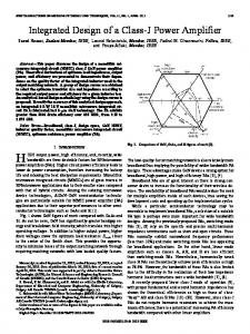
Adaptive Multi-Band Multi-Mode Power Amplifier Using Integrated Varactor-Based Tunable Matching Networks W. C. Edmund Neo, Student Member, IEEE, Yu Lin, Xiao-dong Liu, Leo C. N. de Vreede, Senior Member, IEEE, Lawrence E. Larson, Fellow, IEEE, Marco Spirito, Student Member, IEEE, Marco J. Pelk, Koen Buisman, Student Member, IEEE, Atef Akhnoukh, Anton de Graauw, and Lis K. Nanver, Member, IEEE
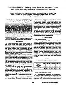
Abstract—This paper presents a multi-band multi-mode class-AB power amplifier, which utilizes continuously tunable input and output matching networks integrated in a low-loss silicon-on-glass technology. The tunable matching networks 100 @ 2 GHz) make use of very high Q varactor diodes (Q in a low distortion anti-series configuration to achieve the desired source and load impedance tunability. A QUBIC4G (SiGe, = 50 GHz) high voltage breakdown transistor ( CBO = 14 V, 3 6 V) is used as active device. The realized adaptive CEO amplifier provides 13 dB gain, 27–28 dBm output power at the 900, 1800, 1900 and 2100 MHz bands. For the communication bands above 1 GHz optimum load adaptation is facilitated resulting in efficiencies between 30%–55% over a 10 dB output power control range. The total chip area (including matching networks) of the amplifier is 8 mm2 . Index Terms—Adaptive matching network, dynamic loadline, high efficiency, multi-band, multi-mode, power amplifier, RF adaptivity.
I. INTRODUCTION N ORDER TO fulfill the multi-band, multi-mode demands of today’s cellular market, current handset implementations are based on parallel line-ups for the transmit and receive paths [Fig. 1(a)] with antenna duplexers and switches to meet the specific requirements of each communication standard. Next-generation wireless systems aim for size and cost reduction by utilizing only one or two adaptive transmit/receive paths to replace the parallel path concept [Fig. 1(b)]. Although conceptually simple, practical design considerations place severe design constraints and technology challenges on the adaptive circuit blocks required. For most of the circuit functions in the receive path, acceptable implementations have already been demonstrated [1]–[3]. Major challenges remain, however, in creating the tunable filters and adaptive power amplifiers (PAs) [4], [5]. To address these challenges we focus in this paper on
I
Manuscript received January 6, 2006; revised May 10, 2006. This work was supported in part by Philips Semiconductors, Philips Research, and the Dutch Technology Foundation (STW). W. C. E. Neo, Y. Lin, X.-D. Liu, L. C. N. de Vreede, M. Spirito, M. J. Pelk, K. Buisman, A. Akhnoukh, and L. K. Nanver are with the DIMES Institute, Delft University of Technology, 2628 CT, Delft, The Netherlands. L. E. Larson is with the University of California at San Diego, La Jolla, CA 92093 USA. A. de Graauw is with Philips Semiconductors, 6534 AE Nijmegen, The Netherlands. Digital Object Identifier 10.1109/JSSC.2006.880586
the implementation of an adaptive PA. Our aim is to improve the power-added efficiency (PAE) and provide adaptation of the operating frequency. A. PA Requirements The power amplifier stage in a mobile handset is considered to be one of the most power hungry components. As a result, the talk-time of a typical handset is restricted to several hours by the limited PA efficiency and battery performance. There are two basic constraints for a mobile system that are responsible for this limitation: • the maximum output power required, related to transmitted power, when the handset is operated at a large distance from the base-station; • the high linearity requirement of a modern wireless communication system, which translates to a power back-off condition of several dB for the output stage. In traditional amplifier implementations, the linearity requirement typically results in the use of class-AB operation for the output stage [6], which provides a workable compromise between linearity and efficiency. When considering linearity, the class-AB output stage must be dimensioned in such a way that it can provide its peak output power without saturation. As a re) and battery voltage sult, for a given peak output power ( ( ), the load impedance for a class-AB stage at the funda. mental frequency is fixed to Unfortunately, class-AB operation provides its highest efficiency only under maximum drive conditions. When operated at the required back-off level, due to linearity reasons for a given communication standard like (W)CDMA, a rather dramatic loss in efficiency occurs [7]. It is for these reasons that improving amplifier efficiency, while maintaining linearity, is currently a major research topic in wireless communications. In linearity-focused research, the circuit is designed so that the resulting overall linearity performance of the PA module is improved. In this way, the active device can be operated closer to its peak-power capabilities and still be able to meet the linearity requirements. Pre-distortion is one technique that falls in this category. In pre-distortion (analog or digital) [8], the input signal is adjusted such that it compensates for the nonlinearities of the PA stage. Another increasingly utilized linearization technique is that of out-of-band termination [9]; here the impedances at baseband and second harmonic frequencies are
0018-9200/$20.00 © 2006 IEEE
NEO et al.: ADAPTIVE MULTI-BAND MULTI-MODE POWER AMPLIFIER USING INTEGRATED VARACTOR-BASED TUNABLE MATCHING NETWORKS
Fig. 1. (a) Traditional parallel path multi-band multi-mode approach based on static RF circuit blocks. (b) Simplified next-generation transceiver concept based on adaptive RF function blocks.
carefully tailored such that, through secondary mixing, the IM3 components resulting from third-order nonlinearities are cancelled. Although these techniques have proven to be effective, they do not improve the efficiency when the PA is operated at large power back-off levels. Techniques that address the efficiency in the back-off mode are dynamic biasing [10] or regulation of the supply voltage of the output stage [11]. Dynamic biasing provides only modest improvements in efficiency, and supply voltage regulation requires an efficient DC-to-DC conversion, increasing system cost and complexity. An alternative for improved class-AB efficiency is load-line adjustment as a function of output power using an adaptive or reconfigurable output matching network. Typically, such a network is based on PIN-diode or PHEMT switching of matching elements like inductors, transmission-lines [5] or capacitors. In addition, MEMS capacitors are currently being considered for this application although they still have manufacturing and reliability issues and, when continuously tunable, linearity constraints [4], [12]–[16]. To overcome the limitations of existing adaptive matching solutions we aim to use varactor diodes for the continuous tuning of the characteristics of the matching network. Unfortunately, the classical problem related to varactor diodes is their distortion when a modulated signal is applied to their terminals, disqualifying them for linear applications. In [17] and [18], however, it was demonstrated that by stacking diodes in anti-series, one can obtain an almost “distortion-free” tunable capacitor. A logical idea would be to realize these structures in conventional silicon technology. However, the series parasitics related to such a varactor implementation (e.g., the resistance of the buried layer and
2167
connecting metal fingers) would yield unworkable high losses for the intended capacitance values. This parasitics-induced limitation can be overcome by realizing the “distortion-free” varactor concept on a glass substrate transfer technology (silicon-on-glass) [19], facilitating low-ohmic contacting of the intrinsic device at both front @ GHz) and back-side, providing ultra-low loss ( tunable capacitors which exhibit almost no distortion. This, combined with the use of thick metal layers (copper plated) for the realization of high inductors and transmission lines, facilitates the integration of high quality tunable integrated matching networks [20], which are adaptive in port impedance and operating frequency. Note that these integrated adaptive networks can play an important role for the realization of the next generation of adaptive transceivers [Fig. 1(b)]. To illustrate the feasibility of this approach, we have demonstrated in [24] an 1800 MHz QUBIC4G [23] bipolar PA with adaptive integrated input and output matching networks. Using these matching networks, high-efficiency performance has been obtained even at large power back-off conditions by adapting the load that the active device sees as a function of the output power. In this paper, we take the next step and combine the high-efficiency performance of the adaptive PA for full and back-off power levels with multi-band functionality. This paper is organized as follows. In Section II, we review why we are able to achieve better power-efficiency performance at different power levels by changing the load impedance of the output stage. In Section III, we discuss the design, fabrication and characterization of the adaptive matching networks used in this work. In Section IV, we present the design of the complete PA module (active device and matching networks). The efficiency improvement for a single-tone signal as function of output power (impedance) is given at the different frequency bands to illustrate the improvement in power efficiency over a classical class-AB PA implementation. The conclusions are given in Section V. II. STATIC LOAD-LINE MODULATION CONCEPT When considering a normal class-B amplifier, the supply voltage ( ) and the load resistance ( ) are fixed quantities is set by the peak output. Since, for ideal class-B in which , when operation the max output voltage amplitude equals the device is delivering peak power, the output power can be written as (1) The maximum collector efficiency can be simply written for a sinusoidal signal as (2) Note that this expression only involves a ratio of currents and for sinusoidal signals this ratio equals , which gives the theoretical efficiency of 78.5% for class-B amplifiers. Unfortunately,
2168
IEEE JOURNAL OF SOLID-STATE CIRCUITS, VOL. 41, NO. 9, SEPTEMBER 2006
at back-off power levels the voltage swing at the collector is only . Inserting this back-off a fraction of the bias supply voltage voltage level into the efficiency equation, we obtain
(3) We observe that the efficiency drops with the square root of the power back-off ratio. However, if is changed such that the voltage swing at the collector is kept equal to the bias supply voltage, the power efficiency in (2) can be achieved at all power levels, and there is no drop in efficiency when the power is backed off. Although the considerations above apply to class-B operation, they can also be applied to class-E or class-F amplifiers, yielding a theoretical upper limit of 100% efficiency for all output power levels.
power handling range of the design. With the above constraints in mind, we aim for the following specifications for the reconfigurable matching network: • impedance transformation ratio 10; • continuously tunable with high tuning speed (20-MHz bandwidth); • operating frequencies of 900, 1800, 1900, and 2100 MHz (covering the most important bands for handsets); • losses 1 dB for the whole input impedance tuning range; • number of independent control voltages 2; • high linearity ( 55 dBc at 1 W output power level); • output power range from 0.1 to 1 W assuming a 3-V supply voltage; • improved amplifier efficiency for power back-off conditions. In order to meet these requirements, we need to determine the most promising network topology.
III. RECONFIGURABLE MATCHING NETWORK In order to effectively change the loading impedance of the output stage as a function of the desired output power level, tunable matching networks are required. In this section, we discuss the basic requirements these networks must satisfy to obtain the desired PA functionality in terms of power control range and frequency tuning. Following that, we discuss the design of the matching network within the technology constraints and the resulting implementation with its measurement results. A. Design Goal of Adaptive Matching Networks For the implementation of our tunable matching network, we use uniformly doped varactors in a silicon-on-glass technology. To improve linearity, the anti-series configuration of two uniformly doped varactors [17], [18] is used. Note that this configuration is theoretically distortion-free when a high impedance is used for biasing the center node. Compared to other RF tunable components, these elements provide superior linearity, reliability, capacitance tuning speed and quality factor ( @ GHz), making them fundamental enabling components for wireless applications [18]. The currently available varactor devices in our silicon-onglass process place the following design constraints on the reconfigurable matching network: • effective capacitance tuning range of the varactor stack ): 2.5; ( • control voltages: 18 V (to avoid diode breakdown); • no forward biasing of any of the diodes by the RF signal. Although in principle, control voltages up to 18 V are required to obtain the full capacitance tuning range for this technology version, it is noted that the varactor diodes are always operated in reverse bias and therefore require practically no current. Consequently, the generation of these control voltages by DC-to-DC up-conversion is relatively straightforward without any severe requirement on conversion efficiency. The actual value of the control voltages depends on the intended capacitance control range and the RF voltage swing present in the matching network. By using a low matching network solution in combination with low impedance levels, one can improve the
B. Choice of Adaptive Matching Network Topology Since we aim for low-loss matching network implementations with only two control voltages, we limit the number of reactive elements in our analysis to a maximum of four. The networks considered in our analysis are given in Fig. 2. Variable inductors are composed of an inductor/varactor combination with a net positive reactance. Of these networks, the -type network is the simplest. In principle this configuration can provide impedance transformation up to the loading impedance of the network (50 ). Unfortunately, to obtain an acceptable impedance transformation range, it requires a very large tuning range for its component values. A -type matching network has one more element than a -type network, which in principle allows a load termination to be transformed to any position within the Smith-chart. When using two -type matching networks in cascade, we obtain the so-called two-stage ladder matching network. As with the -type matching network, this topology allows an impedance transformation that covers the entire Smith chart. The advantage of the ladder network over the -type network is that, for higher impedance transformation of the two-stage network is significantly lower. ratios, the Note that high conditions in the matching network give rise to increased losses and higher voltage swings, limiting the power handling capabilities. When implementing a transformer or coupled line-based matching network, one suffers from the tradeoff between the impedance tuning range and coupling factor of the coils. As a result, high conditions are required to obtain the intended tuning range, yielding higher losses. All these matching phase variations ( 10 degrees over networks yield large a 5 to 50 impedance range) when changing the impedance transformationbyadjustingthenetworkelements.Whenchanged dynamically [21], [22], this phase variation appears as an AM-to-PM distortion and degrades the linearity of a dynamic load modulated amplifier when no compensating measures like digital predistortion are taken. If one wants to avoid the use of predistortion in this application, one can consider network
NEO et al.: ADAPTIVE MULTI-BAND MULTI-MODE POWER AMPLIFIER USING INTEGRATED VARACTOR-BASED TUNABLE MATCHING NETWORKS
2169
Fig. 2. Network topologies considered for the implementation of the adaptive matching network. (a) L-type network. (b) � -type network. (c) Two section L-type network. (d) Transformer coupled network. (e) Constant delay network.
TABLE I EVALUATION OF MATCHING NETWORKS
Fig. 3. Schematic diagram of the two-stage ladder network.
C. Implementation and Measurements of Adaptive Matching Networks
solutions that provide no phase variation when changing the impedance ratio. A transmission transformer is such a network [Fig. 2(e)], which, for a limited bandwidth, can be approximated by its lumped equivalent. Consequently, by simultaneously, one can vary the changing both the and characteristic impedance while keeping the phase delay constant. This approach requires tunable inductors, which in principle can be implemented using a combination of an inductor and a capacitor. However, in practice this will result in increased losses making this topology less favorable compared to the other suggested matching network solutions. The results of our analysis are summarized in Table I. Based on this table, the discussion above and the fact that we aim for static adaptive matching in this work, we have chosen the two-stage ladder network as the most suitable topology for our application. In the following section, we give the implementation details of this matching network and its measurement performance.
The schematic diagram of the two-stage ladder network is shown in Fig. 3. The tunable capacitors are composed of an anti-series configuration of two varactors, which form the so-called varactor stack (VS). A high value resistor and two diodes in anti-parallel configuration have been used to realize sufficiently high impedance for the varactor stack center tap to avoid linearity degradation for narrow tone spacing [18]. Each varactor stack is independently controlled for its effective capacitance through its center-tap voltage. The inductors can be realized either by coplanar waveguide [20] or bondwires; all reported matching networks are implemented using silicon-on-glass technology [19]. In our experiment, we used bondwires for the implementation of the inductors to facilitate tuning of the integrated matching network and simplify the connection to the active device. The values of the varactors and the inductance of the bondwires were chosen to achieve a large impedance control range at 1900 MHz and to obtain the lowest loss condition for the highest output power. The final bondwire dimensions were verified using a three-dimensional (3-D) field simulator. The layout and components values are given in Fig. 4 and Table II, respectively.
2170
IEEE JOURNAL OF SOLID-STATE CIRCUITS, VOL. 41, NO. 9, SEPTEMBER 2006
Fig. 4. Microphotograph of matching network using bondwires to realize the inductor.
TABLE II ELEMENT VALUES OF OUTPUT MATCHING NETWORK
The -parameters of the matching network were measured using a HP8510C network analyzer. Fig. 5 shows the measured of the integrated matching networks at 900, 1800, 1900, and 2100 MHz; this measurement illustrates the band-switching and impedance transformation capabilities of our adaptive matching network loaded with 50 at its output. The data of Fig. 5 is based on the on-wafer measured -parameters of the device shown in Fig. 4. With this, we obtain the data at the reference plane of the output of the active device. From Fig. 5 we coverage in the Smith chart is very large observe that the for the higher frequency bands, providing a resistive impedance transformation range much larger than 10. Although the control range for the 900 MHz band is very limited, we can still approach the matching condition for the highest intended output power of the active device (28 dBm). Note that the 28 dBm optimum loading condition indicated on the Smith Chart assumes a lossless matching network. To compensate for the losses of the actual network, a slightly lower impedance has to be offered in practice. One of the most important aspects of tuner design is to maximize the power gain ( ) or minimize the losses of the structure. The definition of this gain is (dB)
(4)
is a more appropriate measure than , Note that assumes conjugate matching conditions at both since was approximately 0.3 dB for all input and output. ( tuning values). Fig. 5 plots the measured loss contours up to 4 dB. The losses of these matching networks are caused by the limited of the inductors and the parasitic resistance of the varactor stacks. of the matching network was optimized to be low The for the high power condition in order to avoid forward biasing
G
Fig. 5. (a) Measured S and (b) contours of constant of the adaptive output matching network at 900, 1800, 1900 and 2100 MHz, the simulated optimum loading trajectories for the highest efficiency are indicated. 18 V; required control voltage for the optimum load trajectory 10 V.
V