This research was supported by DARPA/ARDC under contract No. DAAK10-83-C-0126 and p a r t i a l l y by U. S. Army. Fort. Belvoir. Research,. Development,.
ADVANCED COMPULSATOR DESIGN
By: M. D. Driga S. B. Pratap W. F. Weldon
Fourth Symposium on Electromagnetic Launch Technology, Austin, TX, April 12-14, 1988
IEEE Transactions on Magnetics, Vol. 25, no. 1, January 1989, 142-146
PR - 67
Center for Electromechanics The University of Texas at Austin PRC, Mail Code R7000 Austin, TX 78712 (512) 471-4496 ©1989 IEEE. Personal use of this material is permitted. However, permission to reprint/republish this material for advertising or promotional purposes or for creating new collective works for resale or redistribution to servers or lists, or to reuse any copyrighted component of this work in other works must be obtained from the IEEE.
142
IEEE TRANSACTIONS ON MAGNETICS, VOL. 25, NO. 1, JANUARY 1989 ADVAIX%D COU?t&SATOR DESIGN
M. D. Driga, S. B. P r a t a p , and U. F. Weldon Center f o r Electromechanics The U n i v e r s i t y of Texas at Austin Aus t i n , - TX 78758-4497 Abstract: Compulsator is a n a m e d e f i n i n g a l a r g e family of high energy pulsed power rotating machinery[l]. The compensated pulsed a l t e r n a t o r s cover an e x t e n s i v e range of c u r r e n t s , v o l t a g e s , p u l s e shapes, and a l s o frequency i n t h e case of multi-pulse generators. The compulsator embodies t h e s i n g l e element philosophy combining i n one element t h e energy s t o r a g e , electromechanical energy conversion, and t h e power conditioning. However, i n s i d e t h e machine such f u n c t i o n s a r e done i n a "staged" manner. Two examples a r e given i n t h i s paper, in o r d e r t o i l l u s t r a t e such a philosophy of design: t h e f l a t p u l s e a i r - c o r e comp u l s a t o r , and t h e high v o l t a g e two s t a g e uncompensated machine (uncompulsator) capable of reaching v o l t a g e s above 100-kV l e v e l .
r
SHORTED COMPENSATING
COMPOSITE BANDING
r FIELD COILS
Iatreductiea High energy, pulsed power supplies are i n c r e a s i n g l y required i n d i f f e r e n t a p p l i c a t i o n s such as space launching, electromagnetic countermeasure systems , and industry. The one-element power supply must combine t h e energy s t o r a g e , conversion and pulse shaping in a s i n g l e generator. I n two previous papers [ 2 , 3 ] t h e methods t o shape t h e time p r o f i l e of t h e o u t p u t c u r r e n t f o r a given e x t e r n a l impedance were r e l a t e d t o t h e v a r i a t i o n in t i m e of both, t h e induced e l e c t r o m o t i v e f o r e e and t h e i n t e r n a l impedance of t h e cornpulsator i t s e l f . F u n c t i o n a l l y t h e r e a r e two g e n e r a l methods of p u l s e shaping: t o p o l o g i c a l d i s t r i b u t i o n s of t h e a c t i v e conductors i n t h e machine and dynamic i n t e r a c t i o n s between a c t i v e conductors and between windings and s h i e l d s . The second method is a c t u a l l y a second s t a g e of t h e process, i n which t h e f i x e d d i s t r i b u t i o n s of a c t i v e and p a s s i v e conductors i n t e r a c t during t h e d i s c h a r g e , achieving compensation and f l u x compression i n s e l e c t e d a r e a s , leaving t h e f l u x unchanged in t h e rest of t h e machine, such a r e a s changing i n time a s t h e machine turns.
\ARMATURE
WINDING
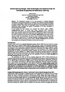
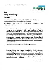
F i g u r e 1.
Plat p u l s e compulsator using s e l e c t i v e p a s s i v e compensation
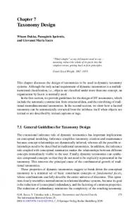
A problem a s s o c i a t e d with t h i s p a r t i c u l a r conf i g u r a t i o n is t h a t c e r t a i n s e c t i o n s of t h e compensating winding experience a r a d i a l l y inward force. It is difficult t o support t h e compensating winding under t h e r a d i a l l y inward load without compromising machine performance. T h i s problem is b e t t e r understood by c o n s i d e r i n g Figures 2 and 3. Figure 2 shows t h e c u r r e n t in t h e armature winding and compensating winding as a f u n c t i o n of t i m e . It is t o be noted t h a t t h e support s t r u c t u r e of t h e f i e l d c o i l is made of aluminum which is a good conductor. The support s t r u c t u r e a l s o s e r v e s t o exclude t h e d i s c h a r g e f i e l d s
Such an approach is i l l u s t r a t e d in t h e f i r s t d e s i g n case. I n t h e second example a p a r t of t h e g e n e r a t o r armature winding is s h o r t c i r c u i t e d , t h u s c r e a t i n g a sudden i n c r e a s e in e x c i t a t i o n a s a react i o n , and consequently a high v o l t a g e induced in t h e rest of t h e armature winding. The Flat Pulse Compulsator The f l a t p u l s e compulsator which is being designed f o r Task C of t h e armor antiarmor program is an air-cored machine. The c r o s s s e c t i o n of t h i s machine is shown in F i g u r e 1. The machine g e n e r a t e s a f l a t - t o p p e d c u r r e n t p u l s e when connected t o a r a i l g u n ( 8 m long). The machine has two p o l e s and is comprised of t h e e x c i t a t i o n f i e l d c o i l , a s i x conduct o r p e r pole, l a p wound armature winding, t h e compens a t i n g winding which is a l s o l a p wound and has 26 conductors p e r pole. The compensating winding is s h o r t e d on i t s e l f . The compensating winding with i t s a b i l i t y t o provide s e l e c t i v e dynamic f l u x compression is t h e component which enables t h e machine t o g e n e r a t e a flat-topped c u r r e n t pulse.
TIME (SEC)
F i g u r e 2.
'10-2
Current i n t h e armature and compensating winding a s a f u n c t i o n of t i m e
0018-9464/89/0100-0142$01.0001989 IEEE
©1989 IEEE. Personal use of this material is permitted. However, permission to reprint/republish this material for advertising or promotional purposes or for creating new collective works for resale or redistribution to servers or lists, or to reuse any copyrighted component of this work in other works must be obtained from the IEEE.
143
\
A
7
SUPPORT
t = O .
BOUNDARY
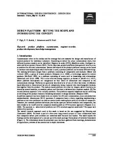
t i a t i o n of discharge. In t h i s p o s i t i o n t h e f i e l d below t h e compensating winding over t h e s e c t o r of t h e p o l e s p a c e r of t h e armature winding is predominantly r a d i a l . The f i e l d o u t s i d e t h e compensating winding is s t i l l t a n g e n t i a l and t h e r e f o r e t h i s s e c t o r sees a r a d i a l l y inward f o r c e . F i g u r e 5 shows t h e f o r c e d i s t r i b u t i o n a s a f u n c t i o n of a n g u l a r l o c a t i o n . 0 0 0
0
I 0 n
0 0 d.
ARMATURE^
COMPENSATING WINDING
WINDING
0
- c 8y
*
-rn
h
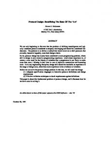
F i g u r e 3.
Rotor p o s i t i o n a t 800 Us
5 0 W
K
3
from t h e region of t h e f i e l d c o i l . T h i s second funct i o n of t h e support s t r u c t u r e a l s o i m p l i e s t h a t t h e r e is a s i g n i f i c a n t t a n g e n t i a l component of t h e d i s c h a r g e magnetic f i e l d s between t h e compensating winding and This is t h e s o u r c e of a t h e support s t r u c t u r e . r a d i a l l y inward f o r c e on t h e compensating winding. F i g u r e 3 shows t h e r o t o r p o s i t i o n a t 800 PS from t h e i n i t i a t i o n of discharge. A t t h i s i n s t a n t t h e armature is in t h e minimum inductance p o s i t i o n . The magnetic f i e l d between t h e armature and compensating winding h a s a t a n g e n t i a l component which is h i g h e r than t h e t a n g e n t i a l component between t h e compensating winding and support s t r u c t u r e , t h e r e f o r e t h e r a d i a l f o r c e on t h e compensating winding is e n t i r e l y outward. F i g u r e 4 shows t h e r o t o r p o s i t i o n a t 1.5 ms from t h e i n i -
.
SUPPORT STRUCTURE BOUNDARY
rn rno w Q K
n
0
P 0
? 0 0
?
80
160
240
I
I
I
320
400
480
DEGREES
F i g u r e 5.
Radial f o r c e d i s t r i b u t i o n on compensating winding a t 1.5 m s
There a r e two methods of overcoming t h i s problem, one mechanical and t h e second e l e c t r i c a l in n a t u r e . The f i r s t method i s t o u s e an e x t e r n a l r o t o r This c o n f i g u r a t i o n c o n f i g u r a t i o n shown in F i g u r e 6 . p l a c e s t h e banding on t h e armature winding r a d i a l l y outward. The compensating winding can now be banded w i t h high s t r e n g t h composite m a t e r i a l t o p r o t e c t i t from t h e r a d i a l l y outward e l e c t r o m a g n e t i c f o r c e s , thus m a i n t a i n i n g t h e coupling between t h e armature and c o w p e n s a t i n g winding t h e same a s i n t h e c a s e of the i n t e r n a l r o t o r machine.
ARMATURE-/ WINDING
F i g u r e 4.
’
\ -
COMPENSATING WINDING
Rotor p o s i t i o n a t 1.5 ms
The second s o l u t i o n is t o make t h e compensating winding o u t of s h o r t e d s i n g l e t u r n s r a t h e r than a l a p wound continuous wire. This c o n f i g u r a t i o n removes t h e c o n s t r a i n t t h a t t h e same compensating c u r r e n t must p a s s through each t u r n of t h e compensating winding. The c u r r e n t on each of t h e s e t u r n s now f o l l o w s a d i f f e r e n t p r o f i l e w i t h time t h u s i n t r o d u c i n g s e v e r a l d e g r e e s of freedom. F i g u r e 7 shows t h e c u r r e n t i n t h e armature windlng and a l s o t h e c u r r e n t in t h e v a r i o u s shorted The c u r r e n t in t h e compencompensating conductors.
©1989 IEEE. Personal use of this material is permitted. However, permission to reprint/republish this material for advertising or promotional purposes or for creating new collective works for resale or redistribution to servers or lists, or to reuse any copyrighted component of this work in other works must be obtained from the IEEE.
ROTOR
-
r ARMATURE WINDING COMPENSiATING WINDING
-FIELD
COIL
. %-
0
F
BANDING
w F i g u r e 6.
wa
E x t e r n a l r o t o r machine
0
TO
80
160
240
320
400
%
480
DEGREES
F i g u r e 8.
TIME (SEC)
Radial f o r c e d i s t r i b u t i o n
'10-2
I
F i g u r e 7.
Current i n t h e armature winding and v a r i o u s compensating conductors
s a t i n g t u r n s c l o s e s t t o t h e p o l e s p a c e r have t h e short e s t p u l s e width and t h i s p u l s e width i n c r e a s e s f o r conductors f u r t h e r away from t h e p o l e s s p a c e r . This v a r i a t i o n in p u l s e width is in accordance t o t h e v a r i a t i o n of t h e mutual c o u p l i n g of t h e compensating t u r n s w i t h t h e armature windings. Since the pulse w i d t h of t h e compensating c u r r e n t s c l o s e s t t o p o l e s p a c e r is reduced, t h e c u r r e n t in t h e s e conductors is s i g n i f i c a n t l y lower when t h e p o l e s p a c e r of t h e armat u r e winding is a l i g n e d w i t h them t h u s reducing t h e r a d i a l l y inward f o r c e s . F i g u r e 8 shows t h e r a d i a l f o r c e d i s t r i b u t i o n in t h e compensating winding u s i n g s h o r t e d s i n g l e t u r n s f o r t h e r o t o r p o s i t i o n shown i n F i g u r e 4.
I 82 y2
I
OUTPUT TERMINAL CONNECTIONS xz
F i g u r e 9.
Schematic of t h e h i g h voltage generator
Rigb Voltage Generator
o f s h i e l d i n g , u s i n g f i n e l y laminated f e r r o m a g n e t i c materials or making u s e of h i g h s t r e n g t h , h i g h s t i f f n e s s , low d e n s i t y composite materials such a s epoxy impregnated g r a p h i t e , g l a s s , or boron f i b e r s .
The h i g h v o l t a g e g e n e r a t o r , s c h e m a t i c a l l y repres e n t e d in F i g u r e 9 , is t e c h n i c a l l y t h e e l e c t r o m a g n e t i c d u a l of a compulsator. Unlike t h e compulsator, which u s e s a n a c t i v e or p a s s i v e compensating winding, t h i s machine h a s a laminated s t r u c t u r e and a v o i d s any means
The o p e r a t i o n is based on t h e " c o n s t a n t f l u x l i n k a g e p r i n c i p l e " f o r s h o r t c i r c u i t s in synchronous machines. The magnetic f l u x is trapped and t h e magnet i c l i n k a g e of e a c h winding m s t remain c o n e t a n t a t t h e l e v e l i t had a t t h e i n s t a n t of s h o r t c i r c u i t . I f , however, o n l y two phases ( o u t of t h r e e ) are s h o r t c i r -
©1989 IEEE. Personal use of this material is permitted. However, permission to reprint/republish this material for advertising or promotional purposes or for creating new collective works for resale or redistribution to servers or lists, or to reuse any copyrighted component of this work in other works must be obtained from the IEEE.
145
c u i t e d , t h e t h i r d phase w i l l produce a l a r g e v o l t a g e many times i t s r a t e d v o l t a g e . The two s h o r t - c i r c u i t e d phases form a winding whose a x i s i s p e r p e n d i c u l a r t o t h e a x i s of t h e t h i r d ( o u t p u t ) phase ( F i g u r e 10). When t h e s w i t c h S is c l o s e d , t h e two phases, B and C, a r e s h o r t c i r c u i t e d and t h e event i s s i m i l a r t o t h e sudden s h o r t c i r c u i t The f l u x e s , of a conventional synchronous machine. c u r r e n t s , and e l e c t r o m o t i v e f o r c e s add v e c t o r i a l l y f o r t h e two phases. T h e i r r e s u l t i n g phasor makes an a n g l e of 90' w i t h t h e corresponding one f o r phase A ( f i g . 1l a ) .
f l u x , @2 can be d i v i d e d i n t o u s e f u l f l u x (+zU) and . f o r s i m p l i c i t y t h a t the l e a k a g e f l u x ( 9 ~ ~ ) Assuming primary and t h e secondary number of t u r n s a r e equal--i.e., t h e r e s p e c t i v e primary and secondary usef u l inductances a r e equal, = Lu2 = Lu. Then, 02 =
+
@2a= (L,
-
+
+
LJI
a2)iex (1)
A f t e r t h e r o t o r h a s turned w i t h an a n g l e a, a f t e r a t i m e interval: t = a/w
The e q u a t i o n s f o r t h e f l u x l i n k i n g t h e primary and secondary windings become:
where 11, 1 2
F i g u r e 10.
D i s p o s i t i o n of t h e phase windings ( e l e c t r i c angle)
t h e instantaneous values f o r c u r r e n t s i n t h e s t a t o r and rotor, respectively L l a , L2a and h = t h e leakage inductances f o r primary, secondary, and respect i v e l y f o r t h e common f l u x 01, 02 = l e a k a g e c o e f f i c i e n t s =
Using r e l a t i o n ( 1 ) w e a r r i v e a t much s i m p l e r e q u a t i o n s (1 + a 1 ) i l + 12 s i n a = 0 ( 1 + 02112 + i l s i n a = ( 1
-
------.)-
BC
1
(AS PHASORS K B )
= 1
+ a1
MMF, PHASE A
+
(1
+
U,)(l 1
(I,) L
2
cos a 1 ( 1 + u p 1 + a2)
e-
2
-
L
1
- E+
-
a1
a2 f
a
ex
cos
L
cos a
+
The v a l u e s become c r i t i c a l f o r c o s a t h e s h o r t c i r c u i t . These v a l u e s a r e
i cr = 2 -
a2)iex
cosa
1 l2 =
+
ex
+ a
a2) =
-1,
180" a f t e r
i ?,ex a + a 1
2
,
F i g u r e l l a and l l b .
Phasorial relationships between phase windings
The s h o r t c i r c u i t of phases I3 and C i n series can b e considered a s a s i n g l e phase in t h e d i r e c t i o n of t h e r e s u l t a n t phasor ( f i g . I l b ) . If the short circ u i t occurs i n t h e moment i n which no f l u x of e x c i t a t i o n i s l i n k i n g t h e s h o r t e d armature w i n d i n g s - w e have t h e f i r s t c h a r a c t e r i s t i c p o s i t i o n ; i f i t occurs i n t h e moment i n which t h e maximum e x c i t a t i o n f l u x l i n k s t h e s h o r t e d armature w i n d i n g s - r e have t h e second c h a r a c t e r i s t i c position. The e x c i t a t i o n (secondary)
The r e s u l t a n t f l u x in t h e c r i t i c a l moment i s produced by t h e e x c i t a t i o n , on t h e r o t o r and f o r c o s a = -1 ( a = 180').
a l - a =
'u(a1
ar
=
+
2 u2
+ a a
+
1 2 ola2)iex
o ( a f t e r 180')
©1989 IEEE. Personal use of this material is permitted. However, permission to reprint/republish this material for advertising or promotional purposes or for creating new collective works for resale or redistribution to servers or lists, or to reuse any copyrighted component of this work in other works must be obtained from the IEEE.
146
Table The p h y s i c a l p i c t u r e corresponding t o t h e f l u x and c u r r e n t r e l a t i o n s o b t a i n e d above is: 1.
2.
For t h e f i r s t c h a r a c t e r i s t i c p o s i t i o n - - t h e armaThe t u r e is w i t h o u t c u r r e n t and l i n k s no f l u x . r e s u l t a n t f l u x produced is h a l f of t h e non-load f l u x , t h e o t h e r h a l f is produced by t h e e x c i t a t i o n i n c o n j u n c t i o n w i t h t h e armature winding, a l o n g t h e a i r g a p such t h a t two h a l v e s compensate i n t h e armature and add i n t h e e x c i t a t i o n member ( i n our case rotor). For t h e second c h a r a c t e r i s t i c p o s i t i o n , the armature i s a t full c u r r e n t and l i n k s maximum f l u x , t h e two windings t r y i n g t o m a i n t a i n t h e f l u x constant. S i n c e a f t e r 180" ( h a l f p e r i o d ) t h e two f l u x e s have o p p o s i t e d i r e c t i o n s t h e y t e n d t o compensate each o t h e r . The r e s u l t i n g f l u x is almost z e r o , so t h e two windings nust produce t h e whole no-load f l u x a l o n g t h e a i r g a p path.
&e second s t a g e of t h e system i n v o l v e s producing As t h e h i g h v o l t a g e i n t h e t h i r d phase winding AA'. shown i n f i g u r e s 10 and 11, t h e two s h o r t c i r c u i t e d phases form a winding whose a x i s is p e r p e n d i c u l a r t o t h e a x i s of t h e h i g h v o l t a g e winding AA', and, cons e q u e n t l y t h e y cannot induce t h e h i g h v o l t a g e , being magnetically independent (decoupled). Only t h e c u r r e n t in t h e e x c i t a t i o n winding (which i s on t h e r o t o r in our c a s e ) can induce t h e high v o l t a g e . The r o t o r e x c i t a t i o n c u r r e n t a t t a i n s i t s maximum v a l u e a f t e r 90' i n t h e f i r s t c h a r a c t e r i s t i c p o s i t i o n and a f t e r 180" i n t h e second c h a r a c t e r i s t i c p o s i t i o n . The maximum i n s t a n t a n e o u s emf i n phase AA' w i l l be reached i n t h e s e p a r t i c u l a r moments [ 9 0 ° ( I ) ] and [ 1 8 0 ° ( I I ) ] and t h e i r v a l u e s are:
(3) f o r z e r o f l u x l i n k a g e a t t h e moment of t h e s h o r t c i r c u i t and
Vf = v o l t a g e , maximum v a l u e induced i n t h e o u t p u t phase, V s t e a d y - s t a t e , r o o t mean s q u a r e (rms) v a l u e of t h e phase v o l t a g e o f t h e machine, and r a t i o between t h e l e a k a g e f l u x ( s l o t , @a a = = end t u r n s , e t c . ) and t h e t o t a l f l u x @a @U ( l e a k a g e and u s e f u l ) .
-
Air c o r e h i g h v o l t a g e pulsed g e n e r a t o r (uncompensated)
Paramet e r a
Units
P
Rotor d i a m e t e r Rotor l e n g t h Rotor speed Peripheral velocity Number of p o l e s Frequency Voltage (steady s t a t e , maximm v a l u e ) Voltage output (reduced e x c i t a t i o n ) Voltage o u t p u t ( f u l l excitation) Voltage m u l t i p l i c a t i o n factor Leakage c o e f f i c i e n t Moment of i n e r t i a Energy s t o r e d a t peak velocity
Value
-
0.254 (10 i n . ) 0.1524 ( 6 in.) 33,000 439 2 550 10 118 145 14.5 (max. 15.6) 0.12 (12%) 0.249 1.49
T h i s r e s e a r c h was supported by DARPA/ARDC under and p a r t i a l l y by U. S. c o n t r a c t No. DAAK10-83-C-0126 Army Fort Belvoir Research, Development, and E n g i n e e r i n g C e n t e r under c o n t r a c t No. DM-87-P-3597.
Ufereaces
[ l l U. F. Weldon, M. D. Driga, and
H.
"Compensated Pulsed A l t e r n a t o r , " U.S. 4,200,831/April 29, 1980.
A. Woodson, P a t e n t No.
21
U. D. Driga, S. B. P r a t a p , and W. F. Weldon, "Design of Compensated Pulsed A l t e r n a t o r s w i t h IEEE Pulsed Current Waveform Flexibility," DC, J u n e 28Power Conference, Washington, J u l y 1, 1987
I31
S. B. P r a t a p , M. D. Driga, and W. F. Weldon, "Future Trends for Compulsators Driving Railguns," I E E E T r a n s a c t i o n s on Magnetics, Vol. MAG 22, NO. 6/Nov. 86, pp. 1681-1683.
(4) f o r t h e maximum i n i t i a l f l u x l i n k a g e where
.
-
T a b l e 1 shows t h e c h a r a c t e r i s t i c s f o r a d e s i g n of such a h i g h v o l t a g e , uncompensated pulsed g e n e r a t o r .
©1989 IEEE. Personal use of this material is permitted. However, permission to reprint/republish this material for advertising or promotional purposes or for creating new collective works for resale or redistribution to servers or lists, or to reuse any copyrighted component of this work in other works must be obtained from the IEEE.