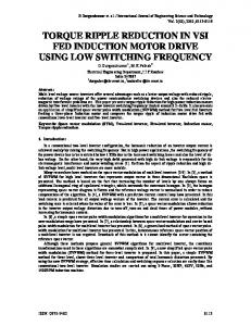
Fig. 3.6. A power electronic converter with higher demagnetization voltage. ...... bootstrap circuit without predefined inductance parameters,â IEEE Trans. Power.
ADVANCED CONTROL METHODS FOR TORQUE RIPPLE REDUCTION AND PERFORMANCE IMPROVEMENT IN SWITCHED RELUCTANCE MOTOR DRIVES
ADVANCED CONTROL METHODS FOR TORQUE RIPPLE REDUCTION AND PERFORMANCE IMPROVEMENT IN SWITCHED RELUCTANCE MOTOR DRIVES
By Jin Ye, M.A.Sc, B.Eng.
A Thesis Submitted to the Department of Electrical and Computer Engineering and the School of Graduate Studies of McMaster University in Partial Fulfillment of the Requirements for the Degree of Doctor of Philosophy
© Copyright by Jin Ye, Sep. 2014 All Rights Reserved
Doctor of Philosophy (2014) (Electrical and Computer Engineering)
McMaster University Hamilton, Ontario
TITLE:
Advanced Control Methods for Torque Ripple Reduction and Performance Improvement in Switched Reluctance Motor Drives
AUTHOR:
Jin Ye M. A. Sc., (Electrical Engineering) B. Eng. (Electrical Engineering) Xi’an Jiaotong University, Xi’an, China
ADVISOR:
Ali Emadi, Professor Ph. D. IEEE Fellow Canada Excellence Research Chair (CERC) in Hybrid Powertrain Program
NUMBER OF PAGES: XIX, 254
To My Dad, Zunyan Ye, My Mom, Rong Tang, My Husband, Haizhong Ye
ABSTRACT In this thesis, advanced control methods are presented for torque ripple reduction and performance improvement in switched reluctance motor (SRM) drives. Firstly, a comparative evaluation of power electronic converters including asymmetric, N+1, C dump, split AC, and split DC converters is presented for three-phase SRMs in terms of cost, efficiency and control performance. Secondly, two methods are proposed using torque sharing function (TSF) concepts for torque ripple reduction of SRM over a wide speed range. An offline TSF is proposed to minimize the copper loss and the absolute rate of change of flux linkage (ARCFL) with a Tikhonov factor. Then an online TSF is proposed by adding a proportional and integral compensator with torque error to torque reference of the phase with lower ARCFL. Therefore, the total torque of online TSF is determined by the phase with lower ARCFL rather than the phase with higher ARCFL as in conventional TSFs. The maximum torque-ripple-free speed (TRFS) of the offline TSF and online TSF is validated to be 7 times and 10 times as high as the best case in these conventional TSFs, respectively. Thirdly, two methods are proposed to eliminate mutual flux effect on rotor position estimation of SRM drives without a prior knowledge of mutual flux, one is the variable-hysteresis-band current control for the incoming-phase self-inductance estimation and the other is variable-sampling outgoing-phase self-inductance estimation. Compared with the conventional method which neglects the mutual flux effect, the v
proposed position estimation method demonstrates an improvement in position estimation accuracy by 2º. Fourthly, a fixed-switching-frequency integral sliding mode current controller for SRM drives is presented, which demonstrates high dynamics, strong robustness and none steady-state error. All the proposed control methods are verified by both simulations and experiments with a 2.3 kW, 6000 rpm, three-phase 12/8 SRM operating in both linear magnetic and saturated magnetic regions.
vi
ACKNOWLEDGEMENTS I would like to express my sincere gratitude to my advisor Dr. Ali Emadi for his continued invaluable advice, support, and encouragement throughout my three years’ PHD work. He is an enthusiastic and creative person to work with. Thanks to him I could successfully finish my PHD within three years. Special thanks must go to Dr. Pawel and Dr. Berker for their advice and support in my research and publications. I also would like to thank all my colleagues in McMaster Institute for Automotive Research and Technology (MacAUTO) for their accompaniment and concerns. Especially I would like to thank Hao Ge and Rong Yang for their contributions in my experimental setup of the motor drives. I owe my loving thanks to my parents for their endless support and generous love through my entire life. They have sacrificed a lot for my study abroad. Without their love and encouragement, I will never be so grateful and persistent. Especially, I express my deepest love and gratitude for my husband, Haizhong Ye for his numerous support and comfort. Thanks for being with me all the time no matter where we were and where we will be. Through so many years we spent together, I enjoy wandering, travelling, and getting older with you.
vii
CONTENTS ABSTRACT ........................................................................................................................ v ACKNOWLEDGEMENTS .............................................................................................. vii CONTENTS .................................................................................................................... viii LIST OF FIGURES .......................................................................................................... xii LIST OF TABLES ............................................................................................................xix Chapter 1
INTRODUCTION ......................................................................................... 1
1.1
Motivation ............................................................................................................. 1
1.2
Contributions ....................................................................................................... 10
1.3
Outline of the Thesis ........................................................................................... 11
Chapter 2
FUNDAMENTALS OF SWITCHED RELUCTANCE MACHINE .......... 15
2.1
Equivalent Circuit Modeling of Switched Reluctance Machine ......................... 15
2.2
Finite Element Analysis of 6/4 and 6/10 SRMs .................................................. 18
2.3
Analysis of Mutual Flux of 12/8 SRM ................................................................ 22
2.4
Torque Profiles of 12/8 SRM Considering Magnetic Saturation ........................ 26
Chapter 3
POWER ELECTRONIC CONVERTERS FOR THREE-PHASE
SWITCHED RELUCTANCE MACHINE ........................................................................ 29 3.1
Introduction ......................................................................................................... 29
3.2 Comparison of Asymmetric and N+1 Power Electronic Converters for 6/4 and 6/10 SRMs ..................................................................................................................... 36 3.2.1
Comparison with the Asymmetric Power Electronic Converter .................. 39
3.2.2
Comparisons with the N+1 Power Electronic Converter ............................. 45
3.2.3
Conclusions .................................................................................................. 50
3.3
Comparison of Power Electronic Converters for Three-Phase SRMs ................ 51
3.3.1
Comparison of Power Electronic Converters for Three-Phase SRMs ......... 51
3.3.2 Comparison of Control Performance of Power Electronic Converters through a Simulated 12/8 SRM.................................................................................. 59 3.3.3 Chapter 4
Conclusions .................................................................................................. 62 AN OFFLINE TORQUE SHARING FUNCTION FOR TORQUE RIPPLE
REDUCTION IN SWITCHED RELUCTANCE MOTOR DRIVES ............................... 64 viii
4.1
Introduction ......................................................................................................... 64
4.2
Torque Sharing Function ..................................................................................... 67
4.2.1
Conventional Torque Sharing Functions (TSFs) ......................................... 67
4.2.2
Evaluation Criteria of TSF ........................................................................... 69
4.3
The Proposed Offline Torque Sharing Function ................................................. 70
4.3.1
Derivation of Offline Torque Sharing Functions (TSFs) ............................. 70
4.3.2
Selection Guide of Tikhonov Factors .......................................................... 76
4.3.3
Comparison between Conventional TSFs and Proposed Offline TSFs ....... 82
4.4
Simulation Verification ....................................................................................... 84
4.4.1
Simulation Results with Lower Sampling Time .......................................... 86
4.4.2
Simulation Results with Higher Sampling Time ......................................... 96
4.4.3
Comparison of Torque Ripple and RMS Current ...................................... 101
4.5
Experimental Verification ................................................................................. 107
4.6
Conclusions ....................................................................................................... 113
Chapter 5
AN ONLINE TORQUE SHARING FUNCTION FOR TORQUE RIPPLE
REDUCTION IN SWITCHED RELUCTANCE MOTOR DRIVES ............................. 115 5.1
Introduction ....................................................................................................... 115
5.2
Proposed Online Torque Sharing Function ....................................................... 117
5.2.1
Comparison of Rate of Change of Flux Linkages of Conventional TSFs . 117
5.2.2
Proposed Online TSF ................................................................................. 119
5.2.3
Comparison between Conventional TSFs and Proposed Online TSF ....... 126
5.3
Simulation Verification ..................................................................................... 128
5.3.1
Simulation Results with Lower Sampling Time ........................................ 130
5.3.2
Simulation Results with Higher Sampling Time ....................................... 140
5.3.3
Comparison of Torque Ripple and RMS Current ...................................... 146
5.4
Experimental Verification ................................................................................. 152
5.5
Conclusions ....................................................................................................... 158
Chapter 6
ELIMINATION OF MUTUAL FLUX EFFECT ON ROTOR POSITION
ESTIMATION OF SWITCHED RELUCTANCE MACHINE ...................................... 160 6.1
Introduction ....................................................................................................... 160
6.2
Error Analysis of Self-Inductance Estimation due to Mutual Flux ................... 165
6.2.1
Self-Inductance Estimation without Considering the Mutual Flux ........... 165 ix
6.2.2 6.3
Analysis of Self-Inductance Estimation Error due to Mutual Flux ........... 167
The Proposed Self-Inductance Estimation to Eliminate Mutual Flux Effect .... 173
6.3.1 Variable-current-hysteresis-band Control for Incoming-Phase SelfInductance Estimation .............................................................................................. 174 6.3.2
Variable-sampling Scheme for Outgoing-Phase Inductance Estimation ... 179
6.4
Rotor Position Estimation at Rotating Shaft Conditions ................................... 181
6.5
Simulation Verification ..................................................................................... 185
6.5.1
Simulation Results at 1200 rpm with 0.375 Nm Torque Reference .......... 187
6.5.2
Simulation Results at 4500 rpm with 0.375 Nm Torque Reference .......... 191
6.5.3
Simulation Results at 6000 rpm with 0.2 Nm Torque Reference .............. 192
6.6
Experimental Verification ................................................................................. 193
6.6.1
Experimental Results at 4500 rpm with 0.375 Nm Torque Reference ...... 194
6.6.2
Experimental Results at 6000 rpm with 0.2 Nm Torque Reference .......... 196
6.7
Conclusions ....................................................................................................... 197
Chapter 7
A FIXED SWITCHING FREQUENCY SLIDING MODE CURRENT
CONTROLLER WITH INTEGRAL SWITCHING SURFACE FOR SWITCHED RELUCTANCE MACHINE ........................................................................................... 199 7.1
Introduction ....................................................................................................... 199
7.2
Design of Sliding Mode Current Controller ...................................................... 201
7.3
Stability Analysis of the Sliding Mode Current Controller ............................... 204
7.3.1 Stability Analysis of the Sliding Mode Controller Neglecting the Modeling Error of Motor Parameters ....................................................................................... 204 7.3.2 Stability Analysis of the Sliding Mode Controller Considering the Modeling Error of Motor Parameters ....................................................................................... 207 7.4
Parameter Selection of Sliding Mode Controller .............................................. 213
7.5
Comparison of Sliding Mode Controller and Hysteresis Controller ................. 220
7.6
Simulation Verification ..................................................................................... 223
7.6.1
Simulation Results at 1500 rpm with 1.5 Nm Torque Reference .............. 224
7.6.2
Simulation Results at 4000 rpm with 3 Nm Torque Reference ................. 227
7.6.3
Comparison of Sliding Mode Controller and Hysteresis Controller.......... 229
7.7
Experimental Verification ................................................................................. 232
7.7.1
Experimental Results at 1500 rpm with 1.5 Nm Torque Reference .......... 232
7.7.2
Experimental Results at 4000 rpm with 3 Nm Torque Reference ............. 234 x
7.8
Conclusions ....................................................................................................... 235
Chapter 8
CONCLUSIONS........................................................................................ 236
REFERENCES ................................................................................................................ 240
xi
LIST OF FIGURES Fig. 1.1. Illustration of direct torque control of SRM. ......................................................... 2 Fig. 1.2. Illustration of indirect average torque control of SRM. ........................................ 4 Fig. 1.3. Illustration of indirect instantaneous torque control of SRM. ............................... 4 Fig. 2.1. Cross section view of 6/4 and 6/10 SRMs. (a) 6/4 SRM. (b) 6/10 SRM............. 19 Fig. 2.2. The FEA inductance profiles of 6/4 and 6/10 SRMs. (a) 6/4 SRM. (b) 6/10 SRM. .................................................................................................................................... 20 Fig. 2.3. The FEA torque profiles of 6/4 and 6/10 SRMs. (a) 6/4 SRM. (b) 6/10 SRM. .. 21 Fig. 2.4. Cross section view of 12/8 SRM. ........................................................................ 22 Fig. 2.5. The FEA inductance and torque profiles of 12/8 SRM. (a) Inductance profiles. (b) Torque profiles. .................................................................................................... 23 Fig. 2.6. Magnetic flux density of 12/8 SRM. (a) Single phase excitation. (b) Two phase excitation during phase commutation. ....................................................................... 24 Fig. 2.7. Relationship between mutual and self-inductance of the 12/8 SRM.(a) Mutual Inductance. (b) Self-inductance. ................................................................................ 26 Fig. 2.8. Comparison of calculated and FEA torque profile. ............................................. 27 Fig. 2.9. Comparison of FEA and measured torque profile. .............................................. 28 Fig. 3.1. Asymmetric power electronic converter. ............................................................. 30 Fig. 3.2. N+1 power electronic converter. ......................................................................... 30 Fig. 3.3. Power electronic converters for SRMs with even number of phases. ................. 31 Fig. 3.4. Split DC and Split AC power electronic converters for SRM. (a) Split DC Converter. (b) Split AC Converter. ............................................................................ 32 Fig. 3.5. C dump converters. (a) Conventional C dump converter. (b) Free-wheeling C dump converter. ......................................................................................................... 33 Fig. 3.6. A power electronic converter with higher demagnetization voltage. .................. 34 Fig. 3.7. Conduction angles for SRMs in one revolution. (a) 6/4 SRM. (b) 6/10 SRM. ... 38 Fig. 3.8. Block diagram of the simulation model of switched reluctance machine. .......... 39
xii
Fig. 3.9. Simulation results of 6/4 SRM for the constant current excitation with asymmetric power electronic converter. .................................................................... 40 Fig. 3.10. Simulation results of 6/10 SRM for the constant current excitation with asymmetric power electronic converter. .................................................................... 40 Fig. 3.11. Simulation results of 6/4 SRM for the constant speed operation with same controller dynamics with asymmetric power electronic converter. ........................... 42 Fig. 3.12. Simulation results of 6/10 SRM for the constant speed operation with same controller dynamics with asymmetric power electronic converter. ........................... 42 Fig. 3.13. Simulation results of 6/4 SRM for the constant speed operation with same transient response time with asymmetric power electronic converter. ...................... 44 Fig. 3.14. Simulation results of 6/10 SRM for the constant speed operation with same transient response time with asymmetric power electronic converter. ...................... 44 Fig. 3.15. Simulation results of 6/4 SRM for the constant current excitation with N+1 converter. ................................................................................................................... 46 Fig. 3.16. Simulation results of 6/10 SRM for the constant current excitation with N+1 converter. ................................................................................................................... 46 Fig. 3.17. Simulation results of 6/4 SRM for the constant speed operation with same transient response time with N+1 converter............................................................... 48 Fig. 3.18. Simulation results of 6/10 SRM for the constant speed operation with same transient response time with N+1 converter............................................................... 49 Fig. 3.19. Five modes of the C dump converter. ................................................................ 55 Fig. 3.20. Comparison of torque ripple. ............................................................................. 61 Fig. 3.21. Comparison of average torque. .......................................................................... 62 Fig. 3.22. Comparison of RMS current.............................................................................. 62 Fig. 4.1. Linear TSF. .......................................................................................................... 68 Fig. 4.2. Cubic torque sharing function. ............................................................................ 68 Fig. 4.3. An illustration of commutation angle of the studied SRM. ................................. 77
xiii
Fig. 4.4. Torque reference, current reference, flux linkage, and rate of change of flux linkage of conventional TSFs. (a) Reference torque. (b) Reference current. (c) Flux linkage. (d) Rate of change of flux linkage. ............................................................... 79 Fig. 4.5. Torque reference, current reference, flux linkage and rate of change of flux linkage of proposed TSFs. (a) Reference torque. (b) Reference current. (c) Flux linkage. (d) Rate of change of flux linkage. ............................................................... 82 Fig. 4.6. Comparison of the maximum absolute rate of change of flux linkage. ............... 83 Fig. 4.7. Comparison of RMS value of current. ................................................................. 84 Fig. 4.8. Simulation results with different TSFs (speed=300 rpm, Tref=1.5 Nm,ov=2.5º, and tsample=0.1 s). (a) Linear TSF. (b) Cubic TSF. (c) Exponential TSF. (d) Proposed TSF (q=0.4). (e) Proposed TSF (q=1). ....................................................... 89 Fig. 4.9. Simulation results with different TSFs (speed=3000 rpm, Tref=1.5 Nm,ov=2.5º, and tsample=0.1 s). (a) Linear TSF. (b) Cubic TSF. (c) Exponential TSF. (d) Proposed TSF(q=0.4). (e) Proposed TSF (q=1). ........................................................ 92 Fig. 4.10. Simulation results with different TSFs (speed=1800 rpm, Tref=3 Nm,ov=2.5º, and tsample=0.1 s). (a) Linear TSF. (b) Cubic TSF. (c) Exponential TSF. (d) Proposed TSF (q=0.4). ............................................................................................... 95 Fig. 4.11. Simulation results with different TSFs (speed=1800 rpm, Tref=3 Nm,ov=2.5º, and tsample=5 s). (a) Linear TSF. (b) Cubic TSF. (c) Exponential TSF. (d) Proposed TSF (q=0.4). ............................................................................................................... 98 Fig. 4.12. Simulation results with different TSFs (speed=1800 rpm, Tref=3 Nm,ov=2.5º, and tsample=5 s). (a) Linear TSF. (b) Cubic TSF. (c) Exponential TSF. (d) Proposed TSF (q=0.4). ............................................................................................................. 101 Fig. 4.13. Comparison of torque ripple and RMS current of different TSFs (Tref=1.5 Nm,ov=2.5º, and tsample=0.1 s). (a) Torque ripple. (b) RMS current. ................... 103 Fig. 4.14. Comparison of torque ripple and RMS current of different TSFs (Tref=1.5 Nm,ov=1.5º, and tsample=0.1 s). (a) Torque ripple. (b) RMS current. ................... 104
xiv
Fig. 4.15. Comparison of torque ripple of different TSFs (Tref=3 Nm,ov=2.5º, and tsample=0.1 s). (a) Current hysteresis band= 0.5 A. (b) current hysteresis band=0.1 A. .................................................................................................................................. 106 Fig. 5.1. Torque reference, current reference, flux linkage, and rate of change of flux linkage of conventional TSFs. (a) Reference torque. (b) Reference current. (c) Flux linkage. (d) Rate of change of flux linkage. (e) ARCFL. ........................................ 118 Fig. 5.2. Control diagram of online torque sharing function in Mode I. ......................... 121 Fig. 5.3. Bode plot of the open loop transfer function before and after compensation. .. 125 Fig. 5.4. Control diagram of online torque sharing function in Mode II. ........................ 125 Fig. 5.5. Comparison of maximum ARCFL of linear TSF and online TSF. ................... 128 Fig. 5.6. Simulation results with different TSFs (speed=300 rpm, Tref=1.5 Nm, and tsample=0.1 s). (a) Linear TSF. (b) Cubic TSF. (c) Exponential TSF. (d) Online TSF. .................................................................................................................................. 132 Fig. 5.7. Simulation results with different TSFs (speed=3000 rpm, Tref=1.5 Nm, and tsample=0.1 s). (a) Linear TSF. (b) Cubic TSF. (c) Exponential TSF. (d) Online TSF. .................................................................................................................................. 135 Fig. 5.8. Simulation results with different TSFs (speed=6000 rpm, Tref=1.5 Nm, and tsample=0.1 s). (a) Linear TSF. (b) Cubic TSF. (c) Exponential TSF. (d) Online TSF. .................................................................................................................................. 137 Fig. 5.9. Simulation results with different TSFs (speed=4000 rpm, Tref=3 Nm, and tsample=0.1 s). (a) Linear TSF. (b) Cubic TSF. (c) Exponential TSF. (d) Online TSF. .................................................................................................................................. 140 Fig. 5.10. Simulation results with different TSFs (speed=6000 rpm, Tref=1.5 Nm, and tsample=5 s). (a) Linear TSF. (b) Cubic TSF. (c) Exponential TSF. (d) Online TSF. .................................................................................................................................. 143 Fig. 5.11. Simultion results with different TSFs (speed=4000 rpm, Tref=3 Nm, and tsample=5 s). (a) Linear TSF. (b) Cubic TSF. (c) Exponential TSF. (d) Online TSF. .................................................................................................................................. 146
xv
Fig. 5.12. Comparison of torque ripple of different TSFs (Tref=1.5 Nm and tsample=0.1 s). .................................................................................................................................. 147 Fig. 5.13. Comparison of RMS current of different TSFs (Tref=1.5 Nm and tsample=0.1 s). .................................................................................................................................. 148 Fig. 5.14. Comparison of average torque (Tref=1.5 Nm and tsample=0.1 s). ..................... 148 Fig. 5.15. Comparison of RMS current per average torque of different TSFs (Tref=1.5 Nm and tsample=0.1 s). .................................................................................................... 149 Fig. 5.16. Comparison of torque ripple of different TSFs (Tref=3 Nm and tsample=0.1 s). .................................................................................................................................. 150 Fig. 5.17. Comparison of RMS current of different TSFs (Tref=3 Nm and tsample=0.1 s). .................................................................................................................................. 151 Fig. 5.18. Comparison of average torque of different TSFs (Tref=3 Nm and tsample=0.1 s). .................................................................................................................................. 151 Fig. 5.19. Comparison of RMS current per average torque of different TSFs (Tref=3 Nm and tsample=0.1 s). .................................................................................................... 152 Fig. 5.20. Experimental results of linear TSF (speed=6000 rpm, Tref=1.5 Nm, and tsample=5 s). (a) Torque. (b) Current...................................................................................... 154 Fig. 5.21. Experimental results of cubic TSF (speed=6000 rpm, Tref=1.5 Nm, and tsample=5 s). (a) Torque. (b) Current...................................................................................... 154 Fig. 5.22. Experimental results of exponential TSF (speed=6000 rpm, Tref=1.5 Nm, and tsample=5 s). (a) Torque. (b) Current. ....................................................................... 155 Fig. 5.23. Experimental results of online TSF (speed=6000 rpm, Tref=1.5 Nm, and tsample =5 s). (a) Torque. (b) Current. ............................................................................... 155 Fig. 5.24. Experimental results of linear TSF (speed=4000 rpm, Tref=3 Nm, and tsample=5 s). (a) Torque. (b) Current...................................................................................... 156 Fig. 5.25. Experimental results of cubic TSF (speed=4000 rpm, Tref=3 Nm, and tsample=5 s). (a) Torque. (b) Current...................................................................................... 157 Fig. 5.26. Experimental results of exponential TSF (speed=4000 rpm, Tref=3 Nm, and tsample=5 s). (a) Torque. (b) Current. ....................................................................... 157 xvi
Fig. 5.27. Experimental results of online TSF (speed=4000 rpm, Tref=3 Nm, and tsample=5 s). (a) Torque. (b) Current...................................................................................... 158 Fig. 6.1. Hysteresis control of phase current of SRM. ..................................................... 166 Fig. 6.2. Two switching states of SRM driver. (a) ON state. (b) OFF state. ................... 167 Fig. 6.3. Illustration of three modes during self-inductance estimation of kth phase. ...... 169 Fig. 6.4. Phase A self-inductance estimation error due to mutual flux from phase B and C. .................................................................................................................................. 173 Fig. 6.5. Illustration of the proposed variable-hysteresis-band current controller. .......... 174 Fig. 6.6. Illustration of the variable-hysteresis-band phase current control for (k-1)th phase. ....................................................................................................................... 179 Fig. 6.7. Illustration of self-inductance estimation of (k-1)th phase using proposed variable-sampling scheme. ....................................................................................... 180 Fig. 6.8. Illustration of rotor position estimation at rotating shaft condition. (a) Classification of self-inductance estimation region. (b) Linear torque sharing function. ................................................................................................................... 183 Fig. 6.9. Flowchart of the proposed methods to eliminate mutual flux effect on selfinductance estimation. (a) Variable-hysteresis-band current control. (b) Variablesampling self-inductance estimation. ....................................................................... 184 Fig. 6.10. Flowchart of the proposed rotor position estimation at standstill and rotating shaft condition. ......................................................................................................... 185 Fig. 6.11. Simulation results of rotor position estimation (Tref =0.375 Nm and Speed=1200 rpm). (a) The rotor position estimation method without variable hysteresis band and sampling. (b) The proposed rotor position estimation. ............................................ 188 Fig. 6.12. A zoom-in plot of time intervals a of Fig. 6.11. (a) The rotor position estimation method without variable hysteresis band and sampling. (b) The proposed variable-sampling the outgoing-phase self-inductance estimation. ......................... 189 Fig. 6.13. A zoom-in plot of time intervals b of Fig. 6.11. (a) The rotor estimation method without variable hysteresis band and sampling. (b) The proposed variable-hysteresisband current controller for incoming-phase self-inductance estimation.................. 190 xvii
Fig. 6.14. Simulation results of rotor position estimation (Tref =0.375 Nm and Speed=4500 rpm). (a) The rotor estimation method without variable hysteresis band and sampling. (b) The proposed rotor position. .............................................................. 191 Fig. 6.15. Simulation results of rotor position estimation (Tref =0.2 Nm and Speed=6000 rpm). (a) The rotor position estimation method without variable hysteresis band and sampling. (b) The proposed rotor position estimation. ............................................ 193 Fig. 6.16. Experimental result of rotor position estimation at 4500 rpm (Tref=0.375 Nm). (a) The rotor position estimation without variable hysteresis band and sampling. (b) The proposed rotor position estimation. .................................................................. 195 Fig. 6.17. Experimental result of rotor position estimation at 6000 rpm (Tref=0.2 Nm). (a) The rotor position estimation without variable hysteresis band and sampling. (b) The proposed rotor position estimation........................................................................... 197 Fig. 7.1. The FEA deriative of the self-inductance profiles of 12/8 SRM. ...................... 217 Fig. 7.2. The FEA incremental-inductance of 12/8 SRM. ............................................... 218 Fig. 7.3. The function f with respect to inductance modeling error. ................................ 219 Fig. 7.4. Control diagram of the current controller of 12/8 SRM. (a)Sliding mode current controller. (b) Hysteresis current controller. ............................................................ 222 Fig. 7.5. Simulation results with sliding mode controller and hysteresis controller. (speed=1500 rpm and Tref=1.5 Nm). (a) Sliding Mode Controller. (b) Hysteresis controller (fsample=100 kHz). (c) Hysteresis controller (fsample=40 kHz). .................. 226 Fig. 7.6. Simulation results with sliding mode controller and hysteresis controller (speed=4000 rpm and Tref=3 Nm). (a) Sliding Mode Controller. (b) Hysteresis controller (fsample=100 kHz). (c) Hysteresis controller (fsample=40 kHz). .................. 229 Fig. 7.7. Experimental result of current controller (speed=1500 rpm and Tref=1.5 Nm). (a) Sliding mode controller. (b) Hysteresis controller. .................................................. 233 Fig. 7.8. Experimental result of current controller (speed=1500 rpm and Tref=1.5 Nm). (a) Sliding mode controller. (b) Hysteresis controller. .................................................. 234
xviii
LIST OF TABLES
Table 3.1. Comparison of design parameters of converter using the same current ratings. .................................................................................................................................... 41 Table 3.2. Comparison of design parameters of converter using the same speed reference. .................................................................................................................................... 43 Table 3.3. Comparison of parameters of power converter considering the same transient response...................................................................................................................... 45 Table 3.4. Comparison of design parameters of converter using the same current ratings. .................................................................................................................................... 47 Table 3.5. Comparison of design parameters of power converter considering the same transient response. ...................................................................................................... 49 Table 3.6. Comparison of power electronic converters. .................................................... 58 Table 5.1. Comparison of the online torque sharing functions. ....................................... 126 Table 7.1. Parameters of sliding mode controller. ........................................................... 215 Table 7.2. Comparison of RMSE (Tref=1.5 Nm).............................................................. 230 Table 7.3. Comparison of RMSE (Tref=3 Nm)................................................................. 231
xix
Chapter 1 INTRODUCTION
1.1 MOTIVATION
Switched Reluctance Machine (SRM) is gaining interest in hybrid (HEV) and Plug-in Hybrid Electric Vehicle (PHEV) applications due to its simple and rigid structure, fourquadrant operation, and extended-speed constant-power range [1-10]. SRM proves to be reliable and cost effective in harsh environment due to the absence of windings and permanent magnet on the rotor. However, compared with conventional electric drives, SRM suffers from high commutation torque ripple, acoustic noise and vibration. Torque ripple is mainly resulting from poor tracking precision of phase current, nonlinear inductance profiles, and nonlinear torque-current-rotor position characteristics [11-26]. Power electronic converters [1-2] for SRM drives play an important role in searching for cost effective solutions in SRM applications, because costs of switches take up a large amount of the total costs in motor drives. In this thesis, five popular power electronic converter topologies for three-phase switched reluctance motor (SRM) drives including asymmetric power electronic converter, N+1 power electroic converter, split AC power electronic converter, split DC power electronic converter, and C dump power electronic converter are investigated and compared in terms of device ratings, cost,
1
efficiency, torque ripple, average torque, and copper losses. The details of comparison results will be included in this thesis. Torque ripple of SRM can be reduced by either optimizing motor design [27-29] or control methods [30-33]. The instantaneous torque control (DTC) [34-44] or indirect torque control approaches are two major approaches for torque ripple reduction of SRM. The control diagram of SRM using direct instantaneous torque control is shown in Fig.
1.1. In DTC, only one-loop torque control is applied, which is easier than indirect torque control in terms of the structure. Te_ref and Te are the total torque reference and estimated torque, respectively. ik-1, ik and ik+1 are (k-1)th, kth and (k+1)th phase current, respectively. ik-1 Te_ref
Torque controller
Power converter
ik
SRM
ik+1
θ Te
Torque estimation
θ
Fig. 1.1. Illustration of direct torque control of SRM. In [37], a four-quadrant direct instantaneous torque control (DITC) is presented for SRM drive. DITC is analyzed in both motoring and generating operation by using hysteresis torque controller. Then motoring mode, generating mode and transition between these modes are tested by experimental results. In [38], a novel Lyapunov 2
function-based direct torque control method is presented to reduce the torque ripple based on nonlinear model of SRM. However, complicated switching rules, uncontrolled switching frequency and no over-current protection are limitations of DTC. Indirect torque control of SRM can be classified into two categories: average torque control and instantaneous torque control. The control diagram of SRM using indirect average torque control is shown in Fig. 1.2. ie_ref is the current reference, which is constant for the given torque reference Te_ref. ie_ref(k-1), ie_ref(k) and ie_ref(k+1) are (k-1)th, kth and (k+1)th phase current reference, respectively. The phase current is controlled as the square waveform in average torque control, and therefore only turn-on angle and turn-off angle can be adjusted for the given torque reference. Online and offline optimization of turn-on and turn-off angles in average torque controller are investigated in recent publications for torque ripple reduction, or efficiency improvement [45-48]. In [45], the optimization problem is defined and the objective function is selected as average torque per ampere. Then optimal turn-on and turn-off angles can be obtained analytically to maximize the average torque per ampere. In [46], turn-on and turn-off angles are optimized offline for torque ripple reduction of switched reluctance machine operating in both discontinuous conduction mode and continuous conduction mode through numeric simulations. In [47], the turn-on and turn-off angles are optimized online at different speeds and torque level, in order to reduce the commutation torque ripple as well as to improve efficiency. In [48], the turn-on and turn-off angles are optimized to achieve the maximum efficiency for switched reluctance generators working in single pulse operation without a priori knowledge of magnetization curves. However, for the average torque 3
control, only two control parameters including turn-on or turn-off angles can be adjusted and therefore torque ripple reduction are still limited. θon Te_ref
θoff
Torqueie_ref Conduction Angle current Control characteristics
ie_ref(k-1) Current ie_ref(k) ie_ref(k+1) controller
Power converter
SRM
ik-1 ik ik+1 θ
Fig. 1.2. Illustration of indirect average torque control of SRM. Instantaneous torque control is gaining interest in the areas of the torque ripple reduction in SRM drives since the phase current profile varies at each sampled rotor position. This adds up more flexibility in torque ripple reduction as well as efficiency enhancement in SRM drives. The control diagram of SRM using indirect instantaneous torque control is shown in Fig. 1.3. Current reference can be defined by current profiling techniques and the phase currents are controlled by current hysteresis controller.
Te_ref
Te_ref(k-1) ie_ref(k-1) TorqueTe_ref(k) Current i current-angle e_ref(k) TSF i controller Te_ref(k+1) characteristics e_ref(k+1) Current Profiling
Power converter ik-1 ik ik+1
θ
Fig. 1.3. Illustration of indirect instantaneous torque control of SRM. 4
SRM
Defining phase current profiles are widely discussed in [49-51] in order to reduce commutation torque ripple. In [50], a novel method combing both machine design and torque control algorithm is presented to minimize torque ripple of switched reluctance machine. The initial linearized phase current profile is obtained offline and then finetuned through torque feedback online. In [51], the speed ripple reduction for switched reluctance machine is presented by intelligent current profiling. The compensation current, which is generated from dc link native voltage spike, is added to current reference in order to reduce the possible torque ripple or speed ripples. Optimal harmonic injection is one of offline methods to reduce commutation torque ripple by defining phase current profiles. This method stems from the fact that the torque harmonics are integer multiples of stator and rotor pole numbers. Therefore, harmonics of torque ripple, which could be obtained by simulation [52] or adaptation rules [53], are added to the reference currents in order to counteract the torque ripple. In [54], the series of injected current harmonics are optimized offline to reduce torque ripple in terms of the amplitude, frequency, and phase. In [55], half sinusoidal phase current profiles are optimized to minimize the torque ripple covariance of switched reluctance machine through simulation. Compared with optimal current harmonics injection in [54], half sinusoidal waveforms with three degrees of freedom (Dofs), instead of a series of current harmonics, are optimized to reduce computational complexity. Neural network [56-57] is also an approach to tune the current profiles to reduce the torque ripple; however, it suffers from implementation complexity.
5
Torque sharing function (TSF) [58-65] is a promising solution among these phasecurrent profiling schemes. The torque reference is distributed among the phases by TSF, and the sum of the torque contributed by each phase is equal to the total reference torque. Then the reference phase current can be derived by the torque-current-rotor position characteristics. Several TSFs have been reported, such as linear, cubic and exponential TSFs, in order to achieve the primary objectives, which are maintaining the torque sharing and minimum torque ripple. The secondary objectives for the selection of TSF include minimizing the copper loss and enhancing the torque-speed capability. Selection of torque sharing function will influence the phase current reference, and therefore the copper loss of electric machine. Also, in order to track the torque reference, absolute value of rate of change of flux linkage (ARCFL) should be minimized to extend the torque-speed range. Otherwise, with limited DC-link voltage, phase current is unable to track the reference during high speed operation, and therefore torque ripple increases. Due to the advantages of TSF, the research, targeting the improvement of TSF according to the secondary objectives, has been motivated and successfully accomplished. The details of TSF based torque ripple reduction methods for SRM will be discussed in this thesis. Two novel TSFs are proposed to improve torque-speed performance. Firstly, an offline torque sharing function (TSF) for torque ripple reduction in switched reluctance motor (SRM) drives over wide speed range is proposed. The objective function of offline TSF is composed of two secondary objectives with a Tikhonov factor to minimize the square of phase current (copper loss) and derivatives of current references (rate of change of flux linkage). The proposed TSFs with different 6
Tikhonov factors are compared to conventional TSFs including linear TSF, cubic TSF and exponential TSF in terms of efficiency and torque-speed performance. Then Tikhonov factor is selected based trade-off between the copper loss and torque-speed performance. The maximum torque-ripple-free speed (TRFS) of the selected offline TSF is validated to be 7 times as high as the best case in these conventional TSFs. Secondly, an online torque sharing function (TSF) for torque ripple reduction in switched reluctance motor (SRM) drives over wide speed range is proposed to overcome limitations of offline TSF. Two operational modes are defined for the online TSF during commutation: In Mode I, absolute value of rate of change of flux linkage (ARCFL) of incoming phase is higher than outgoing phase; in Mode II, ARCFL of outgoing phase is higher than incoming phase. In order to compensate the torque error produced by imperfect tracking of phase current, a proportional and integral compensator with torque error is added to the torque reference of outgoing phase in Mode I and incoming phase in Mode II. Therefore, the total torque is determined by the phase with lower ARCFL rather than the phase with higher ARCFL as in conventional TSFs. The maximum torque-ripplefree speed (TRFS) of the proposed TSF is increased to more than 10 times as the best case in conventional TSFs. Finally, the proposed online and offline TSFs are verified by both simulations and experiments with a 2.3 kW, 6000 rpm, three-phase 12/8 SRM operating in both linear magnetic and saturated magnetic regions. Results show that the proposed TSFs has higher average torque, and much lower torque ripple compared to conventional TSFs.
7
In general, the encoder or resolver is installed to obtain the rotor position and speed for the torque or speed control of SRM. This increases the cost and volume of the motor drive, and reduces the reliability. Position sensorless control of SRM is widely studied in the literature [66-71]. Magnetic characteristics of the SRM including the flux, self-inductance and back electromagnetic force (EMF) are rotor position dependent, and therefore these parameters can be estimated to obtain the rotor position. To reduce the cost as well as to improve performance of SRM drive, position sensorless control will be studied in this thesis. In this thesis, an approach to eliminate mutual flux effect on rotor position estimation of switched reluctance motor (SRM) drives at rotating shaft conditions without a prior knowledge of mutual flux is proposed. Neglecting the magnetic saturation, the operation of conventional self-inductance estimation using phase current slope difference method can be classified into three modes: Mode I, II and III. At positive-current-slope and negative-current-slope sampling point of one phase, the sign of current slope of the other phase changes in Mode I and II, but does not change in Mode III. Theoretically, based on characteristics of a 2.3 kW, 6000 rpm, three-phase 12/8 SRM, mutual flux introduces a maximum ±7% self-inductance estimation error in Mode I and II, while, in Mode III, mutual flux effect does not exist. Therefore, in order to ensure that selfinductance estimation is working in Mode III exclusively, two methods are proposed: variable-hysteresis-band current control for the incoming phase and variable-sampling self-inductance estimation for the outgoing phase. Compared with the conventional method which neglects mutual flux effect, the proposed position estimation method 8
demonstrates an improvement in position estimation accuracy by 2º. The simulations and experiments with the studied motor validate the effectiveness of the proposed method. For indirect torque control of SRM, the phase current or flux linkage is controlled in order to track its reference. Therefore, the actual torque output is determined by the tracking performance of current controller or flux linkage controller. Due to simpler relationship between the flux linkage and input voltage, flux linkage controller is studied in some publications [72-73]. In [73], a novel sliding mode flux-linkage controller with integral compensation is proposed for torque ripple minimization of SRM. However, the flux linkage is directly immeasurable in SRM drives and needs to be estimated through the integration of the terminal voltage subtracted by the voltage across the ohmic resistance. This method is sensitive to the variation of the ohmic resistance and accumulation error due to integration. Also, it shows poorer accuracy at lower speed when back EMF is small. Therefore, the accuracy of the flux linkage controller may be deteriorated by the estimated flux linkage. Meanwhile, necessary over-current protection is still not included in flux linkage controller. Current hysteresis control is one of the most popular current control strategies in SRM drives, due to its simplicity, fast dynamic response and motor independence. However, it suffers from variable switching frequency. Also, in digital implementation of hysteresis controller, limited sampling rate may lead to higher current ripples and torque ripple.
9
Considering the limitation of the current hysteresis controller, a fixed switching frequency model-based sliding mode current controller with integral switching surface for switched reluctance motor (SRM) drives is presented in this thesis. Based on equivalent circuit model of SRM including magnetic saturation and mutual coupling, an integral sliding mode controller is derived. The stability of sliding mode controller is analyzed in two scenarios, one with known motor parameters and the other with bounded modeling error. In order to analyze the robustness of the sliding mode controller, the motor controller parameter constraints are derived and the stability analysis is demonstrated by considering motor parameter modeling error. The sliding mode controller is validated by both simulation and experimental results with a 2.3 kW, 6000 rpm, three phase, 12/8 SRM over the wide speed range in both linear and magnetic saturation regions. Compared to current hysteresis control controller, the sliding mode controller demonstrates comparable transient response and steady state response in terms of torque ripple, current ripples, current root-mean-square errors (RMSE) and torque RMSE. Moreover, the sliding mode controller has some advantages over the hysteresis controller including constant switching frequency and much lower sampling rate.
1.2 CONTRIBUTIONS
The author has contributed to a number of original developments in torque ripple reduction and performance improvement of switched reluctance motor (SRM) drives. These contributions are briefly described below.
10
(1)
Comparative analysis of power electronic converters for three-phase switched reluctance machines; published in [74-75].
(2)
An offline torque sharing function (TSF) for torque ripple reduction of SRM over the wide speed range; submitted in [76].
(3)
An online torque sharing function (TSF) for torque ripple reduction of SRM over the wide speed range; published in [77].
(4)
An approach to eliminate mutual flux effect on rotor position estimation of SRM drives at rotating shaft conditions without a prior knowledge of mutual flux; published in [78].
(5)
A fixed switching frequency sliding mode current controller with integral switching surface for SRM drives; submitted in [79].
1.3 OUTLINE OF THE THESIS
This thesis presents advanced control methods for torque ripple reduction and performance improvement in switched reluctance motor (SRM) drives. The thesis will focus on (i) comparative analysis of power electronic converters for three-phase SRM; (ii) offline and online torque sharing functions (TSFs) for torque ripple reduction of SRM drives; (iii) rotor position estimation of SRM drives considering the mutual flux effect; (iiii) a fixed switching frequency sliding mode current controller for SRM drives. Chapter 2 starts with operational principles of SRM based on equivalent circuit modeling including both magnetic saturation and mutual coupling. Then finite element analysis (FEA) of the studied motor is provided. 11
Chapter 3 presents comparative analysis of power electronic converters for threephase SRMs. Firstly, power electronic converters for three-phase switched reluctance motor drives are introduced. Three examples of three-phase SRMs, which are 6/4, 6/10, and 12/8 SRMs, are provided. Secondly, a performance comparison for 6/10 and 6/4 SRMs driven by an asymmetric power converter and N+1 converter is given based on the current ratings of the devices and switching frequency of the current control algorithm. Finally, five popular power electronic converters for three-phase switched reluctance motor (SRM) drives including asymmetric power electronic converter, N+1 power electronic converter, split AC power electronic converter, split DC power electronic converter, and C dump power electronic converter are analyzed and compared in terms of device ratings, cost, efficiency and control performance. Then these power electronic converters are compared for 12/8 SRM in terms of average torque, torque ripple and copper loss by simulation. Chapter 4 describes an offline torque sharing function (TSF) for torque ripple reduction of SRM over the wide speed range. Two evaluation criteria of TSF are firstly introduced: absolute value of rate of change of flux linkage (ARCFL) and copper loss. Then optimization problem of the proposed offline TSF is stated. The objective function combines the copper loss and ARCFL with a Tikhonov factor. The proposed offline TSFs can be derived with different Tikhonov factors by solving the optimization problem. Then performance of conventional TSFs and the proposed TSFs with different Tikhonov factors are compared in terms of efficiency and torque-speed performance over the wide speed range through both simulations and experiments. 12
Chapter 5 describes an online TSF for torque ripple reduction of SRM over the wide speed range. Firstly, ARCFLs of incoming phase and outgoing phase for conventional TSFs are compared. Then two operational modes of TSF are defined during commutation. Next, principles of the proposed online TSF in two operational modes are described and the maximum ARCFL of the proposed online TSF is compared to the maximum ARCFL in conventional TSFs. Finally, the performance of conventional TSFs and the proposed online TSF are compared in terms of torque ripple, average torque and copper loss the wide speed range through simulations and experiments. Chapter 6 presents an approach to eliminate mutual flux effect on rotor position estimation of SRM drives at rotating shaft conditions without a prior knowledge of mutual flux. Firstly, a theoretical analysis the self-inductance estimation error due to mutual flux is provided by using phase current slope difference method. Three operational modes are defined during self-inductance estimation. In Modes I and II, the mutual flux introduces a maximum ±7% self-inductance estimation error, while in Mode III, mutual flux effect does not exist. Therefore, two methods, including variablehysteresis band current controller and variable-sampling self-inductance estimation methods, are proposed and analyzed in details. These two methods ensure that the selfinductance estimation operates in Mode III exclusively to eliminate mutual flux effect. Finally, simulation and experimental results are provided to verify the performance of the proposed rotor position estimation scheme at rotating shaft conditions.
13
Chapter 7 presents a fixed switching frequency sliding mode current controller with integral switching surface for SRM drives. Firstly, sliding mode current controller with integral switching surface is derived based on the equivalent circuit model of SRM. Then the stability of sliding mode controller is analyzed neglecting motor parameter estimation error. Next, in order to analyze the robustness of sliding mode controller, the stability of sliding mode controller is analyzed by considering motor parameter modeling error. Based on the stability analysis, motor controller parameter constraints are derived to ensure stability of the sliding mode controller in the presence of known bounds of modeling error. Finally, the sliding mode controller is compared to hysteresis current controller by both simulations and experiment in terms of torque ripple, current ripple, current root-mean-square errors (RMSE) and torque RMSE. Conclusions are made in Chapter 8.
14
Chapter 2 FUNDAMENTALS OF SWITCHED RELUCTANCE MACHINE
2.1 EQUIVALENT
CIRCUIT
MODELING
OF
SWITCHED
RELUCTANCE MACHINE
Switched reluctance machine (SRM) [1-2] has salient pole construction both in its rotor and stator. Therefore, the airgap between the rotor and stator poles and, hence, the phase inductance varies with rotor position. When a phase is energized, the rotor pole is pulled towards the stator pole to reduce the reluctance in the magnetic circuit. In a three-phase SRM, no more than two phases are conducted simultaneously. During commutation, incoming and outgoing phases are denoted as kth and (k-1)th phases, respectively. Phase voltage equations are derived as (2.1).
vk Rik
k t
vk 1 Rik 1
k 1
(2.1)
t
where vk, ik, and k are the phase voltage, current and flux linkage of kth phase, respectively; vk-1, ik-1, and k-1 are the phase voltage, current and flux linkage of (k-1)th
15
phase, respectively. When mutual flux is considered, flux linkage for incoming and outgoing phases can be expressed as (2.2).
k k ,k k ,k 1 k 1 k 1,k 1 k 1,k
(2.2)
where k,k and k-1,k-1 are the self-flux linkages of kth and (k-1)th phase;k,k-1 and k-1,k are mutual flux linkages. The flux linkage can be represented as (2.3) in terms of the self-inductance and the mutual inductance. k Lk ,k k 1 M k 1,k
M k ,k 1 ik Lk 1,k 1 ik 1
(2.3)
where Lk,k and Lk-1,k-1 are the self-inductances of the kth and (k-1)th phase;k,k-1 and Mk-1,k are the mutual inductances. Considering magnetic saturation, the inductance is a function of the rotor position and current. Therefore, the phase voltage equations are derived as (2.4) by substituting (2.3) for (2.1). dLk ,k Lk ,k ik dik vk ik R dM k 1,k vk 1 ik 1 M k 1, k ik dik Lk ,k m M k 1,k
dM k ,k 1 di k dik 1 dt dLk 1,k 1 dik 1 Lk 1,k 1 ik 1 dik 1 dt
M k ,k 1 ik 1
M k ,k 1
i k Lk 1,k 1 ik 1
where θ and ωm are rotor position and angular speed of SRM, respectively. 16
(2.4)
Incremental inductance and incremental mutual-inductance can be obtained as (2.5) and (2.6). In linear magnetic region, the incremental inductance is equal to the selfinductance. Linc _ k
Lk ,k ik
dLk ,k di
Linc _ k 1 Lk 1,k 1 ik 1
di
M inc _ k ,k 1 M k ,k 1 ik 1 M inc _ k 1,k M k 1,k ik
(2.5)
dLk 1,k 1
dM k ,k 1 di
(2.6)
dM k 1,k di
where Linc_k and Linc_k-1 are the incremental inductances of the kth and (k-1)th phase, respectively;inc_k,k-1 and Minc_k-1,k are the incremental mutual inductances, respectively. The voltage equation can be reformulated as (2.7).
vk ik Linc _ k R vk 1 ik 1 M inc _ k 1,k Lk ,k m M k 1,k
dik
M inc _ k ,k 1 dt Linc _ k 1, dik 1 dt
M k ,k 1 ik Lk 1,k 1 ik 1
(2.7)
Electromagnetic torque of kth phase can be derived as (2.8) by neglecting magnetic saturation and mutual coupling.
Te( k )
1 Lk ,k 2 i 2 k
where Te(k) is the torque produced by kth phase, and ik is the kth phase current. 17
(2.8)
For a n-phase SRM, total electromagnetic torque Te can be represented as (2.9). n
Te Te( k )
(2.9)
k 1
The equation for mechanical dynamics is expressed as (2.10) Te TL Bm J
dm dt
(2.10)
where Te is the total electromagnetic torque generated by SRM; TL is the load torque; B is the friction constant; J is the inertia of the machine.
2.2 FINITE ELEMENT ANALYSIS OF 6/4 AND 6/10 SRMS
The finite element analysis (FEA) of the studied SRMs is conducted in JMAG software [80]. Three examples of three-phase SRMs, which are 6/4, 6/10, and 12/8 SRMs, are analyzed. These three examples of three-phase SRMs differ in terms of the number of stators and rotors. In this section, 6/4 and 6/10 SRMs are compared in terms of structure, inductance profiles and torque profiles according to FEA results of 6/4 and 6/10 SRMs. The cross-section views of the 6/4, and 6/10 SRMs are shown in Fig. 2.1 (a) and (b), respectively. The inductance and torque profiles of 6/4 and 6/ 10 SRMs are shown in Fig. 2.2 and Fig. 2.3, respectively. Conventional SRM configurations have higher number of stator poles than the number of rotor poles, as shown in Fig. 2.1(a). Using PD formula [4], several new SRM configurations can be created where the number of rotor poles is higher than the number of stator poles as shown in Fig. 2.1(b). 6/4 SRM and 6/10 SRM given in Fig. 2.1 are designed to have the same air gap length, stator and rotor outer diameters, method of cooling, and stack length based on the same power ratings. It can be observed 18
that the width of the poles and the unaligned position is smaller in 6/10 SRM. This results in a higher unaligned and lower aligned inductance as shown in Fig. 2.2. However, due to higher number of strokes, and hence, a higher rate of change of inductance in one stroke, its torque profile is similar to 6/4 SRM as shown in Fig. 2.3.
(a)
(b) Fig. 2.1. Cross section view of 6/4 and 6/10 SRMs. (a) 6/4 SRM. (b) 6/10 SRM.
19
0.5A
350
1A
1.5A
2A
3A
2.5A
3.5A
Inductance (mH)
300 250 200 150 100 50 0
0
10
20
30
40 50 60 Rotor Positon (Deg)
80
70
90
(a)
180
0.5A
1A
1.5A
2A
2.5A
3A
3.5A
Inductance (mH)
160 140 120 100 80 60 40
0
5
10
15 20 Rotor Positon (Deg)
25
30
36
(b) Fig. 2.2. The FEA inductance profiles of 6/4 and 6/10 SRMs. (a) 6/4 SRM. (b) 6/10 SRM.
20
0.5A
3
1A
2A
1.5A
2.5A
3A
3.5A
Torque (Nm)
2 1 0 -1 -2 -3
0
10
20
30 40 50 Rotor Position (Deg)
60
70
80
90
(a)
0.5A
3
1A
2A
1.5A
2.5A
3A
3.5A
Torque (Nm)
2 1 0 -1 -2 -3
0
4
8
12 16 20 Rotor Position (Deg)
24
28
32
36
(b) Fig. 2.3. The FEA torque profiles of 6/4 and 6/10 SRMs. (a) 6/4 SRM. (b) 6/10 SRM.
21
2.3 ANALYSIS OF MUTUAL FLUX OF 12/8 SRM
The finite element analysis (FEA) of the 12/8 SRM is also conducted in JMAG software. Compared with 6/4 and 6/10 SRMs, 12/ 8 has higher number of stators as shown in Fig. 2.4. The inductance and torque profiles of the 12/8 SRM are position dependent and nonlinear as shown in Fig. 2.5(a) and Fig. 2.5(b), respectively.
Fig. 2.4. Cross section view of 12/8 SRM. 11 10
0-10A 12A 14A 16A 18A 20A
Inductance (mH)
9 8 7 6 5 4 3 2 10
5
10
15
20
25
30
Rotor position (Deg.) (a) 22
35
40
45
8 2A 4A 6A 8A 10A
Torque (Nm)
6 4 2
12A 14A 16A 18A 20A
0
-2
-4 -6 -80
5
10
15
20
25
30
Rotor position (Deg.)
35
40
45
(b) Fig. 2.5. The FEA inductance and torque profiles of 12/8 SRM. (a) Inductance profiles. (b) Torque profiles. In three-phase SRMs, two phases are excited during commutation. The magnetic flux density distribution of 12/8 SRM during one phase and two-phase excitation are shown in Fig. 2.6 (a) and (b), respectively. Compared with one phase excitation mode, the two-phase excitation works at short-flux path [81] and the flux linkage of an individual phase includes both self and mutual flux linkage.
23
(a)
(b) Fig. 2.6. Magnetic flux density of 12/8 SRM. (a) Single phase excitation. (b) Two phase excitation during phase commutation. 24
Due to alternate polarities of windings of a three-phase motor, mutual flux is always additive and symmetric among individual phases. For the same current on adjacent phases, the mutual inductance profiles obtained from FEA are shown in Fig. 2.7. MA,B is the mutual inductance between phases A and B. The maximum value of mutual inductance is around 2% of the self-inductance at the same current level. The spatial relationship between self-inductance and mutual inductance of 12/8 SRM is also shown in Fig. 2.7. The mutual inductance profile MA,B is shifted by around 7.5º compared with the self–inductance of phase A, LA. 10A
Mutual Inductance MA,B (mH)
0.2
20A
0.18 0.16 0.14 0.12 0.1 0.08 0.06 0.04 0
5
10
12
Self-Inductance (mH)
15A
15
25 40 20 30 35 Rotor Position (Deg.) (a) (a) LB LC LA
45
10 8 6 4 2
25 0
0
5
10
20 25 30 15 Rotor Position (Deg.) (b)
35
40
45
Mutual In
0.1 0.08 0.06 0.04 0
5
10
15
25 20 30 Rotor Position (Deg.) (a)
Self-inductance (mH)
LB
LA
12
40
45
40
45
35
LC
10 8 6 4 2 0
0
5
10
20 25 30 15 Rotor Position (Deg.) (b) (b)
35
Fig. 2.7. Relationship between mutual and self-inductance of the 12/8 SRM.(a) Mutual Inductance. (b) Self-inductance.
2.4 TORQUE
PROFILES
OF
12/8
SRM
CONSIDERING
MAGNETIC SATURATION
The torque equation in (2.9) is only working in linear magnetic region. When the motor is operating in magnetic saturation region, (2.9) is not applicable. Thus, analytical relationship between torque profile and current at different rotor positions is required for instantaneous torque control of SRM. As analyzed in [82], nonlinear torque profile of SRM can be expressed analytically as in (2.11).
Tek ( , i)
a( )ik2 ( )
(2.11) 1
(1 b( )ik3 ( )) 3 26
where a () and b () are the parameters in terms of the rotor position. For the SRM used in this study, the parameters a () and b () are obtained by using curve fitting tool in Matlab, by utilizing the torque profile from finite element analysis given in Fig. 2.5 (b). As depicted in Fig. 2.8, the calculated profiles using (2.11) matches closely with ones from finite element simulations for different rotor positions and current levels. It also shows that (2.11) is working both in linear and nonlinear magnetic regions.
Calculated and Real Torque profile (Nm)
7 6 5 4
2A
12A
4A
14A
6A
16A
8A
18A 20A
10A
3 2 1 0
-1
0
5
Solid Line: FEA torque profile Dotted Line: calculated torque profile 10 15 Rotor Position (Deg.)
20
22.5
Fig. 2.8. Comparison of calculated and FEA torque profile. Also, the torque equation in (2.11) is invertible. Thus, the current reference can be obtained
27
ik ( )
Tek ( , i) b( ) b2 ( ) a( ) 3 13 ( ( ) ) a( ) 2 4 Tek ( , i)
(2.12)
Fig. 2.9 shows the FEA and experimental measured torque profiles at different rotor positions and current levels. The comparison results shown in Fig. 2.9 demonstrate high correlation between the FEA and measured torque profiles. The slight difference
FEA and Measured Torque profile (Nm)
between FEA and experimental torque profiles are negligible. 7 6
20A 15A 10A 5A
5 4 3 2 1 0
-1
0
5
Solid Line: FEA torque profile Dotted Line: measured torque profile 10 15 Rotor Position (Deg.)
20
Fig. 2.9. Comparison of FEA and measured torque profile.
28
22.5
Chapter 3 POWER ELECTRONIC CONVERTERS FOR THREE-PHASE
SWITCHED
RELUCTANCE
MACHINES
3.1 INTRODUCTION
Switched Reluctance Machine (SRM) is a cost effective solution in automotive applications due to the lack of windings on the rotor and permanent magnets. The costs of power electronic converters for SRM drives also need to be considered, since switches are relatively expensive in motor drives. Asymmetric power electronic converter [1] for a three-phase SRM shown in Fig. 3.1 is the most widely used power electronic converter in SRM drives. It allows independent control of different phases and, therefore, it maintains good control performance in terms of torque ripple reduction. However, it has two switches and two diodes per phase, which is challenging in low-cost applications.
29
D2
T1 AC
C1 V dc
T3
D1
D4
T5
D5
D3 T2 Ph. A
D6
T4
Ph. B
T6 Ph. C
Fig. 3.1. Asymmetric power electronic converter [1]. Some converters [1] such as N+1 power electronic converter shown in Fig. 3.2 with reduced number of switches have been proposed to reduce the costs compared with the asymmetric power electronic converter. However, these converters cannot achieve independent current control, which will result in undesirable torque ripple during commutation. In spite of the lower number of switches, device ratings of switches and diodes are increased and power losses are increased accordingly. The switches with higher power rating are more expensive and the total cost need to be calculated in specific applications to determine whether it is reduced or not.
T1
AC
D2 Ph. C
D1 Ph. B
Ph. A
D3 D4
C1 Vdc T2
T3
Fig. 3.2. N+1 power electronic converter [1].
30
T4
In addition, the converters [1] shown in Fig. 3.3 with reduced number of switches are only applicable for SRMs with even number of phases. Therefore, these converters are not choices for three-phase SRMs.
T1
D1 AC
C1
D3
Ph. A Ph. C D2
Vdc
T2
T4
D1
Ph. B Ph. D D4 T3
T5
T6
(a)
T1 AC
C1 Vdc
D3
T2
D1
D2
D5
D4
T3
D6
T4
D7
D8
Ph. A Ph. B Ph. C Ph. D
(b) Fig. 3.3. Power electronic converters for SRMs with even number of phases [1].
31
With reduced number of switches and comparable control performance, split DC and split AC power electronic converters [1] are gaining interest in SRM drives. Both split DC and split AC power electronic converters shown in Fig. 3.4 have one switch and one diode per phase. Compared to the N+1 power electronic converter, it allows partial independent control during commutation, leading to lower torque ripple.
D2
T1 0.5Vdc AC
C1
Ph. A
T3 Ph. C
Vdc C2
0.5Vdc
Ph. B T2
D3 D1
(a)
Vdc
C1
AC
D2
T1 Ph. A
Ph. C
Ph. B Vdc
D3
C2 T2
T3
D1
(b) Fig. 3.4. Split DC and Split AC power electronic converters for SRM. (a) Split DC Converter. (b) Split AC Converter [1]. 32
The drawbacks of SRMs lie in their high torque ripple especially during commutation. C dump converter [1] shown in Fig. 3.5 can provide higher magnetization voltage by controlling the voltage of the capacitor C1.
Lr AC
Vdc
C0
Ph. B
Ph. A
ir
Ph. C
Tr
D3
D2 Dr
D1
V0
T1
C1
T2
T3
(a)
Dr Ph. A
Tr
Ph. B
Ph. C
ir AC
Vdc
C0 D3
D2 V0
D1 C1
T1
T2
T3
(b) Fig. 3.5. C dump converters. (a) Conventional C dump converter. (b) Free-wheeling C dump converter [1].
33
C dump converter shown in Fig. 5(a) does not allow freewheeling, which adds to acoustic noise and switching losses. However, C dump converter requires additional capacitor and inductor. The free-wheeling C dump converter without the inductor is shown in Fig. 3.5(b). In [83-84], some converters shown in Fig. 3.6 are proposed to provide higher magnetization and demagnetization voltage to achieve faster commutation; however, they suffer from higher losses and much higher number of the switches.
C0 V
T9
c
T10
T11 D2
T1 AC
C1 V
dc
T3
Ph. A D1
T5
D6
Ph. C
Ph. B D5
D3 T2
D4
T4
T6
Fig. 3.6. A power electronic converter with higher demagnetization voltage [83-84]. In [85], several types of power electronic converters for two-phase SRMs are compared in terms of cost, efficiency, and acoustic noise. The control performances such as torque ripple, copper losses, and average torque of the motor are not investigated. In this chapter, power electronic converters for three examples of three-phase SRMs, which are 6/4, 6/10, and 12/8 SRMs, are compared. Since 6/4 and 6/10 have
34
different inductance profiles and number of strokes as shown in FEA results provided in Chapter 2, the design of power converter for 6/10 SRM may differ from that of 6/4 SRM in terms of current ratings and switching frequency. Therefore, a comparative evaluation of converter requirements for 6/10 and 6/4 SRMs is presented firstly, which are driven by asymmetric power electronic converter and N+1 power electronic converter. Parameters including the device current ratings and switching frequency of the current hysteresis control algorithm are evaluated in different conditions. Then as a more general approach, five popular power electronic converters including asymmetric power electronic converter, N+1 power electronic converter, split AC power electronic converter, split DC power electronic converter, and C dump power electronic converter are reviewed and compared regarding device ratings, conduction losses, switching losses, number of switches and diodes, and number of passive components including capacitors and inductors. Then, control performance of power electronic converters for 12/8 SRM are compared in terms of torque ripple, copper loss of the machine, and average torque over a wide speed range through simulation. Based on the trade-off between the cost and performance, conclusions regarding the power electronic converters for three-phase SRMs are made finally.
35
3.2 COMPARISON
OF
ASYMMETRIC
AND
N+1
POWER
ELECTRONIC CONVERTERS FOR 6/4 AND 6/10 SRMS
6/10 SRM based on a novel pole design (PD) formula offers a better static torque capability and, due to the higher number strokes, it produces higher torque per unit volume with lower torque ripple as compared to a conventional 6/4 SRM with a similar power rating and volume. The design parameters of the power converters of these two motors are not the same because 6/10 SRM has a different inductance profile and a higher number of strokes. In this section, a performance comparison is presented for 6/10 and 6/4 SRMs driven by an asymmetric power converter and N+1 power converter, respectively. Performance parameters are based on the current ratings of the devices and switching frequency of the current control algorithm. RMS values of switches and diodes in an SRM converter can be represented as (3.1) and (3.2), respectively.
ITn
ID n
p
1
0 iT d 2
p
n
p
1
i
2 Dn
p
p
(3.1)
d
(3.2)
0
2 Pr
36
(3.3)
where ITn and IDn are RMS currents of switch Tn and diode Dn; iTn and iDn are the instantenous currents of switch Tn and diode Dn; pis the rotor pitch defined in (3.3); Pr is the number of rotor poles. In a 6/10 SRM, the pole pitch angle, which shows the mechanical angle covered by each stoke, is lower due to the higher number of strokes. In another meaning, in every 36º of the mechanical rotor position, inductance profile repeats itself for each phase. Therefore, since there are 3 phases, the inductance profile repeats 30 times in one revolution of the rotor as shown in Fig. 3.7 (a). In 6/4 SRM, due to lower number of rotor poles, each stroke ends in 90º and this results in 12 strokes in one revolution as shown in Fig. 3.7 (b). Therefore, the fundamental frequency in 6/10 SRM is 2.5 times faster than in 6/4 SRM, due to the higher number of strokes and this requires a faster phase commutation. 6/10 and 6/4 SRMs have different inductance profiles and phase commutation intervals, but similar torque profiles. Therefore, this might cause differences in the performance of the converters for 6/10 and 6/4 SRM drives. Due to faster phase commutation, the switching frequency of the hysteresis control algorithm of 6/4 and 6/10 SRM may be different and needs to be compared.
37
Inductance
Phase A
6/4 SRM
00
Phase B
Phase C
12 Strokes
900
600
300
1200
1500
1800
2400
2100
2700
3000
3300
3600
Rotor Positon (Deg) 00
1800
00
1800
1800
00 1800
00
00
1800
1800
00 00
1800
00 1800
00 1800
00
Electrical Angle (Deg)
Inductance
(a)
6/10 SRM
00
240
480
Phase B 30 trokes
Phase A
720
960
Phase C
1200 1440 1680 1920 2160 2400 2640 2880 3120 3360 3600
Rotor Positon (Deg) 00 1800 00 1800 00 1800 00 1800 00
1800 00 1800 00
00 1800 00 1800 00 1800 00 00 1800 00 1800 00 1800 00
1800 00 1800 00
1800 00 1800 00 1800 00 1800
Electrical Angle (Deg)
00 1800 00 1800 00 1800 00
(b) Fig. 3.7. Conduction angles for SRMs in one revolution. (a) 6/4 SRM. (b) 6/10 SRM. For this purpose, simulation models of 6/10 and 6/4 SRMs have been developed in MATLAB/Simulink and RMS values of the currents of power electronic converters are evaluated, to identify the effect of the difference in inductance profiles on the converter performance. The same hysteresis current control algorithm is applied in both drive models. In order to get more accurate solutions, torque and inductance profiles from finite
38
element simulations of these two machines have been implemented as look-up tables. The block diagram of the simulation model is shown in Fig. 3.8.
i*ABC
Ph.APh.B Ph.C
iABC * iABC
d ABC
Conduction angle Control
on off
Hysteresis current Control
vA Vdc
Power Converter
vB
Lookup Table iABC L( , i) LABC
RA RB
vC RC
iA
d dt
iABC
LA LB
eA eB
iB iC
LC
eC
Phase Shift 360º 360º 0º Lookup Table 0º Ph.APh.BPh.C 1 T ( , i)
eABC
Te TA TB TC TL
iABC
s
TABC
+-
+-
1 s
1/ J
m
B
Mechanical model of SRM
Fig. 3.8. Block diagram of the simulation model of switched reluctance machine.
3.2.1 Comparison with the Asymmetric Power Electronic Converter In the simulation, asymmetric converter works in hard switching mode. Average torque control is applied. The mechanical turn on angle on and the turn off angle off are 3º and 15º for 6/10 SRM, and 7º and 37º for 6/4 SRM, respectively. The hysteresis band is set to be 0.5 A. (1) Constant excitation current Fig. 3.9 and Fig. 3.10 show the waveforms of phase current and converter device current for 6/10 and 6/4 SRM respectively with a constant excitation current of 3A. Comparative results of design parameters are shown in Table 3.1. There are slight differences in RMS current between 6/10 and 6/4 SRMs. Switching frequency of 6/4 SRM is slightly higher than that of 6/10 SRM, due to the different torque and inductance profiles. Also, this is valid for all simulations considering that the fundamental frequency of 6/10 SRM is 2.5 times faster than 6/4 SRM. It should be noted that, both figures show 39
only three strokes and, hence, the ranges of the rotor position axes are different. Therefore, the current waveform in Fig. 3.9 for 6/10 SRM is naturally a closer view. Phase A Phase B Phase Current Reference(A)
Phase C
4 2 0 0
20
80
90
4 2 0 0
60 40 Phase Current (A)
20
40 T1/T2 Current (A)
60
80
90
4 2 0 0
20
40 D1/D2 Current (A)
60
4 2 0 0
20
2 1 0 -10
20
40 T1/T2
40 Rotor Posion(Deg)
80
90
60
80
90
60
80
90
Fig. 3.9. Simulation results of 6/4 SRM for the constant current excitation with asymmetric power electronic converter. Phase A Phase B Phase Current Reference(A) 4 2 0 0
Phase C
5
10
15 20 Phase A Current(A)
25
30
36
0
5
10
15 20 T1/T2 Current(A)
25
30
36
4 2 00
5
10
25
30
36
5
10
25
30
36
25
30
36
4 2 0
4 2 0 0 2 1 0 -1
15 20 D1/D2 Current(A)
15
20
T1/T2
0
5
10
20 15 Rotor Position(Deg)
Fig. 3.10. Simulation results of 6/10 SRM for the constant current excitation with asymmetric power electronic converter. 40
Table 3.1. Comparison of design parameters of converter using the same current ratings. Parameters
6/10 SRM 6/4 SRM
RMS of phase Current (A)
1.738
1.753
RMS of switches T1-2 current (A)
1.326
1.32
RMS of diodes D1-2 current (A)
1.15
1.172
Maximum switching frequency (Hz)
4000
8000
Average switching frequency (Hz)
3000
3667
(2) Closed loop constant speed operation with same controller dynamics The performance of the converters has been evaluated also for the same shaft speed. For this purpose a closed-loop speed control model is created with an average torque control. For constant turn-on and turn-off angles, the phase excitation current is adjusted according to the speed error. Fig. 3.11 and Fig. 3.12 shows the current, torque and speed waveforms of closed-loop controlled 6/4 and 6/10 SRM respectively for same controller dynamics and speed reference. Both the current level and electromagnetic torque in the transients is larger than that in steady state due to saturation of PI controllers. To reduce the effect of saturation of PI controller, parameters of PI controller can be decreased, which will be done in closed loop constant speed operation with same transient response time. The results for the transients and steady responses are also listed in Table 3.2.
41
Response time of 6/10 SRM is 0.18s, which is faster than 6/4 SRM (0.225s). Due to the smaller torque pulsation, RMS current of power converter during steady response for 6/10 SRM are lower than that of 6/4 SRM. The average switching frequency of hysteresis control algorithm in 6/4 SRM is slightly higher than in 6/10 SRM. Phase A
Phase B Phase Current (A)
Phase C
3 0 0
0.05
3 2 1 0 0
0.05
0.1
0.05
0.1
0.2 0.15 0.1 Electromagnetic Torque (N-m)
0.15 Speed (rpm)
0.25
0.2
0.25
0.2
0.25
0.3
0.3
400 200 0 0
0.15 time(s)
0.3
Fig. 3.11. Simulation results of 6/4 SRM for the constant speed operation with same controller dynamics with asymmetric power electronic converter. Phase A
Phase B Phase Current (A)
Phase C
3 0 0 3 2 1 0 400 200 0
0
0.05
0.05
0.2 0.1 0.15 Electromagnetic Torque (N-m)
0.1
0.3
0.15
0.2
0.3
0.15
0.2
0.3
Speed (rpm)
0
0.05
0.1 time(s)
Fig. 3.12. Simulation results of 6/10 SRM for the constant speed operation with same controller dynamics with asymmetric power electronic converter.
42
Table 3.2. Comparison of design parameters of converter using the same speed reference. Parameters
6/10 SRM
6/4 SRM
Transient Steady state Transient Steady state RMS phase current (A)
1.74
0.626
1.74
0.838
RMS current of switches T1-2 (A)
1.27
0.468
1.27
0.62
RMS current of diodes D1-2 (A)
1.2
0.438
1.22
0.558
Average switching frequency (Hz)
Variable
2615
Variable
3055
(3) Closed loop constant speed operation with same transient response time It can be observed from Fig. 3.11 and Fig. 3.12 that, due to difference in inductance profiles and torque profiles, 6/10 and 6/4 SRMs have different response times with the same controller dynamics. Therefore, the parameters of controller have been adjusted to get similar transient response in both machines for the same speed reference as shown in Fig. 3.13 and Fig. 3.14. The response time for 6/10 and 6/4 SRM are both 0.28s. Table 3.3 summarizes the results of transients and steady response of both machines. RMS current of power converter during steady response for 6/10 SRM is lower than that of 6/4 SRM considering the same speed response, due to lower torque ripple of 6/10 SRM.
43
Phase A
Phase B Phase Current (A)
Phase C
3 0 0 3 2 1 0 0
0.05
0.1
0.2
0.25
0.3
0.2
0.25
0.3
0.2
0.25
0.3
Electromagnetic Torque (Nm)
0.05
0.1
0.15 Speed (rpm)
400 200 00
0.15
0.05
0.1
0.15 Time (s)
Fig. 3.13. Simulation results of 6/4 SRM for the constant speed operation with same transient response time with asymmetric power electronic converter. Phase C
Phase B Phase Current (A)
Phase A 3 0 0 3 2 1 0
0.05
0.1
0.15
0.25
0.3
0.2
0.25
0.3
0.2
0.25
0.3
0.2
Electromagnetic Torque (Nm)
0
400 200 0 0
0.05
0.1
0.15 Speed (rpm)
0.05
0.1
0.15 Time (s)
Fig. 3.14. Simulation results of 6/10 SRM for the constant speed operation with same transient response time with asymmetric power electronic converter.
44
Table 3.3. Comparison of parameters of power converter considering the same transient response. Parameters
6/10 SRM
6/4 SRM
Steady Transient
Steady Transient
state
state
RMS of phase current (A)
1.74
0.65
1.74
0.74
RMS of switches T1-2 current (A)
1.27
0.488
1.27
0.548
RMS of diodes D1-2 current (A)
1.2
0.456
1.22
0.517
Average switching frequency (Hz)
Variable
2615
Variable
3438
3.2.2 Comparisons with the N+1 Power Electronic Converter Similar to asymmetric power electronic converter, comparative evaluations have been conducted in N+1 power electronic converter working in hard switching mode. For further comparisons with asymmetric bridge converter, the mechanical turn on angle on and the turn off angle off are also 3º and 15º for 6/10 SRM, and 7º and 37º for 6/4 SRM, respectively. The hysteresis band is set to be 0.5 A. (1) Constant excitation current Fig. 3.15 and Fig. 3.16 show the waveforms of phase current and power device current for 6/10 and 6/4 SRM with a constant excitation current of 3 A, respectively.
45
Phase A Phase B Phase Current Reference(A)
4 2 0 0
20
4 2 0 0
20
4 2 0 0
40 T1 Current (A)
20
40 D1/D2 Current (A)
Phase C
80
90
60
80
90
60
80
90
60 40 Phase Current (A)
4 2 0
4 2 0 0
20
2 1 0 0
20
40 T1
60
80
90
40 60 Rotor Posion (Deg.)
80
90
Fig. 3.15. Simulation results of 6/4 SRM for the constant current excitation with N+1 converter. Phase A Phase B Phase Current Reference(A) 4 2 0 0
5
10
0
5
10
4 2 00
5
10
10
4 2 0
4 2 0
0
0 2 1 0 -1
5
5
15 20 Phase A Current(A)
Phase C
25
30
36
25
30
36
15 20 D1 Current(A)
25
30
36
15
25
30
36
25
30
36
15 20 T1 Current(A)
20 T1
0
5
10
20 15 Rotor Position(Deg)
Fig. 3.16. Simulation results of 6/10 SRM for the constant current excitation with N+1 converter. 46
Comparative results of design parameters are shown in Table 3.4. There are slight differences in RMS current between 6/10 and 6/4 SRMs. Switching frequency of 6/4 SRM is slightly higher than that of 6/10 SRM, due to the different torque and inductance profiles. Also, note that due to slower commutation, the waveforms of the phase current in N+1 power converter varies from that in asymmetric power converter. This results in the different device current ratings as listed in Table 3.4. However, slower commutation does not influence the average switching frequency of the hysteresis control algorithm and, therefore, the switching frequencies of asymmetric power converter and N+1 power converter are the same. Further, T4 and D4 are shared switches and diodes for three-phase currents and thus have much higher current ratings than other switches and diodes. Table 3.4. Comparison of design parameters of converter using the same current ratings. Parameters
6/10 SRM 6/4 SRM
RMS of phase current (A)
1.974
1.806
RMS of switch T4 current (A)
2.32
2.77
RMS of diode D4 current (A)
2.575
2.42
RMS of switch T1 current (A)
1.326
1.325
RMS of diode D1 current (A)
1.428
1.79
Maximum switching frequency (Hz)
4000
8000
Average switching frequency (Hz)
3000
3667
(2) Closed loop constant speed operation with same transient response time 47
It can be observed from Fig. 3.17 and Fig. 3.18 that, due to difference in inductance profiles and torque ripple, 6/10 and 6/4 SRMs have different response times with the same controller dynamics. The response time for 6/10 and 6/4 SRM are both 0.28s. Table 3.5 summarizes the results of transients and steady-response of both machines. RMS current of power converter during steady response for 6/10 SRM is lower than that of 6/4 SRM considering the same speed response. Since shared Switch T4 conducts three phase currents, it has much higher current rating than other switches. Phase A
Phase B Phase Current (A)
Phase C
3 0
3 2 1 0 400 200 0
0
0.05
0.1
0.15
0.25
0.3
0.2
0.25
0.3
0.2
0.25
0.3
0.2
Electromagnetic Torque (Nm)
0
0.05
0.15
0.1
Speed (rpm)
0
0.05
0.1
0.15 Time (s)
Fig. 3.17. Simulation results of 6/4 SRM for the constant speed operation with same transient response time with N+1 converter.
48
Phase A
Phase B Phase Current (A)
Phase C
3 0
0
3 2 1 00
0.05
0.1
0.15
0.25
0.3
0.2
0.25
0.3
0.2
0.25
0.3
0.2
Electromagnetic Torque (Nm)
0.05
0.1
0.15 Speed (rpm)
400 200 0 0
0.05
0.1
0.15 Time (s)
Fig. 3.18. Simulation results of 6/10 SRM for the constant speed operation with same transient response time with N+1 converter. Table 3.5. Comparison of design parameters of power converter considering the same transient response. Parameters
6/10 SRM
6/4 SRM
Steady Transients
Steady Transients
State
State
RMS of phase current (A)
1.79
0.627
1.75
0.717
RMS of switch T4 current (A)
2.5
0.86
2.24
0.95
RMS of diode D4 current (A)
2.16
0.72
2.12
0.85
RMS of switch T1 current (A)
1.27
0.464
1.245
0.52
RMS of diode D1 current (A)
1.27
0.45
1.25
0.515
Average switching frequency (Hz)
Variable
2615
Variable
3438
49
3.2.3 Conclusions The performance of asymmetric power converter and N+1 power converter for 6/10 SRM and 6/4 SRM are compared in this section. Design parameters including the current ratings and switching frequency for 6/10 SRM differ from that of 6/4 SRM due to the difference in their inductance and torque profiles. For a proper evaluation, dynamic models of the machines have been implemented where inductance and torque profiles from FEA analysis have been used as look-up tables. Using the same hysteresis control algorithm, the phase commutation frequency in 6/10 SRM is still 2.5 times faster than 6/4 SRM for the same speed. However, it has been shown that the average switching frequency of 6/4 SRM in one stroke is slightly higher than that of 6/10 SRM in asymmetric power converter and N+1 power converter. This is mainly because of the difference in their inductance profiles. For the same shaft speed with the same controller parameters, it has been observed that 6/10 SRM has slightly shorter response time and lower RMS current at steady-state in both asymmetric power converter. This is because of the lower torque ripple due to higher rate of change of inductance profile. Considering the same speed transient response, RMS current of the power converter during the steady response for 6/10 SRM is still lower than that of 6/4 SRM in both asymmetric power converter and N+1 power converter. For comparisons of design parameters between asymmetric power converter and N+1 power converter, there are slight differences in the RMS current of the diodes and switches, due to the longer commutation. The switching frequency of the hysteresis
50
control algorithm of N+1 power converter is nearly the same as that of asymmetric power converter due to the same inductor profiles during operation.
3.3 COMPARISON OF POWER ELECTRONIC CONVERTERS FOR THREE-PHASE SRMS
3.3.1 Comparison of Power Electronic Converters for Three-Phase SRMs The five power electronic converters including asymmetric power electronic converter, N+1 power electronic converter, C dump power electronic converter, split DC and split DC converters are compared in terms of device rating, switching losses, conduction loss, and control performance in this section for three-phase SRMs. The maximum RMS phase current of the motor is Id and the DC link voltage is Vdc. The VA (volt-ampere) rating of the converter is an important criterion to evaluate the cost of the converter. The converter volt-ampere (VA) rating is defined as N×V×I where V and I are the voltage rating and RMS current rating of the switches; N is the number of the switches. For easier comparison, the normalized power losses are used. The switching loss of single IGBT with Vdc voltage stress and Id current stress is assumed to be 1 p.u. The conduction loss of IGBT or diode with Id current is also assumed as 1 p.u. Asymmetric power electronic converter shown in Fig. 3.1 has two switches and two diodes per phase. When the phase A current is below the reference, T1 and T2 are turned on. When the phase current A rises above the reference, T1 and T2 are turned off. The energy stored in the motor will keep the current circulating until it decreases to zero. 51
This is called as hard switching strategy for asymmetric power electronic converter. The difference between soft switching and hard switching is freewheeling of the diodes. The energy stored in the phase inductor of the motor can keep circulating by only turning off T2. Considering the voltage drop of the switches and diodes, much lower voltage is applied to the motor and the phase current decreases more slowly compared with that in hard switching strategy. Soft switching strategies help reduce the switching losses and acoustic noise compared with the hard switching. The advantage of the asymmetric power converter is that it allows independent control of different phases. Therefore, torque ripple of the SRM can be reduced during commutation. However, the costs are relatively high considering two switches and two diodes per phase. In asymmetric power converter, the voltage rating and maximum RMS current are Vdc and Id and, therefore, asymmetric power converter has 6VA rating in three-phase SRMs. The IGBT in asymmetric power converter has Vdc voltage stress and Id current stress and, therefore, switching loss of the IGBT is 1 p.u. In hard switching mode, its total switching loss is 6 p.u. In soft switching mode, asymmetric converter has 3 p.u. switching loss since only three switches are turned off. Similarly, asymmetric power converter has 6 p.u. IGBT conduction loss and 6 p.u. diode conduction loss when working in hard switching mode. In soft switching mode, IGBT conduction loss is increased to 12 p.u. and diode conduction loss is decreased to 3 p.u. The N+1 converter shown in Fig. 3.2 has four switches and four diodes per phase. When the current of phase A is below the reference, T1 and T2 are turned on. When the current of phase A rises above the reference, T1 and T2 are turned off and -Vdc is applied. 52
The energy stored in the phase inductor of the motor will keep the current circulating through D1 and D4 until it decreases to zero. This is valid for non-commutation intervals. During the commutation intervals, the phase B is built up by turning on T1 and T3. Thus, the phase A freewheels through T1 and D1 and only zero voltage can be applied to phase A. Therefore, demagnetization voltage for N+1 power converter is zero. In order to achieve fast current turning off, -Vdc is preferred. This topology achieves non independent control of the current, which might be undesirable for high-performance motor drives. The costs may be reduced with the lower number of switches and diodes. However, the power ratings of T1 and D4 are much higher than those of other switches and diodes due to repeated switching. The shared switch T1 in N+1 converter has 3Id current stress and Vdc voltage stress. Other three switches in N+1 converter have Id current stress and Vdc voltage stress. Therefore, N+1 converter has 6VA rating in total. For N+1 power converter, T1 has three times switching power loss due to repeated switching and therefore total switching loss is also 6 p.u. Similarly, N+1 power converter has 6 p.u. IGBT and diode conduction losses. C dump converter shown in Fig. 3.5(a) has four switches, four diodes, one inductor, and two capacitors. To analyze the VA rating and losses of the C dump converter, its operational principles are described. Five modes are illustrated in Fig. 3.19. When phase A current is below the reference, T1 is turned on and Vdc is applied. Phase A flows through C1 and T1 in mode 1 or 2. When the current of phase A rises above the reference, T1 is turned off and Vdc-V0 is applied. The phase A is working in mode 3, 4, or 5. When the current of phase B needs to be built up, T2 is turned on and T1 is turned off. 53
The current of phase B flows through C0 and T2. The current path of phase A flows through D1, C0, and C1 and charges C1. Thus, the C-dump converter allows independent control of different phases. Tr is used to control of the voltage V0 to provide higher demagnetization voltage during the commutation. The additional inductor and switches/diodes are needed, which may increase the costs. Also, it does not achieve freewheeling, which may increase the acoustic noise and switching losses. When the voltage Vo of the C dump converter is controlled at 2Vdc and 3Vdc, the maximum voltage for switches is 2Vdc and 3Vdc. The VA rating of C dump converter is increased to 4×2Vdc×Id and 4×3Vdc×Id, respectively. The switching loss is 8 p.u. and 12 p.u. in two cases. With the same current rating of IGBT and diode, the conduction loss of IGBT and diode in C-dump converter is decreased to 4 p.u. since the number of switches and diodes are decreased.
54
Vdc
C0
ir
Vdc
Tr
Dr
D1 C1
V0
C0
T1
Vdc
Tr
Dr
D1 C1
V0
C0
D1 C1
T1
Ph. A
ir
Tr
Dr
T1
V0
D1 C1
T1
Mode 4: Commutaion
Mode 3: T1 and Tr off
Lr Vdc
V0
Lr
Ph. A
ir
Tr
Mode 2: T1 and Tr on
Lr C0
ir Dr
Mode 1: T1 on, Tr off
Vdc
Ph. A
Lr
Ph. A
Lr
C0
Ph. A
ir
Tr
Dr
V0
D1 C1
T1
Mode 5: T1 off, Tr on
Fig. 3.19. Five modes of the C dump converter. Split DC converter shown in Fig. 3.4 (a) has three switches, three diodes, and two capacitors. When the current of phase A is below the reference, T1 is turned on, and 0.5Vdc is applied. Current of phase A flows through C1 and T1. When the current of phase 55
A rises above the reference, T1 is turned off and -0.5Vdc is applied. The current of phase A flows through D1 and C2. When the current of phase B needs to be built up, T2 is turned on and T1 is turned off. The current of phase B flows through C2 and T2. The demagnetization voltage of phase A is -0.5Vdc, leading to higher commutation torque ripple. The split DC converter allows partial independent control of different phases. Moreover, efforts have to be made to balance the voltage of C1 and C2. In addition, the increased number of capacitors adds additional costs to the system and lowers the power density concerning the bulky capacitors. The voltage rating of three switches in split DC converter is Vdc and, therefore, the split DC converter has 3×Vdc×Id VA rating. The total switching loss of split DC converter is 3 p.u. considering Vdc voltage stress and Id current stress. The conduction loss of IGBT and diode in split DC converter are both 3 p.u. Split AC converter shown in Fig. 3.4 (b) has three switches, three diodes, and two capacitors. When the current of phase A is below the reference, T1 is turned on and Vdc is applied. Current of phase A flows through C1 and T1. When the current of phase A rises above the reference, T1 is turned off and -Vdc is applied. The current of phase A flows through D1 and C2. When the current of phase B needs to be built up, T2 is turned on and T1 is turned off. The current of phase B flows through C2 and T2. The demagnetization voltage of phase A is -Vdc. The split AC power converter also allows partial independent control of different phases. Compared with the split DC power converter, split AC converter provides higher magnetization/demagnetization voltage, which decreases the commutation torque ripple. Moreover, no efforts have to be made to balance the voltage of C1 and C2. The voltage rating of three switches in split AC converter is 2Vdc and, 56
therefore, the split AC converter has 3×2Vdc×Id VA rating. The VA rating of split AC converter is the same as the asymmetric power electronic converter. The total switching loss of split AC converter is increased to 6 p.u. considering 2Vdc voltage stress. Since current rating of split AC converter and split DC converter is the same, the split AC converter has the same conduction loss as the split DC converter. Detailed comparison of the five studied power electronic converters in terms of VA rating, power loss, and control performance is listed in Table 3.6. N+1 power electronic converter and split AC power electronic converter have the same VA rating as the asymmetric power electronic converter despite the reduced number of switches and diodes. Therefore, these three converters have similar costs. C dump converter has the same magnetization/demagnetization voltage as split AC and asymmetric converters when the voltage Vo of the capacitor is controlled at 2Vdc. However, it has higher VA rating and switching losses. Therefore, split AC and asymmetric power converters are more effective in terms of cost and control performance. In simulations, Vo of the C-dump converter is controlled at 3Vdc rather than 2Vdc to compete with the other converters in terms of control performance.
57
Table 3.6. Comparison of power electronic converters. Converter
Asymmetric Converter
N+1 Converter
Hard switching Soft Switching Number of Switches
6
6
4
Number of Diodes
6
6
4
Number of Capacitors
1
1
1
Number of Inductors
0
0
0
Magnetization
Vdc
Vdc
Vdc
Demagnetization Voltage
-Vdc
-Vdc
-Vdc
Total Power Ratings (VA)
6VdcId
6VdcId
6VdcId
IGBT Switching Losses(p.u.)
6
3
6
IGBT Conduction losses (p. u.)
6
9
6
Diode Conduction Losses(p.u.)
6
3
6
Phase Independence
Yes
Yes
No
Freewheeling
No
Yes
Yes
58
Table 3.6. (Continued)
Converter
Split AC
C dump
Converter
Converter
Split DC Converter
Capacitor Voltage V0
2Vdc
3Vdc
Number of Switches
3
3
4
4
Number of Diodes
3
3
2
2
Number of Capacitors
2
2
2
2
Number of Inductors
0
0
1
1
Magnetization
0.5Vdc
Vdc
Vdc
Vdc
Demagnetization Voltage
-0.5Vdc
-Vdc
-Vdc
-2Vdc
Total Power Ratings (VA)
3VdcId
6VdcId
IGBT Switching Losses (p.u.)
3
6
8
12
IGBT Conduction losses (p.u.)
3
3
4
4
Diode Conduction Losses (p.u.)
3
3
4
4
Phase Independence
partial
partial
yes
yes
Freewheeling
No
No
No
No
8VdcId 12VdcId
3.3.2 Comparison of Control Performance of Power Electronic Converters through a Simulated 12/8 SRM Similarly, 12/8 SRM simulation model is built by Matlab/Simulink, using torque as well as inductance profiles shown in Fig. 2.5. Instantaneous torque control using linear torque 59
sharing function (TSF) [63-64] is applied. The turn-on angle θon, turn-off angle θoff, and overlapping angle θov of linear TSF are set to 5º, 20º and 2.5º, respectively. Hysteresis current control with 0.5A hysteresis band is applied and DC-link voltage Vdc is set to 300V. The torque reference is set to 1.5 Nm. The RMS current and torque ripple are expressed as (3.4) and (3.5), respectively.
I rms
Trip
1
p
i d p 0 k 2
Tmax Tmin Tav
(3.4)
(3.5)
where ik is kth phase current; Tav, Tmax, and Tmin are the average torque, maximum torque, and minimum torque, respectively. The comparison of torque ripple, the average torque, and RMS current of the power converters is shown in Fig. 3.20, Fig. 3.21, and Fig. 3.22, respectively. As shown in Fig. 3.20, C dump converter shows the lowest torque ripple up to 6000 rpm due to higher demagnetization voltage. Since split AC and asymmetric power converters have the same magnetization/demagnetization voltage, they have the same torque ripple, average torque and RMS current. Split AC has the same VA rating, switching losses, and lower conduction losses compared with asymmetric converter and, therefore, split AC power converter is preferred in terms of efficiency. The phase current is not independently controlled in N+1 power electronic converter, leading to 200% torque ripple and much lower average torque at higher speed. Although N+1 converter has the
60
same VA rating, conduction loss and switching loss as asymmetric power converter, N+1 power electronic converter is worse in terms of torque speed performance. N+1 converter is not recommended for this reason. Split DC converter produces around one fifth of average torque of split DC and C dump converters at 6000 rpm with one half of VA rating, conduction loss and switching loss. Therefore, split AC converter and C-dump converter are the possible candidates for low-cost and high-performance SRM drives. They have similar RMS current and average torque up to 6000 rpm. However, split AC converter shows almost twice torque ripple over the wide speed range with one half of VA rating and switching losses compared with the C-dump converter. In conclusion, split AC converter is a better candidate in low-cost SRM drives, while C dump converter is more promising in high-performance motor drives. 220
Torque ripple (%)
200 180 160
C dump Converter Split DC converter Asymmetric / Split AC Converter N+1 converter
140 120 100 80 60 40 20 300
1000 1500 2000 2500 3000 3500 4000 4500 5000 5500 6000
Speed (rpm)
Fig. 3.20. Comparison of torque ripple.
61
Average torque (Nm)
1.6 1.4 1.2 1 0.8 0.6 0.4 0.2
C dump Converter Split DC converter Asymmetric / Split AC Converter N+1 converter
0 -0.2 300
1000 1500 2000 2500 3000 3500 4000 4500 5000 5500 6000
Speed (rpm) Fig. 3.21. Comparison of average torque. 8.9
RMS current (A)
8.1 7.3
C dump Converter Split DC converter Asymmetric / Split AC Converter N+1 converter
6.5 5.7 4.9 4.1 300
1000 1500 2000 2500 3000 3500 4000 4500 5000 5500 6000
Speed (rpm) Fig. 3.22. Comparison of RMS current.
3.3.3 Conclusions A comparative evaluation of five power electronic converters including asymmetric, N+1, split AC, split DC, and C dump converters is presented for three-phase SRMs. The evaluation is based on VA rating, conduction loss, switching losses, torque ripple, average torque, and RMS current. Among five listed power electronic converters, split 62
AC and C dump converters are promising candidates in terms of efficiency and torquespeed performance. C dump converter has much lower torque ripple over a wide speed range. However, it has higher VA rating and additional inductor and capacitor. Therefore, C dump converter is recommended in high-performance SRM drives. Split AC converter has relatively lower cost and good performance over a wide speed range, which is recommended in low-cost applications.
63
Chapter 4 AN OFFLINE TORQUE SHARING FUNCTION FOR
TORQUE
RIPPLE
REDUCTION
IN
SWITCHED RELUCTANCE MOTOR DRIVES
4.1 INTRODUCTION
Torque sharing function (TSF) is gaining interest in the areas of the torque ripple reduction in SRM drives. The total torque reference is intelligently divided to each phase and the torque introduced by each phase tracks its reference defined by the TSF. Then the reference phase current is obtained according to the torque-current-rotor position characteristics. Linear, cubic and exponential TSF are among the most frequently used ones. The actual torque output of TSF is determined by the tracking performance of each phase. As the speed of SRM increases, phase current is not able to track the reference during high speed due to the limited DC-link voltage and, therefore, torque ripple is increased. One important evaluation criterion for TSF is the maximum absolute value of rate of change of flux linkage (ARCFL) with respect to rotor position, which should be minimized to extend the torque-speed range. The other evaluation criterion is copper loss,
64
which should be minimized to improve efficiency of SRM drives. The selection of TSF is more challenging considering both torque-speed range and efficiency. Different selection methods for TSF are studied according to these two criteria. TSF can be offline or online. In the areas of offline TSFs, most publications focus on optimizing control parameters of existing TSFs according to one or two secondary objectives of TSFs. In [86], several popular TSFs including linear TSF, cubic TSF, sinusoidal TSF, and exponential TSF are investigated and evaluated. The turn-on and overlap angles of different TSFs are optimized in order to minimize both the maximum absolute value of rate of change of flux linkage (ARCFL) and copper loss by using the genetic algorithm. In [87], a novel family of TSFs is proposed and an optimal TSF is selected from the proposed family by making trade-off between the copper loss and the maximum ARCFL. The objective function is higher order of copper loss and does not directly combine two secondary objectives. In [88], a piecewise cubic torque sharing function with six degrees of freedom (DoFs) is optimized to minimize the copper loss and iron loss of switched reluctance motor drives. However, the overlapping angle in these TSFs [86-88] is defined only at the positive torque production area and torque ripple due to negative torque of outgoing phase cannot be reduced. In [89], a piecewise quadratic TSF with six degrees of freedom (DoFs) is proposed for torque ripple reduction of switched reluctance generator over a wide speed range. The ripple component is intentionally added to the torque reference and therefore overlapping region of the proposed TSF is greatly extended. This leads to better performance in torque ripple reduction compared to other offline TSFs [86-88]. However, the shape of proposed TSF 65
is limited to quadratic waveform. Other shapes of TSFs, which are not limited to linear, quadratic, cubic and exponential, may have better torque speed performance. In this chapter, an offline TSF for torque ripple reduction of SRM drives over wide speed range is proposed. Unlike offline TSFs mentioned above, the shape of proposed TSF is flexible, and not limited to the specific type. Also, according to the balance between torque speed performance and efficiency, the turn-off or overlapping angle of the proposed TSF can be adjusted and will not be limited to positive torque production area. The objective function of the proposed TSFs directly combines the squares of phase current (copper loss) and derivatives of current reference (rate of change of flux linkage) with a Tikhonov factor. Torque sharing function becomes equality constraint of the optimization problem, while phase current limits become inequality constraints of the problems. Then the analytical expression of the proposed TSFs with different Tikhonov factors can be derived by using method of Lagrange multipliers. The effect of Tikhonov factors on the torque-speed performance and efficiency of SRM drive is also investigated in the thesis. Performance of conventional TSFs and the proposed TSFs are compared in terms of efficiency and torque-speed performance over the wide speed range. By balancing between the torque speed performance and efficiency, an offline TSF with specific Tikhonov factor is selected. The Simulation and experimental results are provided to verify the performance of the proposed offline TSF.
66
4.2 TORQUE SHARING FUNCTION
4.2.1 Conventional Torque Sharing Functions (TSFs) For three-phase SRM, no more than two phases are conducted simultaneously. During the commutation, the torque reference of incoming phase is rising to the total torque reference gradually, and the torque reference of outgoing phase decreases to zero correspondingly. Only one phase is active when there is no commutation. The torque reference of kth phase is defined as in (4.1).
Te _ ref ( k )
0 0 on on on ov Te _ ref f rise ( ) Te _ ref on ov off off off ov Te _ ref f fall ( ) 0 off ov p
(4.1)
where Te_ref (k) is the reference torque for kth phase, Te_ref is total torque reference, frise(θ) is the rising TSF for the incoming phase, ffall(θ) is the decreasing TSF for the outgoing phase, and θon, θoff, θov and θp are turn-on angle, turn-off angle, and overlapping angle, respectively. Pole pitch θp is defined as (4.2) by using the number of rotor poles Np.
p
2 Np
(4.2)
The most common TSFs [86] are linear, cubic and exponential TSF. These TSFs are introduced as follows. 1) Linear TSF
67
Linear TSF can be represented as in (4.3), and its waveform is shown in Fig. 4.1. During commutation, the TSF for the incoming phase is increasing linearly from 0 to 1, whereas TSF for the outgoing phase is decreasing from 1 to 0. θov Te_ref
θov
Te_ref (k-1)
Te_ref (k)
θon
Te_ref (k+1)
θoff
θ
Fig. 4.1. Linear TSF.
f rise ( )
1
ov
f fall ( ) 1
( on ) 1
ov
(4.3) ( off )
2) Cubic TSF The cubic TSF shown in Fig. 4.2 can be represented as (4.4) with coefficients α0, α1, α2, and α3. It has to meet the constraints in (4.5). By substituting (4.4) for (4.5), the coefficients of cubic TSF can be derived as (4.6) and cubic TSF can be obtained as (4.7).
θov
Te_ref Te_ref(k-1)
θov
Te_ref(k)
θoff
θon
Fig. 4.2. Cubic torque sharing function. 68
Te_ref(k+1)
θ
f rise ( ) 0 1 ( on ) 2 ( on )2 3 ( on )3
0, f rise ( ) 1,
( on ) ( on ov )
df rise ( )
;
d
0 0; 1 0; 2 f rise ( )
3
2 ov
3
2 ov
( on ) 2
; 3 2
ov3
( on )
0, 0,
( on ov )
2
ov3
( on )3
(4.4)
(4.5)
(4.6)
(4.7)
3) Exponential TSF Exponential TSF is defined as (4.8), where an exponential function is used to define the TSF.
f rise ( ) 1 exp( f fall ( ) exp(
( on )2
ov
( off ) 2
ov
) (4.8)
)
4.2.2 Evaluation Criteria of TSF To evaluate the torque-speed performance and efficiency of different TSFs, two criteria are defined as follows. 1) Rate of change of flux linkage with respect to rotor position TSF is a proper approach to minimize torque ripple of SRM during the commutation. However, the torque ripple is dependent on tracking precision of TSF. In order to maximize ripple-free-torque speed region, the required DC-link voltage should be minimized. Therefore, the rate of change of flux linkage with respect to rotor position 69
becomes an important criterion to evaluate the torque-speed performance of a specific TSF. The maximum absolute value of rate of change of flux linkage (ARCFL) Mλ is defined as (4.9). M max{
d fall d rise , } d d
(4.9)
where rise is the rising flux linkage for the incoming phase, fall is the decreasing flux linkage for the outgoing phase. The maximum ripple-free speed (TRFS) ωmax could be derived as (4.10) and Vdc is the DC-link voltage.
max
Vdc M
(4.10)
2) Copper loss of electric machine Copper loss is an important factor influencing efficiency of SRM. RMS phase current can be derived as (4.11). RMS current is calculated between turn-on and turn-off angle and copper losses of two conducted phases are averaged.
I rms
1
p
off
( i d 2 k
on
off
i
d )
2 k 1
(4.11)
on
4.3 THE PROPOSED OFFLINE TORQUE SHARING FUNCTION
4.3.1 Derivation of Offline Torque Sharing Functions (TSFs) A family of offline TSFs is described in this section, which minimizes torque ripple and copper loss of SRM drives over the wide speed range. Two secondary objectives for 70
selecting an appropriate TSF include copper loss minimization and torque speed performance enhancement. If instantaneous squared currents, shown in (4.12) and (4.13), are minimized in each rotor position, RMS current in (4.11) can be minimized accordingly. Pk 1 ik21 ( )
(4.12)
Pk ik2 ( )
(4.13)
where Pk-1 and Pk represents the copper loss of outgoing phase and incoming phase. As discussed above, the actual torque is dependent on the tracking performance of two phases. By minimizing the derivatives of current reference, it is easier for each phase to track its individual reference and therefore less torque ripple will be produced at higher speed. Thus, the torque speed performance of offline TSF is expressed in terms of absolute rate of change of current reference, which needs to be minimized in order to maximize the torque-ripple-free speed range of the SRM. The derivatives of current reference may be negative and thus absolute derivatives of current references are considered to evaluate the torque speed performance. If the square of derivatives of current reference is minimized, the absolute derivatives of current reference can be minimized accordingly. For this reason, the square of the derivatives of current references is used as part of objective function of offline TSF to improve torque speed capability. The derivatives of the current references of incoming phase and outgoing phase can be represented as (4.14) and (4.15).
71
d k 1 dk
ik 1 ( ) ik 1 (0 )
(4.14)
ik ( ) ik (0 )
(4.15)
where ik-1(θ0) and ik-1(θ) are currents of outgoing phase at previous rotor position θ0 and present rotor position θ; ik(θ0) and ik(θ) are currents of incoming phase at previous rotor position θ0 and present rotor position θ; Variation of rotor position is defined as ∆θ=θ-θ0. The objective function of offline TSF combines both copper loss and square of derivatives of reference with Tikhonov factors [90-91]. The objective function J is defined as (4.16). It can be seen from (4.16) that the objective function include four objectives: the squared current of outgoing phase, the squared current of incoming phase, square current derivatives of incoming phase and outgoing phase. The Tikhonov factors are weight factors indicating the importance of each objective. For example, if one objective needs to be emphasized, its Tikhonov factor can be selected as a larger value than the other three Tikhonov factors. 2
i ( ) ik 1 (0 ) ik ( ) ik (0 ) J mi ( ) ni ( ) s k 1 t 2 k 1
2
2 k
(4.16)
where m, n, s and t are initial Tikhonov factors. Objective function in (4.16) is simplified to (4.17) by assuming that ∆θ is constant. 2
J aik21 ( ) bik2 ( ) c ik 1 ( ) ik 1 (0 ) d ik ( ) ik (0 )
72
2
(4.17)
where a, b, c and d are all new Tikhonov factors. These parameters are defined in (4.18). a Rm; b Rn; c
s t 2 ;d 2
(4.18)
According to definition of TSF, the sum of the torque reference of two phases should be equal to the total reference. Thus, this equality constraint is obtained in (4.19). 1 L( , ik 1 ) 2 1 L( , ik ) 2 ik 1 ( ) ik ( ) Te _ ref 2 2
(4.19)
The current reference of both phases should not exceed the maximum current Imax. Thus, inequality constraints are obtained as (4.20) and (4.21).
ik 1 I max
(4.20)
ik I max
(4.21)
Finally, the optimization problem is represented as (4.22). 2
min J aik21 ( ) bik2 ( ) c ik 1 ( ) ik 1 ( 0 ) d ik ( ) ik ( 0 ) Subject to: 1 L( , ik ) 2 1 L( , ik 1 ) 2 ik 1 ( ) ik ( ) Te _ ref 2 2 ik 1 I max ; ik I max
2
(4.22)
Method of Lagrange multipliers [90] is applied to solve the optimization problem. Lagrange function with optimization problem in (4.22) can be represented as (4.23). The basic idea of method of Lagrange multipliers is to combine the objective function with a weighted sum of the constraints.
73
2
aik21 ( ) bik2 ( ) c ik 1 ( ) ik 1 ( 0 ) d ik ( ) ik ( 0 ) 1 L( , ik 1 ) 2 1 L( , ik ) 2 1 ik 1 ( ) ik ( ) Te _ ref 2 2
2
(4.23)
2 ik 1 ( ) I max 3 ik ( ) I max
where λ1, λ2, and λ3, are Lagrange multipliers. According to Lagrange multipliers [90], inequality constraints listed in (25) and (26) have to satisfy (4.24) and (4.25).
2 (ik 1 ( ) I max ) 0
(4.24)
3 (ik ( ) I max ) 0
(4.25)
To meet the requirement in (4.24) and (4.25), four possible cases need to be considered, which are shown in (4.26), (4.27), (4.28), and (4.29), respectively. The fourth case cannot meet the equality constraint in (4.19) since two phase currents are both equal to the maximum current. Therefore, the fourth case will not be considered.
2 0; 3 0; ik 1 ( ) I max ; ik ( ) I max
(4.26)
2 0; 3 0; ik 1 ( ) I max ; ik ( ) I max
(4.27)
2 0; 3 0; ik 1 ( ) I max ; ik ( ) I max
(4.28)
2 0; 3 0; ik 1 ( ) I max ; ik ( ) I max
(4.29)
For the first case, according to the theory of Lagrange Multiplier, the minimum point is obtained by solving (4.30).
L L L 0; 0; 0 ik ik 1 1 74
(4.30)
where (4.30) stands for partial derivatives of Lagrange function L with respect to ik, ik-1, λ1. Firstly, we set the derivative of the Lagrange function with respect to the current of incoming phase zero
L 0. ik ( )
(4.31)
(2b 2d 1 )ik ( ) 2dik (0 )
(4.32)
Solving (4.31), (4.32) can be derived.
Since 2b+2d+λ1≠0, (4.32) can be rewritten as (4.33). This will be verified later when λ1 is obtained at the end.
ik ( )
2d ik (0 ) (2b 2d 1 )
(4.33)
Similarly, (4.34) can be derived for the outgoing phase
ik 1 ( )
2c ik 1 (0 ) (2a 2c 1 )
(4.34)
Finally, substituting (4.33) and (4.34) to (4.19), Lagrange factor λ1 is obtained. By putting λ1 to (4.33) and (4.34), the current references of incoming phase and outgoing phase are derived. If these values are no greater than the maximum current, the current reference of incoming phase and outgoing phase satisfy the first case in (4.26) and the current reference is confirmed. If the current reference of outgoing phase is calculated greater than the maximum current, the first case cannot be satisfied, and the second case is applied. Substituting 75
(4.27) in (4.19), the current reference for incoming phase is derived as (4.35). Similarly, if the current reference of incoming phase is greater than the maximum current, the third case is applied and the current reference of the outgoing phase can also be derived by substituting (4.28) into (4.29).
ik ( )
1 L( , ik 1 ) 2 I max 2 1 L( , ik ) 2
Te _ ref
(4.35)
It should be noted that, initial value of the current reference should be set according to (4.33) and (4.34). Thus, for the proposed offline TSF, both turn-on angle and initial value should be predefined, which is similar to conventional TSF. However, turnoff (or overlapping) angle of conventional TSF is defined only at the positive torque production area in advance, which may cause higher torque ripple at higher speeds. In order to avoid this problem, turn-off (or overlapping) angle of the proposed TSF is optimally adjusted according to a tradeoff between torque-speed capability and copper loss. At lower speed, copper loss is more important, and thus Tikhonov factor of squared current in objective function should be set larger. As the speed of the machine increases, the torque ripple becomes more significant due to high rate of change of current reference. Derivatives of current reference become a critical factor, and therefore its Tikhonov factor in the objective function should be larger.
4.3.2 Selection Guide of Tikhonov Factors Firstly, performance of conventional TSFs is compared in terms of copper loss and rate of change of flux linkage. The selection of Tikhonov factors will be given based on the 76
performance evaluation of the conventional TSFs. A 12/8 SRM with DC-link voltage 300 V is applied for the comparison. All angles are mechanical angles. Torque reference is set to be 1 Nm. As investigated in [86], torque speed performance and copper loss of TSFs are affected by the selection of turn-on angle, turn-off angle and overlapping angle. To give a fair comparison between conventional TSFs and the proposed offline TSF, two selections of turn-on angle, turn-off angle and overlapping angle are provided. The first selection of these angles is based on minimization of copper loss [87]. Commutation angleci, where incoming phase and outgoing phase produces the same torque at the same current level, can be determined according to Fig. 4.3. 7 20A
6
Torque (Nm)
5 qci≈ 6.7o
4
14A
3 2 10A
1 0 -1 0
6A Solid Line: incoming phase Dotted Line: Outgoing phase
5 10 7.5 Rotor Position (Deg.)
15
Fig. 4.3. An illustration of commutation angle of the studied SRM. After simulations with different turn-on angles and overlapping angles, turn-on angle on , and turn-off angle off and overlapping angle ov of linear TSF, cubic TSF, and
77
exponential TSF is set to 5º, 20º and 2.5º in order to improve torque-speed performance TSFs. Compared with the first selection, overlapping angle ov is increased by 1º, and turn-on angle on is decreased by 1º in the second selection. Typical waveforms of reference torque, reference current, flux linkage and rate of change of flux linkage in terms of rotor position for the second selection of turn-on angle, turn-off angle and overlapping angle are shown in Fig. 4.4. It can be found that flux linkage varies with rotor position and shows sharp decrease at the end of commutation. Absolute value of rate of change of flux linkage with respect to rotor position of outgoing phase is much higher than that of incoming phase in all three types of conventional TSFs. Thus, the maximum torque-ripple-free speed is actually determined by the outgoing phase. As shown in Fig. 4.4, when the torque reference is set to 1Nm, the maximum absolute value of rate of change of flux linkage Mλ of linear TSF, cubic TSF, and exponential TSF are 18.8 Wb/rad, 7.15 Wb/rad and 27.2 Wb/rad, respectively. According to (4.10), the maximum torque-ripple-free speed (TRFS) of linear TSF, cubic TSF, and exponential TSF are calculated as 16 rad/s, 42 rad/s, and 11 rad/s, respectively. Therefore, the maximum TRFS of linear TSF, cubic TSF, and exponential TSF are only 152 rpm, 400 rpm, and 105 rpm, respectively. However, according to the first section of turn-on angle and overlapping angle, the maximum ARCFL of linear TSF, cubic TSF, and exponential TSF are increased to 29.6 Wb/rad, 13.4 Wb/rad and 54 Wb/rad, respectively. Therefore, conventional TSFs for second selection of turn-on angle and overlapping angle have relatively better torque-speed capability.
78
Reference Torque (Nm) Solid Line :incoming phase Dotted Line: outgoing phase 1 Linear TSF Cubic TSF Exponential TSF
0.5 0
8
0
2
4
6
12 14 10 (a) Reference Current (A)
16
18
20
0
2
4
6
10 12 14 (b) Flux Linkage (Wb)
16
18
20
2
4
6
16
18
20
10 5 0
0.1
8
0 0 10 0 -10 -20 -30
8
10 (c)
12
14
Rate of Change of Flux Linkage (Wb/rad)
0
25 20 15 10 5 0 -5 0
2
4
14
16
18
20
8 10 12 14 Rotor Position (Deg) (e)
16
18
20
6
8
10 (d)
12
ARCFL (Wb/Rad)
2
4
6
Fig. 4.4. Torque reference, current reference, flux linkage, and rate of change of flux linkage of conventional TSFs. (a) Reference torque. (b) Reference current. (c) Flux linkage. (d) Rate of change of flux linkage. Offline TSFs are proposed to extend torque-ripple-free speed range. In order to solve the optimization problem in (4.22), the Tikhonov factors need to be determined in advance. Tikhonov factor indicates the importance of its objective. The Tikhonov factor 79
of one of the objectives in (4.22) is set to unity to create the base. The relative difference between the selected values and the base value defines the importance of the objective function. Therefore, the Tikhonov factor of derivative of incoming phase d is set as 1. The ratio between maximum ARCFL for outgoing phase and maximum ARCFL is denoted as (4.36).
r
max(
d fall d
)
d max( rise ) d
(4.36)
The tracking performance of the outgoing phase is usually much poorer than that of incoming phase, and therefore r is normally much larger than 1. As shown in Fig. 8, r is around 10 in the studied SRM. To ensure that incoming phase and outgoing phase has relatively similar ARCFL, ACRFL of the outgoing phase should be minimized by r times. Since ARCFL is represented as the derivative of current reference in the objective function, the squared current reference of the outgoing phase should be minimized by r2 times compared to incoming phase. Therefore Tikhonov factor of derivative of outgoing phase is set to r2 times as high as that of incoming phase c=r2×d= r2. Then only two Tikhonov factors a and b need to be defined. Since we set Tikhonov factor of derivative of outgoing r2 times as high as that of incoming phase, the Tikhonov factor of the squared current of outgoing phase should be relatively higher than the incoming phase in order not to increase the squared current of outgoing phase significantly. Therefore, the Tikhonov factor of the squared current of outgoing phase can be set h (h>1) times as high as that of the incoming phase. The selection of h is dependent on the characteristics of SRM and subject to changes. To simplify, h is initially set to r. If b is set to be the value q, the 80
objective function in (4.22) is simplified as (4.37). The selection of Tikhonov factors is dependent on the characteristics of SRM and therefore there is no analytical expression for Tikhonov factors. However, based on the known characteristics of the motor, the rate of change of flux linkage or copper loss for different Tikhonov factors can be derived and Tikhonov factors can be adjusted accordingly. J q(rik21 ( ) ik2 ( )) r 2 (ik 1( ) ik 1(0 ))2 (ik ( ) ik (0 ))2
(4.37)
According to (4.37), q can be adjusted to balance between copper loss and the square of derivatives of the current reference. If q is selected as a larger value, the copper losses are emphasized and hence importance of the square of derivatives of the current reference is relatively smaller. Fig. 4.5 shows waveforms of reference torque, reference current, flux linkage, and rate of change of flux linkage of the proposed family of offline TSFs. When q=0.2, the current reference of the outgoing phase is not zero at the end of commutation. SRM works in continuous conduction mode and this mode may have higher copper loss. When q increases to 0.4, the current reference of outgoing phase decreases to zero at the end of commutation and overlapping angle of this mode is about 11o. As q increases to 1, the overlapping angle decreases to 5o and no significant negative torque is produced in this mode, which is similar to conventional TSFs. By decreasing the value of q, the rate of change of current reference is decreased. As a result, overlapping region of the proposed TSF is increased. Flux linkage of offline TSFs shown in Fig. 4.5 changes much more smoothly than those of conventional TSFs, due to much lower rate of change of the current reference. Compared with conventional TSFs, the maximum ARCFL of the proposed TSFs is significantly reduced. 81
2 1 0 -1 0
Reference Torque(Nm) q=0.4 q=0.8 q=0.6
q=0.2
2
4
6
8
16
18
20
2
4
6
8
16
18
20
0
2
4
6
14 16 10 12 (c) Rate of Change of Flux Linkage(Wb/rad)
18
20
0
2
4
6
18
20
15 10 5 0 0 0.1
14 10 12 (a) Reference Current (A)
q=1
14 10 12 (b) Flux Linkage (Wb/rad)
0.05 0
2 1 0 -1 -2
8
8 14 10 12 Rotor Position (Deg.) (d)
16
Fig. 4.5. Torque reference, current reference, flux linkage and rate of change of flux linkage of proposed TSFs. (a) Reference torque. (b) Reference current. (c) Flux linkage. (d) Rate of change of flux linkage.
4.3.3 Comparison between Conventional TSFs and Proposed Offline TSFs 1) Comparison of the maximum absolute value of rate of change of flux linkage (ARCFL)
82
The maximum ARCFL of the offline TSFs is shown in Fig. 4.6. The maximum absolute value of rate of change of flux linkage Mλ of the proposed family of TSFs increases as the value of q increases. When q=0.4, Mλ is equal to 1Wb/rad and the maximum torqueripple-free speed is 2866 rpm. As analyzed above, the maximum torque-ripple-free speed of linear TSF, cubic TSF, and exponential TSF are only 152 rpm, 400 rpm, and 105 rpm, respectively. Thus, the maximum torque-ripple-free speed of the proposed offline TSF is 7 times as high as that of cubic TSF, 18 times as high as that of linear TSF and 27 times as high as that of exponential TSF. The torque-ripple-free speed range is greatly extended compared with that of conventional TSFs.
Mr of offline TSF (Wb/rad)
2 1.8 1.6 1.4 1.2 1 0.8 0.2
0.3
0.4
0.5
0.6 q
0.7
0.8
0.9
1
Fig. 4.6. Comparison of the maximum absolute rate of change of flux linkage. 2) Comparison of RMS value of current The comparison of phase current between conventional and proposed TSFs is shown in Fig. 4.7. The RMS current of the proposed TSFs shows fluctuation with the value of q and has not reported significant current increase especially when q is no less 83
than 0.4. RMS current of proposed TSFs is shown to be a little higher than those of cubic and exponential TSFs. It should be noted that the calculation of RMS value is based on reference current of different TSFs. Due to limited torque-speed capability of TSFs; the real-time current profiles differ from the reference current profiles, which will be shown in the next section for each TSF. RMS Current (A) Cubic TSF Linear TSF
Offline TSF
Exponential TSF
6.1 6 5.9 5.8 5.7 5.6 0.2
0.3
0.4
0.5
0.6 q
0.7
0.8
0.9
1
Fig. 4.7. Comparison of RMS value of current.
4.4 SIMULATION VERIFICATION
The proposed and conventional TSFs are compared in terms of RMS current and torque ripple by simulation. The three-phase 12/8 SRM simulation model is built by Matlab/Simulink, and torque as well as inductance profiles shown in Fig. 2.5 are stored in look up tables. Hysteresis current control is applied and current hysteresis band is set to be 0.5 A. Asymmetric power electronic converter shown is used to drive the machine with 300V DC-link voltage. The torque references of two phases defined by offline TSF can be derived and then converted to current reference by using (2.12). Thus, torque 84
reference defined by the offline TSF or other conventional TSFs applies to SRM operating either in linear magnetic region or saturated magnetic region and the application of the proposed offline TSF can be extended to magnetic saturation region. To verify the performance of the proposed offline TSF in both linear magnetic region and saturated magnetic region, torque reference is set to be 1.5 Nm and 3 Nm, respectively. When the torque reference is set to 1.5 Nm, the maximum current is 12 A and motor is operating in linear magnetic region. As the torque reference is increased to 3 Nm, the maximum current reference is about 15 A and the motor is operating in saturated magnetic region. The torque ripple Trip is defined as (4.38). The torque ripple during commutation is named as commutation torque ripple. During one phase conduction, torque ripple still exist due to current ripples from the hysteresis current control. Torque ripple during one phase conduction is named as non-commutation torque ripple. Trip
Tmax Tmin Tav
(4.38)
where Tav, Tmax, and Tmin are the average torque, maximum torque, and minimum torque, respectively. There is a sampling time limitation in the digital implementation of current hysteresis controller, which results in higher current ripples leading to higher torque ripple in any type of TSFs Therefore, the sampling time becomes an important factor determining the torque ripple of both conventional TSFs and the proposed offline TSF. In simulation, the sampling time tsample is set to 0.1 s and 5 s, respectively. When tsample is
85
set to 0.1 s, the torque ripple is mostly contributed by the tracking performance of TSFs rather than higher sampling time and, hence, the tracking performance of the TSFs can be compared more effectively in terms of torque ripple. Due to the limitation of the digital controller hardware, the sampling time is 5 s in the experiments. Therefore, the sampling time in simulation is also set to 5 s so that a fair comparison between the experimental results and simulation results can be conducted. Same operating conditions have been applied with tsample 5 s, so the effect of sampling time on torque ripple using different TSFs can be investigated by simulation.
4.4.1 Simulation Results with Lower Sampling Time (1) Simulation Results at 300 rpm (Tref=1.5 Nm, ov=2.5º, and tsample=0.1 s) In this simulation, torque reference is set to 1.5 Nm. Fig. 4.8 shows simulation results of linear, cubic, exponential, and proposed TSFs (q=0.4 and q=1) at 300 rpm. Due to current ripple introduced by hysteresis controller, the torque ripple at one phase conduction mode is 20%. As discussed above, torque-ripple-free speeds of linear and exponential TSFs are both lower than 300 rpm, and thus the current references are not ideally tracked as shown in Fig. 4.8(a) and Fig. 4.8(c). However, considering inherent 20% torque ripple, the commutation torque ripple of linear and exponential TSFs is not obvious. Proposed TSFs (q=0.4 and q=1) and cubic TSF achieve better tracking due to smoother commutation.
86
Phase A reference Phase B reference Phase C reference Phase B response Phase C response Phase A response Torque reference and response (Nm)
2 1 0 -1 0.01 0.011 15 10 5 0 -5 0.01 0.011 2 1.8 1.6 1.4 1.2 1 0.01 0.011
0.012 0.013 0.014 0.015 0.016 0.017 0.018 0.019 0.02 Current reference and response (A)
0.012 0.013 0.014 0.015 0.016 0.017 0.018 0.019 0.02 Total electromagnetic torque (Nm)
0.012 0.013 0.014 0.015 0.016 0.017 0.018 0.019 0.02 Time (s)
(a)
2
Phase A reference Phase B reference Phase C reference Phase A response Phase B response Phase C response Torque reference and response (Nm)
1 0 -1 0.01 0.01 0.011 0.012 0.013 0.014 0.015 0.016 0.017 0.018 0.02 9 Current reference and response (A) 15 10 5 0 -5 0.01 0.011 0.012 0.013 0.014 0.015 0.016 0.017 0.018 0.019 0.02 Total electromagnetic torque (Nm) 2 1.8 1.6 1.4 1.2 1 0.01 0.011 0.012 0.013 0.014 0.015 0.016 0.017 0.018 0.019 0.02 Time (s)
(b)
87
Phase A reference Phase B reference Phase C reference Phase A response Phase B response Phase C response Torque reference and response (Nm)
2 1 0 -1
0.01 0.011
15 10 5 0 -5 0.01 0.011 2 1.8 1.6 1.4 1.2 1 0.01 0.011
0.012 0.013 0.014 0.015 0.016 0.017 0.018 0.019 0.02 Current reference and response (A)
0.012 0.013 0.014 0.015
0.016 0.017 0.018 0.019 0.02
Total electromagnetic torque (Nm)
0.012 0.013 0.014 0.015 0.016 0.017 0.018 0.019 0.02 Time (s)
(c)
2 1
Phase A reference Phase B reference Phase C reference Phase A response Phase B response Phase C response Torque reference and response (Nm)
0 -10.01 0.011 0.012 0.013 0.014 0.015 0.016 0.017 0.018 0.019 0.02 Current reference and response (A) 15 10 5 0 -5 0.01 0.011 0.012 0.013 0.014 0.015 0.016 0.017 0.018 0.019 0.02 Total electromagnetic torque (Nm) 2 1.8 1.6 1.4 1.2 1 0.01 0.011 0.012 0.013 0.014 0.015 0.016 0.017 0.018 0.019 0.02 Time (s)
(d)
88
2
Phase A reference Phase B reference Phase C reference Phase A response Phase B response Phase C response Torque reference and response (Nm)
1 0 -1 0.01 0.011 15 10 5
0.012 0.013 0.014 0.015 0.016 0.017 0.018 0.019 0.02 Current reference and response (A)
0 -5
0.01 0.011 0.012 0.013 0.014 0.015 0.016 0.017 0.018 0.019 0.02 Total electromagnetic torque (Nm) 2 1.8 1.6 1.4 1.2 1 0.01 0.011 0.012 0.013 0.014 0.015 0.016 0.017 0.018 0.019 0.02 Time (s)
(e) Fig. 4.8. Simulation results with different TSFs (speed=300 rpm, Tref=1.5 Nm,ov=2.5º, and tsample=0.1 s). (a) Linear TSF. (b) Cubic TSF. (c) Exponential TSF. (d) Proposed TSF (q=0.4). (e) Proposed TSF (q=1). (2) Simulation Results at 3000 rpm (Tref=1.5 Nm,ov=2.5º, tsample=0.1 s) In this simulation, torque reference is set to 1.5 Nm and sampling time is 0.1 s. Fig. 4.9 shows simulation results of linear, cubic, exponential, and proposed TSFs (q=0.4 and q=1) at 3000 rpm. Since the maximum TRFS of linear, cubic and exponential TSFs are much lower than 3000 rpm, tracking error. The maximum TRFS of proposed TSF (q=0.4) is close to 3000 rpm, and thus the tracking precision of proposed TSF (q=0.4) is very high. The commutation torque ripple of offline TSF is close to non-commutation torque
89
ripple. According to the analysis given above, by increasing the coefficient q of the proposed TSF, the rate of change of flux linkage increases. Among five proposed offline TSFs, TSF (q=1) has the poorest tracking ability. Therefore, offline TSF (q=1) shows higher torque ripple than TSF (q=0.4). Phase A reference Phase A response
Phase B reference Phase B response
Phase C reference Phase C response
Torque Reference and Response (Nm)
2 1 0 -1 0.105 0.1052 0.1054 0.1056 0.1058 0.106 0.1062 0.1064 0.1066 0.1068 0.107
Current Reference and Response (A)
15 10 5 0 -5 0.105 0.1052 0.1054 0.1056 0.1058 0.106 0.1062 0.1064 0.1066 0.1068 0.107
Total Electromagnetic Torque (Nm)
2 1.8 1.6 1.4 1.2 1 0.105 0.1052 0.1054 0.1056 0.1058 0.106 0.1062 0.1064 0.1066 0.1068 0.107
Time (s)
(a)
90
Phase A reference Phase A response
Phase B reference Phase B response
Phase C reference Phase C response
Torque Reference and Response (Nm)
2 1 0 -1 0.105 0.1052 0.1054 0.1056 0.1058 0.106 0.1062 0.1064 0.1066 0.1068 0.107
Current Reference and Response (A)
15 10 5 0 -5 0.105 0.1052 0.1054 0.1056 0.1058 0.106 0.1062 0.1064 0.1066 0.1068 0.107
Total Electromagnetic Torque (Nm)
2 1.8 1.6 1.4 1.2 1 0.105 0.1052 0.1054 0.1056 0.1058 0.106 0.1062 0.1064 0.1066 0.1068 0.107
Time (s)
(b)
Torque Reference and Response (Nm) 2
Phase A reference Phase A response
Phase B reference Phase B response
Phase C reference Phase C response
1 0 0.105 0.1052 0.1054 0.1056 0.1058 0.106 0.1062 0.1064 0.1066 0.1068 0.107
Current Reference and Response (A)
15 10 5 0 -5 0.105 0.1052 0.1054 0.1056 0.1058 0.106 0.1062 0.1064 0.1066 0.1068 0.107
Total Electromagnetic Torque (Nm)
2 1.8 1.6 1.4 1.2 1 0.105 0.1052 0.1054 0.1056 0.1058 0.106 0.1062 0.1064 0.1066 0.1068 0.107
Time (s)
(c)
91
Torque Reference and Response (Nm) Phase A reference Phase A response
Phase C reference Phase B reference Phase B response Phase C response 2 1 0 -1 0.105 0.1052 0.1054 0.1056 0.1058 0.106 0.1062 0.1064 0.1066 0.1068 0.107
Current Reference and Response (A)
15 10 5 0 -5 0.105 0.1052 0.1054 0.1056 0.1058 0.106 0.1062 0.1064 0.1066 0.1068 0.107
Total Electromagnetic Torque (Nm)
2 1.8 1.6 1.4 1.2 1 0.105 0.1052 0.1054 0.1056 0.1058 0.106 0.1062 0.1064 0.1066 0.1068 0.107
Time (s)
(d) Torque Reference and Response (Nm) 2
Phase A reference Phase A response
Phase B reference Phase B response
Phase C reference Phase C response
1 0 -1 0.105 0.1052 0.1054 0.1056 0.1058 0.106 0.1062 0.1064 0.1066 0.1068 0.107
Current Reference and Response (A) 15 10 5 0 -5 0.105 0.1052 0.1054 0.1056 0.1058 0.106 0.1062 0.1064 0.1066 0.1068 0.107
Total Electromagnetic Torque (Nm)
2 1.8 1.6 1.4 1.2 1 0.105 0.1052 0.1054 0.1056 0.1058 0.106 0.1062 0.1064 0.1066 0.1068 0.107
Time (s)
(e) Fig. 4.9. Simulation results with different TSFs (speed=3000 rpm, Tref=1.5 Nm,ov=2.5º, and tsample=0.1 s). (a) Linear TSF. (b) Cubic TSF. (c) Exponential TSF. (d) Proposed TSF(q=0.4). (e) Proposed TSF (q=1). 92
(3) Simulation Results at 1800 rpm (Tref=3 Nm, ov=2.5º, tsample=0.1 s) In this simulation, torque reference is set to 3 Nm and sampling time is set to 0.1 s to verify the application of the proposed offline TSF to saturated magnetic region. Offline TSF (q=0.4) is compared to linear TSF, cubic TSF and exponential TSFs. Fig. 4.10 shows simulation results of linear, and the proposed TSFs (q=0.4) at 1800 rpm. The torque ripple of conventional TSFs are higher than he proposed offline TSF (q=0.4). Also, due to negative torque produced by torque tracking error of conventional TSFs, the average torque is decreased. At 1800 rpm, the torque response of two phases almost tracks its reference and the maximum TRFS of proposed TSF (q=0.4) is close to 1800 rpm when the torque reference is 3 Nm. The maximum TRFS of the offline TSF (q=0.4) is decreased from 3000 rpm to 1800 rpm as the torque reference is increased from 1.5 Nm to 3 Nm, due to higher rate of flux linkage at higher torque outputs. Therefore, the offline TSF (q=0.4) shows no deteriorated performance when the motor is operating in saturated magnetic region.
93
Torque Reference and Response (Nm) 4
Phase A reference Phase A response
Phase B reference Phase B response
Phase C reference Phase C response
2 0 -2 0.027
0.0275
0.028
0.0285
0.029
0.0295
0.03
0.0305
0.03
0.0305
0.03
0.0305
Current Reference and Response (A)
20 10 0 0.027
0.0275
0.028
0.0285
0.029
0.0295
Total Electromagnetic Torque (Nm)
4 3 2 1 0.027
0.0275
0.028
0.0285 0.029 Time (s)
0.0295
(a)
Torque Reference and Response (Nm) Phase A reference Phase A response
4 3 2 1 0 0.027
0.0275
3.5 3 2.5 2 0.027
0.0285
0.029
Phase C reference Phase C response
0.0295
0.03
0.0305
0.03
0.0305
0.03
0.0305
Current Reference and Response (A)
20 10 0 0.027
0.028
Phase B reference Phase B response
0.0275
0.028
0.0285
0.029
0.0295
Total Electromagnetic Torque (Nm)
0.0275
0.028
0.0285
0.029
Time (s)
(b)
94
0.0295
Torque Reference and Response (Nm) Phase A reference Phase A response
4 3 2 1 0 0.027
0.0275
0.028
Phase B reference Phase B response
0.0285
0.029
Phase C reference Phase C response
0.0295
0.03
0.0305
0.03
0.0305
0.03
0.0305
Current Reference and Response (A)
20 10 0 0.027 3.5 3 2.5 2 0.027
0.0275
0.028
0.0285
0.029
0.0295
Total Electromagnetic Torque (Nm)
0.0275
0.028
0.0285
0.029
0.0295
Time (s)
(c) Torque Reference and Response (Nm) Phase A reference Phase A response
4 2 0 -2 0.027
0.0275
0.028
Phase B reference Phase B response
0.0285
0.029
Phase C reference Phase C response
0.0295
0.03
0.0305
0.03
0.0305
0.03
0.0305
Current Reference and Response (A)
20 10 0 0.027 4 3 2 1 0.027
0.0275
0.028
0.0285
0.029
0.0295
Total Electromagnetic Torque (Nm)
0.0275
0.028
0.0285
0.029
0.0295
Time (s)
(d) Fig. 4.10. Simulation results with different TSFs (speed=1800 rpm, Tref=3 Nm,ov=2.5º, and tsample=0.1 s). (a) Linear TSF. (b) Cubic TSF. (c) Exponential TSF. (d) Proposed TSF (q=0.4). 95
4.4.2 Simulation Results with Higher Sampling Time (1) Simulation Results at 3000 rpm (Tref=1.5 Nm, ov=2.5º, tsample=5 s) The sampling time is increased to 5s to investigate the effect of the sampling time on torque ripple. Fig. 4.11 shows simulation results of linear, cubic, exponential and proposed offline TSF at 3000 rpm when the torque reference is 1.5 Nm and sampling time is 5 s. According to simulation results in Fig. 4.9 for tsample of 0.1 s, the torque ripples of linear TSF, cubic TSF, exponential TSF and offline TSF at 3000 rpm are around 40%, 54%, 57%, and 30%, respectively. As the sampling time is increased to 5 s, the torque ripples of linear TSF, cubic TSF, exponential TSF and offline TSF are increased to 67%, 73%, 67% and 43%, respectively. With much higher sampling time, torque ripples of TSFs are increased due to current hysteresis controller. According to simulation results of offline TSF in Fig. 4.11(d), tracking error of offline TSF is still close to zero. Therefore, the maximum TRFS is proved to be around 3000 rpm, which is not effected by the sampling time. Although the torque ripple of offline TSF is increased, the offline TSF still demonstrates better performance in torque ripple reduction compared with conventional TSFs in linear magnetic region.
96
Torque Reference and Response (Nm) 3 2 1 0
Phase A reference Phase A response
Phase B reference Phase B response
Phase C reference Phase C response
0.105 0.1052 0.1054 0.1056 0.1058 0.106 0.1062 0.1064 0.1066 0.1068 0.107 15 10 5 0
Current Reference and Response (A)
0.105 0.1052 0.1054 0.1056 0.1058 0.106 0.1062 0.1064 0.1066 0.1068 0.107
Total Electromagnetic Torque (Nm) 1.8 1.4 1 0.105 0.1052 0.1054 0.1056 0.1058 0.106 0.1062 0.1064 0.1066 0.1068 0.107
Time (s)
(a)
Torque Reference and Response (Nm) 3 2 1 0
Phase A reference Phase A response
Phase B reference Phase B response
Phase C reference Phase C response
0.105 0.1052 0.1054 0.1056 0.1058 0.106 0.1062 0.1064 0.1066 0.1068 0.107
Current Reference and Response (A)
15 10 5 0 0.105 0.1052 0.1054 0.1056 0.1058 0.106 0.1062 0.1064 0.1066 0.1068 0.107
Total Electromagnetic Torque (Nm) 1.8 1.4 1 0.105 0.1052 0.1054 0.1056 0.1058 0.106 0.1062 0.1064 0.1066 0.1068 0.107
Time (s)
(b)
97
Torque Reference and Response (Nm) Phase A reference Phase A response
Phase B reference Phase B response
Phase C reference Phase C response
3 2 1 0 0.105 0.1052 0.1054 0.1056 0.1058 0.106 0.1062 0.1064 0.1066 0.1068 0.107 15 10 5 0
Current Reference and Response (A)
0.105 0.1052 0.1054 0.1056 0.1058 0.106 0.1062 0.1064 0.1066 0.1068 0.107
Total Electromagnetic Torque (Nm) 1.8 1.4 1 0.105 0.1052 0.1054 0.1056 0.1058 0.106 0.1062 0.1064 0.1066 0.1068 0.107
Time (s)
(c) Torque Reference and Response (Nm) 3 2 1 0
Phase A reference Phase A response
Phase B reference Phase B response
Phase C reference Phase C response
0.105 0.1052 0.1054 0.1056 0.1058 0.106 0.1062 0.1064 0.1066 0.1068 0.107 15 10 5 0
Current Reference and Response (A)
0.105 0.1052 0.1054 0.1056 0.1058 0.106 0.1062 0.1064 0.1066 0.1068 0.107
Total Electromagnetic Torque (Nm) 1.8 1.4 1 0.105 0.1052 0.1054 0.1056 0.1058 0.106 0.1062 0.1064 0.1066 0.1068 0.107
Time (s)
(d) Fig. 4.11. Simulation results with different TSFs (speed=1800 rpm, Tref=3 Nm,ov=2.5º, and tsample=5 s). (a) Linear TSF. (b) Cubic TSF. (c) Exponential TSF. (d) Proposed TSF (q=0.4). 98
(2) Simulation Results at 1800 rpm (Tref=3 Nm, ov=2.5º, tsample=5 s) In magnetic saturation region (Tref=3Nm), the sampling time is increased to 5 s at 1800 rpm. Fig. 4.12 shows simulation results of linear, cubic, exponential and proposed online TSF at 4000 rpm when the torque reference is 3Nm and sampling time is 5 s. According to the simulation results in Fig. 4.10 for tsample of 0.1 s, the torque ripple of linear TSF, cubic TSF, exponential TSF and online TSF at 1800 rpm were around 25%, 33%, 33%, and 17%, respectively. As the sampling time is increased to 5 s, the torque ripple of linear TSF, cubic TSF, exponential TSF and online TSF are 53%, 57%, 63% and 37%, respectively. Similarly, as shown in Fig. 4.12 (d), the maximum torque-ripple-free speed of the proposed offline TSF is around 1800 rpm, when the torque reference is set to 3Nm. With higher sampling time, the torque ripple of offline TSF is still smaller than conventional TSFs in magnetic saturation region.
Torque Reference and Response (Nm) Phase A reference Phase A response
4 3 2 1 0 -1 0.03 20 15 10 5 0 0.03 4 3.5 3 2.5 2 1.50.03
0.0305
0.031
Phase B reference Phase B response
0.0315
0.032
Phase C reference Phase C response
0.0325
0.033
0.0335
0.033
0.0335
0.033
0.0335
Current Reference and Response (A)
0.0305
0.031
0.0315
0.032
0.0325
Total Electromagnetic Torque (Nm)
0.0305
0.031
0.0315
0.032
Time (s)
(a) 99
0.0325
Torque Reference and Response (Nm) Phase A reference Phase A response
4 3 2 1 0 -1 0.03
20 15 10 5 0 -5 0.03
0.0305
0.031
Phase B reference Phase B response
0.0315
0.032
Phase C reference Phase C response
0.0325
0.033
0.0335
0.033
0.0335
0.033
0.0335
Current Reference and Response (A)
0.0305
0.031
0.0315
0.032
0.0325
Total Electromagnetic Torque (Nm) 4 3.5 3 2.5 2 0.03
0.0305
0.031
0.0315
0.032
0.0325
Time (s)
(b)
Torque Reference and Response (Nm) Phase A reference Phase A response
4 3 2 1 0 -1 0.03 20 15 10 5 0 -5 0.03 4 3.5 3 2.5 2 1.5 0.03
0.0305
0.031
Phase B reference Phase B response
0.0315
0.032
Phase C reference Phase C response
0.0325
0.033
0.0335
0.033
0.0335
0.033
0.0335
Current Reference and Response (A)
0.0305
0.031
0.0315
0.032
0.0325
Total Electromagnetic Torque (Nm)
0.0305
0.031
0.0315
0.032
Time (s)
(c)
100
0.0325
Torque Reference and Response (Nm) Phase A reference Phase A response
4 3 2 1 0 -1 0.03 20 15 10 5 0 0.03
4 3.5 3 2.5 2 0.03
0.0305
0.031
Phase B reference Phase B response
0.0315
0.032
Phase C reference Phase C response
0.0325
0.033
0.0335
0.033
0.0335
0.033
0.0335
Current Reference and Response (A)
0.0305
0.031
0.0315
0.032
0.0325
Total Electromagnetic Torque (Nm)
0.0305
0.031
0.0315
0.032
0.0325
Time (s)
(d) Fig. 4.12. Simulation results with different TSFs (speed=1800 rpm, Tref=3 Nm,ov=2.5º, and tsample=5 s). (a) Linear TSF. (b) Cubic TSF. (c) Exponential TSF. (d) Proposed TSF (q=0.4).
4.4.3 Comparison of Torque Ripple and RMS Current Torque ripple of different TSFs can be compared more fairly when the sampling time is set to 0.1 s. In this case, the effect of the sampling time on torque-speed performance of TSFs can be nearly eliminated and the torque ripples of TSFs are mostly contributed by the tracking performance of TSFs. In this section, torque ripple, and RMS current are compared when the sampling time is set to 0.1 s. Also, torque ripples of TSFs are influenced by overlapping angle and current hysteresis band. Therefore, comparison
101
between conventional TSFs and the proposed offline TSF is conducted at different overlapping angles and current hysteresis band. The torque ripple and RMS current are compared in Fig. 4.13 (a) and (b) using the second selection of turn-on angle and overlapping angle (on=5ºov=2.5º) when the torque reference is 1.5Nm. The torque ripple of linear, cubic, and exponential TSFs at 3000 rpm is almost two times as high as those at 300 rpm. The proposed TSFs show much lower torque ripple when q is less than 0.6 at 3000 rpm. Therefore, considering torque ripple, offline TSFs (q=0.2 and q=0.4) are preferred. It should be noted that the proposed TSFs show slight increase in torque ripple at lower speed, which is caused by inherent current ripple of hysteresis controller. By decreasing the current hysteresis band, torque ripple at lower speed can be further reduced. However, as shown in Fig. 4.13 (b), offline TSF (q=0.2) shows much higher RMS current than other offline TSFs. When q=0.4 and 0.6, offline TSFs show comparable RMS current as the linear and cubic TSFs with much lower commutation torque ripple. Therefore, their overall performance is better than linear and cubic TSFs. Considering torque-speed capability, offline TSF (q=0.4) is a promising choice for torque ripple reduction with relatively high efficiency. The torque ripple and RMS current are compared in Fig. 4.14 (a) and (b) using the first selection of turn-on angle and overlapping angle (on=6ºov=2.5º) when the torque reference is 1.5 Nm. Compared with torque ripple shown in Fig. 4.13 (a), the torque ripple of conventional TSF is increased due to poorer tracking capability. Since the first selection of turn-on angle and overlapping angle is based on the minimum copper loss,
102
very slight decrease in RMS current of conventional TSFs can be observed compared with Fig. 4.13 (b). 60 55
Torque Ripple (%)
50 45 40 35
Linear TSF Cubic TSF Exponential TSF Offline TSF(q=0.2) Offline TSF(q=0.4) Offline TSF(q=0.6) OfflineTSF(q=0.8) Offline TSF(q=1)
30 25 20 15 300
600
1200
1800
2400
3000
Speed (rpm)
(a) 6.26
Linear TSF Cubic TSF Exponential TSF
RMS Current (A)
6.18 6.1
Offline TSF(q=0.2) Offline TSF(q=0.4) Offline TSF(q=0.6) Offline TSF(q=0.8) Offline TSF(q=1)
6.02 5.94 5.86
5.78 5.7 5.62 300
600
1200
1800 Speed (rpm)
2400
3000
(b) Fig. 4.13. Comparison of torque ripple and RMS current of different TSFs (Tref=1.5 Nm,ov=2.5º, and tsample=0.1 s). (a) Torque ripple. (b) RMS current.
103
Linear TSF Cubic TSF Exponential TSF Offline TSF(q=0.4)
80 Torque Ripple (%)
70 60 50 40 30 20 300
600
1200
1800 Speed (rpm)
2400
3000
(a) 6.26
Linear TSF Cubic TSF Exponential TSF
RMS Current (A)
6.18 6.1
Offline TSF(q=0.4)
5.94 5.86
5.78 5.7
5.62 5.54 300
600
1200
1800 Speed (rpm)
2400
3000
(b) Fig. 4.14. Comparison of torque ripple and RMS current of different TSFs (Tref=1.5 Nm,ov=1.5º, and tsample=0.1 s). (a) Torque ripple. (b) RMS current.
104
Similar comparison can also be applied to saturated magnetic region (Tref=3 Nm) as shown in Fig. 4.15 using the second selection of turn-on angle and overlapping angle. Torque ripples with different current hysteresis band are compared in Fig. 4.15(a) and Fig. 4.15(b) to investigate the effect of hysteresis band on torque ripple of different TSFs. By decreasing the current hysteresis band from 0.5 A to 0.1 A, the offline TSF (q=0.4) produces only 5% torque ripple up to 1800 rpm, which is around one third of linear TSF, one fifth of exponential TSF and one sixth of cubic TSF. At the speed less than 600 rpm, torque ripples of cubic TSF and the proposed offline TSF (q=0.4) are 4.2% and 5%, respectively. Therefore, by decreasing the current hysteresis band, the difference in torque ripple between cubic TSF and the proposed offline TSF (q=0.4) at low speed can be neglected. With 0.5 A current hysteresis band, the maximum torque ripple of offline TSF is only 16.6% up to 1800 rpm, while torque ripple of conventional TSFs are increased significantly. The offline TSF with lower current hysteresis band achieves better torque ripple reduction; however, switching losses of power electronic converter are getting higher. The selection of hysteresis band of the current controller depends on the application. Also, due to higher average torque output, the torque ripple at saturated magnetic region is lower than that in the linear magnetic region with the same hysteresis band.
105
35 Linear TSF Cubic TSF Exponential TSF Offline TSF(q=0.4)
Torque Ripple (%)
30 25 20 15 10 300
600
1200
1800
Speed (rpm)
(a) 24 22
Torque Ripple (%)
20 18
Linear TSF Cubic TSF Exponential TSF Offline TSF(q=0.4)
16 14 12 10 8 6 4 300
600
1200 Speed (rpm)
1800
(b) Fig. 4.15. Comparison of torque ripple of different TSFs (Tref=3 Nm,ov=2.5º, and tsample=0.1 s). (a) Current hysteresis band= 0.5 A. (b) current hysteresis band=0.1 A.
106
4.5 EXPERIMENTAL VERIFICATION
The proposed offline TSF (q=0.4) is verified in a 2.3 kW, three phase 12/8 SRM shown in Fig. 4.16. FPGA EP3C25Q240 is used for digital implementation of the proposed offline TSFs. The torque-current-rotor position characteristics are stored as look up tables in FPGA. Torque is estimated from this look-up table by measuring the phase current and rotor position, and converted into an analog signal through digital-to-analog conversion chip in the hardware. The offline TSF is obtained and converted to current reference offline by selecting different values of q. Then current reference is stored in another look up table as a function of the rotor position in FPGA. In the experiment, current hysteresis band is set to be 0.5 A and DC-link voltage is set to 300 V. The proposed offline TSF (q=0.4) is compared to linear TSF, cubic TSF, and exponential TSF in the experiment. The sampling time of the digital controller in the experimental setup is set to 5 s. As verified with the simulation results previously, higher current ripples and torque ripple can be observed when the sampling time is set to 5 s rather than 0.1 s. Similarly, the experimental SRM is operating in two different operating conditions: (1) Tref=1.5 Nm, speed=3000 rpm, tsample=5 s (2) Tref=3 Nm, speed=1800 rpm, tsample=5 s. Experimental results will be compared with simulation results at the same torque reference, the same speed and the same sampling time.
107
Fig. 4.16. Experimental setup of SRM drive. (1) Experimental results at 3000 rpm (Tref=1.5 Nm,ov=2.5º, and tsample=5 s) Fig. 4.17 shows current reference, current response, and estimated torque at 3000 rpm when the torque reference is set to 1.5 Nm. The motor is working in linear magnetic region. According to theoretical analysis and simulation results, the maximum torqueripple-free speed of the offline TSF (q=0.4) is close to 3000 rpm. As shown in Fig. 4.17 (d), the tracking error of the proposed offline TSF can be negligible and therefore the maximum TRFS of the proposed TSF is verified to be around 3000 rpm by the experiment. Also, the torque ripples of linear TSF, cubic TSF and exponential TSF at 3000 rpm are around 67%, 80 %, 67%, and 47%, compared to 67%, 73%, 67% and 43% torque ripples in simulation results in Fig. 4.11. Therefore, the experimental results of TSFs match the simulation results in terms of torque ripple, torque response, and current waveforms at the same operation condition. At 3000 rpm, the offline TSF (q=0.4) achieves much better tracking and output torque is almost flat ignoring the torque ripple 108
of current hysteresis controller. Compared with the offline TSF (q=0.4), the conventional TSFs shows much higher torque ripple, due to current tracking error. Among three conventional TSFs, the linear TSF shows slight decreases in torque ripple compared with cubic TSF and exponential TSF.
(a)
(b)
109
(c)
(d) CH2: Current response (5 A/div); CH3: Torque (1Nm/div) CH4: Current reference (5 A/div);
Fig. 4.17. Experimental result with different TSFs (Speed=3000 rpm, Tref=1.5 Nm,
ov=2.5º, and tsample=5 s). (a) Linear TSF. (b) Cubic TSF. (c) Exponential TSF. (d) Offline TSF (q=0.4). (2) Experimental results at 1800 rpm (Tref=3 Nm,ov=2.5º, and tsample=5 s)
110
Fig. 4.18 shows current reference, current response, and estimated torque at 1800 rpm when the torque reference is set to 3 Nm. The motor is working in saturated magnetic region. As theoretical analysis and simulation results, the maximum TRFS of the offline TSF (q=0.4) is around 1800 rpm when the torque reference is set to 3 Nm. As shown in Fig. 18(d), the tracking error of the proposed offline TSF is close to zero, which experimentally proves that the maximum TRFS of the proposed TSF is around 1800 rpm. Since the maximum TRFS of the offline TSF (q=0.4) is much higher than conventional TSFs, the offline TSF (q=0.4) achieves better tracking at 1800 rpm than conventional TSFs. Therefore, the offline TSF (q=0.4) shows lower ripples than conventional TSFs. Simulation results (Tref=3 Nm, speed=1800 rpm, and tsample =5 s) in Fig. 4.12 show that the torque ripples of linear TSF, cubic TSF, exponential TSF and online TSF are 53%, 57%, 63% and 37%, respectively. Experimental results shown in Fig. 4.18 show that the torque ripples of linear TSF, cubic TSF and exponential TSF are around 53%, 60% and 60%, and 40%. Therefore, experimental results of different TSFs are close to the simulation results in terms of torque ripple, torque response, and current waveforms when sampling time, torque reference, and speed of the motor are the same. The application of offline TSF in magnetic saturation region is verified by this experiment.
111
(a)
(b)
(c)
112
(d) CH2: Current response (5 A/div); CH3: Torque (2Nm/div) CH4: Current reference (5 A/div);
Fig. 4.18. Experimental result with different TSFs (Speed=1800 rpm, Tref=3 Nm,
ov=2.5º, and tsample=5 s). (a) Linear TSF. (b) Cubic TSF. (c) Exponential TSF. (d) Offline TSF (q=0.4).
4.6 CONCLUSIONS
In this chapter, a novel offline TSF for torque ripple reduction with high efficiency is presented. The objectives of the offline TSF are composed of both minimization of copper loss and torque-speed performance with a Tikhonov factor. The Tikhonov factor (q=0.4) is selected considering the torque-speed performance and efficiency of SRM drive. Performance of conventional TSFs and the proposed offline TSFs are evaluated in terms of RMS current and rate of change of flux linkage with respect to rotor position. The maximum torque-ripple-free speed of the offline TSF (q=0.4) is increased to almost 3000 rpm, which is 7 times as high as cubic TSF, 18 times as high as linear TSF and 27 113
times as high as exponential TSF. The simulation results show that the offline TSF (q=0.4) has comparable copper loss as the linear and cubic TSFs, and much lower commutation torque ripple both in linear and saturated magnetic region. The performance of the proposed offline TSF (q=0.4) is verified with an experimental 2.3 kW, three phase 12/8 SRM drive.
114
Chapter 5 AN ONLINE TORQUE SHARING FUNCTION FOR
TORQUE
RIPPLE
REDUCTION
IN
SWITCHED RELUCTANCE MOTOR DRIVES
5.1 INTRODUCTION
For online torque sharing functions (TSFs) in torque ripple reduction of switched reluctance motor (SRM), TSFs are tuned online by estimated torque feedback or speed and therefore these TSFs are not fixed compared with offline TSFs. In [92], a nonlinear logical TSF for torque ripple reduction and efficiency enhancement is introduced. Only incoming phase or outgoing phase torque is changed and the other phase is kept the same within current limit of the motor. Therefore, only incoming or outgoing phase produces torque ripple and the total torque ripple may be reduced. However, theoretical analysis of the maximum absolute value of rate of change of flux linkage (ARCFL) of logical TSF has not been provided. In [93-94], an iterative learning controller is proposed to add a compensation current to the current reference to reduce the torque ripple resulting from nonlinearity of SRM. In [95], turn-on angle of the adaptive TSF is adjusted with speed in order to reduce torque ripple. However, the shape of TSF is not adjusted and thus the torque-speed performance improvement is still limited. It should be noted that, the torque 115
ripples of SRM are known to be highest when the outgoing phase produces the negative torque [96]. If the overlapping region is limited to positive torque producing region, the torque produced by incoming phase is no higher than the total torque reference, and the total torque response will be lower than its reference. This leads to higher torque ripples. In [97], a modified TSF is presented to reduce torque ripple and enhance torque-speed performance for SRM. By applying the modified TSF, the phase torque tracking error is added to the torque reference of the other phase. Therefore, the torque response of incoming phase can be higher than the total torque reference to compensate the negative torque produced by outgoing phase. Also, positive torque produced by incoming phase can be compensated by outgoing phase. Therefore, this TSF demonstrates better performance in torque ripple reduction. In this chapter, an online TSF for torque ripple reduction of SRM is proposed. Absolute value of rate of change of flux linkages (ARCFLs) of incoming phase and outgoing phase for conventional TSFs including linear, cubic, exponential TSFs are compared. The comparison results show that ARCFL of incoming phase for conventional TSFs is a little higher at the start of commutation and the ARCFL of the outgoing phase becomes much higher as commutation ends. Based on this fact, the operation of SRM is divided into two modes: In mode I, ARCFL of incoming phase is higher than outgoing phase, while in mode II, ARCFL of outgoing phase is higher than incoming phase. The online torque control based on TSF is realized by using a proportional and integral (PI) compensator with the error between the torque reference and estimated torque. The output of PI compensator is added to the torque reference of the phase with lower ARCFL, that 116
is, the outgoing phase in Mode I and incoming phase in Mode II. Therefore, the maximum torque-ripple-free speed (TRFS) of the proposed online TSF is dependent on the phase which has lower ARCFL rather than higher ARCFL in conventional TSFs. Torque speed performance of online TSF is greatly improved. In addition, torque expression in terms of rotor position and current are derived in both linear and saturated region of SRM and the proposed online TSF is applied to nonlinear region of SRM. Finally, the performance of conventional TSFs and the proposed online TSF are compared in terms of torque ripple, average torque and copper loss the wide speed range through simulations and experiments with a 2.3 kW, 6000 rpm, 12/8 SRM.
5.2 PROPOSED ONLINE TORQUE SHARING FUNCTION
5.2.1 Comparison of Rate of Change of Flux Linkages of Conventional TSFs ARCFL of incoming phase and outgoing phase for conventional TSFs including linear, cubic, exponential TSFs is compared in this section. A 2.3 kW, 6000 rpm, three-phase 12/8 SRM with DC-link voltage 300 V is used for the comparison. The inductance profile and torque profile of studied SRM is already shown in Fig. 2.5.Turn-on angle θon, turn-off angle θoff and overlapping angle θov of linear TSF, cubic TSF, and exponential TSF are set to 5º, 20º and 2.5º, respectively. Please note that the angles provided in this chapter are expressed in mechanical degrees. Torque reference is set to be 1 Nm. Typical waveforms of reference torque, reference current, flux linkage and ARCFL in terms of rotor position are shown in Fig. 5.1.
117
Cubic TSF Exponential TSF Linear TSF Dotted Line: outgoing phase Solid Line :incoming phase Reference Torque (Nm)
1 0.5 0 0
2
4
6
0
2
4
6
2
4
6
8
12 14 10 (a) Reference Current (A)
16
18
20
14
16
18
20
14
16
18
20
10 5 0 10 12 (b) Flux Linkage (Wb) 8
0.1 0.05 0 0
8
10 (c)
12
Rate of Change of Flux Linkage (Wb/rad)
10 0 -10 -20 -30 0 25 20 15 10 5 0 -5 0
2
6
4
14
16
18
20
8 10 12 14 Rotor Position (Deg.) (e)
16
18
20
8
10 (d)
12
ARCFL (Wb/Rad) Mode:
2
4
I
II
6
Fig. 5.1. Torque reference, current reference, flux linkage, and rate of change of flux linkage of conventional TSFs. (a) Reference torque. (b) Reference current. (c) Flux linkage. (d) Rate of change of flux linkage. (e) ARCFL. Comparison regarding ARCFL of incoming phase and outgoing phase for linear TSF is shown in Fig. 5.1(e). Based on this comparison, two operational modes (Mode I 118
and II) are clearly noted in this figure. In Mode I, ARCFL of incoming phase is higher; in Mode II, ARCFL of outgoing phase becomes much higher. Two operational modes are applied to all three types of conventional TSFs. Therefore, the maximum ARCFL is determined by the incoming phase in Mode I and the outgoing phase in Mode II. Since maximum ARCFL at the end of commutation is much larger than the one at the start of commutation in conventional TSFs, the maximum TRFS is defined by the outgoing phase.
5.2.2 Proposed Online TSF Based on the comparison of ARCFL of incoming phase and outgoing phase, two operational modes are introduced and principles of the proposed online TSF in these modes are explained in this section. The goal of the proposed online TSF is to minimize the maximum ARCFL. The copper loss of online TSF will be compared to conventional TSFs through simulation results. (1) Mode I As discussed above, the ARCFL of outgoing phase is lower than incoming phase at the start of commutation which is denoted as Mode I in Fig. 5.1. Since ARCFL of the outgoing phase is lower in Mode I, for an ideal case, it can be assumed that the torque of the outgoing phase is equal to its reference
Te _ ref (k 1) Te _(k 1)
119
(5.1)
Torque tracking error ∆T of the incoming phase can be obtained as (5.2), which could be positive or negative.
Te _ ref (k ) Te _(k ) T
(5.2)
Adding (5.1) and (5.2) together, (5.3) and (5.4 )can be derived. The total torque error is denoted by ∆T, which is introduced by the incoming phase.
Te _ ref Te _ ref (k 1) Te _ ref (k ) Te _(k 1) Te _(k ) T
(5.3)
Te _ ref Te T
(5.4)
Since the outgoing phase has better tracking performance, its torque reference can be modified as
Tenew _ ref (k 1) Te _ ref (k 1) T
(5.5)
The torque response of the outgoing phase can be obtained assuming the tracking error of the outgoing phase is zero. new Tenew ( k 1) Te _ ref ( k 1) Te _ ref ( k 1) T
(5.6)
The torque response of the incoming phase is kept the same as (5.2) since the torque reference of the incoming phase is unchanged. Then, the torque response of incoming phase can be represented as (5.7).
Tenew _(k ) Te _(k ) Te _ ref (k ) T
(5.7)
By adding (5.6) and (5.7) together, the sum of the torque response of incoming phase and outgoing phase are obtained as (5.8). The torque ripple is eliminated if the tracking error of outgoing phase is zero. Therefore, in Mode I, the torque error is determined by tracking precision of the outgoing phase, which has lower ARCFL. 120
new Tenew Tenew _( k ) Te _( k 1)
Te _ ref ( k ) T Te _ ref ( k 1) T
(5.8)
Te _ ref The control diagram of online TSF is shown in Fig. 5.2. Only two phases are conducting during commutation. (k-1)th phase and (k)th phase represents the outgoing phase and incoming phase, respectively. T (θ, i) illustrates the torque equation of the SRM in both linear magnetic and saturated magnetic regions, which can be obtained by either experiment or FEA simulation. I (θ, T) represent the torque to current conversion in both linear magnetic region and saturated magnetic region. If precise torque-current-angle characteristics of SRM are known, I (θ, T) is the inverse mapping of T (θ, i) at the same position. The control diagram in Fig. 5.2 can be applied to SRM in both linear magnetic and saturated region, since (5.8) is applicable in both regions. frise ffall=1-frise
Te_ref(k)
I (θ, T)
ie_ref(k)
I (θ, T)
ie_ref(k-1)
H(k)(s)
ik
T (θ, i)
Te_(k)
Te_ref(k-1)
TSF
Te_ref +
E(s) G(k-1)(s) + - T
+
Tenew _ ref ( k 1)
H(k-1)(s)
ik-1
T (θ, i)
Te_(k-1) +T e +
Fig. 5.2. Control diagram of online torque sharing function in Mode I. Transfer functions H(k-1)(s) and H(k)(s) represent current response for outgoing and incoming phases, respectively. Time delay of current control loop is dependent on the rotor position and speed; therefore an analytical expression is hard to obtain. The maximum time delay of the current control loop is considered to simplify the controller 121
design. H(k-1)(s) and H(k)(s) are denoted as (5.9) and (5.10). Maximum time delay is assumed to be 0.001s both for the incoming and outgoing phases. This maximum time delay can be obtained by simulation, which is dependent on speed and motor parameters.
H ( k 1) ( s)
H ( k ) ( s)
1 1s 1
1 2s 1
(5.9)
(5.10)
where τ1 and τ2 are time delay of outgoing phase and incoming phase. Thus, the currents of each phase are obtained as (5.11) and (5.12).
1 i 1s 1 ref _( k 1)
(5.11)
1 i 2 s 1 ref _( k )
(5.12)
i( k 1) i( k )
As shown in Fig. 5.2, online TSF can be regarded as a closed loop control system, where G(k-1)(s) is the feedback compensator and TSF is regarded as feed-forward compensator. The open loop transfer function of online TSF can be obtained as (5.13).
TSF (s) G( k 1) (s) H ( k 1) (s)
(5.13)
The torque error transfer function E(s) is defined as (5.14) and the torque response is represented as (5.15).
E (s) Te _ ref Te
(5.14)
Te (1 f rise )Te _ ref H ( k 1) (s) f riseTe _ ref H ( k ) (s) E(s)G( k 1) (s) H( k 1) (s)
(5.15)
122
Combining (5.13), (5.14) and (5.15), the transfer function from reference to error of online TSF can be derived as (5.16).
E ( s) 1 (1 f rise ) H ( k 1) ( s) f rise H ( k ) ( s) Te _ ref 1 TSF (s)
(5.16)
In case of conventional TSF, since there is no torque error compensation, G(k-1)(s) equals to zero and open loop transfer function TSF(s) equals to zero. Therefore, the transfer function from reference to error of conventional TSFs is illustrated as (5.17).
Te _ ref Te E ( s) 1 (1 f rise ) H ( k 1) ( s) f rise H ( k ) ( s) Te _ ref Te _ ref
(5.17)
By applying online TSF, the torque error is added to the torque reference of outgoing phase to compensate the torque error mainly introduced by the incoming phase in Mode I. Torque reference of the outgoing phase was defined in (5.4). As shown in Fig. 5.2, by adding compensator G(k-1)(s), the torque reference of the outgoing phase can be expressed as (5.18).
Tenew _ ref (k 1) Te _ ref (k 1) T G(k 1) (s)
(5.18)
As compared to (5.4), G(k-1)(s) in (5.18) is set to 1. As explained earlier, this is valid for an ideal case where the tracking error of the outgoing phase is assumed to be zero. Thus, the open loop transfer function TSF(s) of online TSF is equal to H(k-1)(s) as shown in (5.13). At low frequencies, H(k-1)(s) will be close to one and therefore the open loop transfer function TSF(s) in (5.13) will be also close to 1. Now, the transfer function from reference to error of online TSF can be expressed as
123
E ( s) 1 (1 f rise ) H ( k 1) ( s) f rise H ( k ) ( s) Te _ ref 2
(5.19)
Compared to the transfer function for the conventional TSFs in (5.17), it can be observed that for the same torque reference, torque error of online TSF is reduced by only 50% and therefore the performance of online TSF in torque ripple reduction is still limited. The parameters of the proportional and integral (PI) compensator G(k-1)(s) are adjusted to increase the gain of the open loop transfer function at low frequencies. The crossover frequency is normally selected no larger than one tenth of the minimum switching frequency. The switching frequency of the studied SRM varies between 10 kHz and 50 kHz, depending on the rotor position and hysteresis band. Therefore, the crossover frequency is selected as about 1 kHz. In order to ensure the stability, phase margin is selected greater than 60º. One possible selection of compensator G(k-1)(s) is shown in (5.20). The compensator G(k-1)(s) could be later adjusted according to the operation of the motor. Bode plots of H(k-1)(s) and G(k-1)(s)H(k-1)(s) are shown in Fig. 5.3. The amplitude of open loop transfer function is greatly enhanced after compensator G(k-1)(s) and thus the torque tracking error can be further reduced. G( k 1) ( s) 10
124
10 s
(5.20)
60
Phase (deg)
Magnitude (dB)
H(k-1)(s) 40
G(k-1)(s)H(k-1)(s)
20 0 -20 -40 0
-45
-90 -2 10
-1
0
10
1
10
10
2
3
10
4
10
10
Frequency (Hz)
Fig. 5.3. Bode plot of the open loop transfer function before and after compensation. (2) Mode II In Mode II, the ARCFL of incoming phase is lower than that of outgoing phase and therefore the torque error of online TSF is determined by tracking ability of the incoming phase in Mode II. Similarly, the control diagram of online TSF in Mode II is shown in Fig. 5.4. The compensator of incoming phase G(k)(s) is selected the same as G(k1)(s).
ffall=1-frise frise TSF +
E(s) - T
Te_ref(k-1)
I (θ, T)
H(k-1)(s)
ik-1
T (θ, i)
Te_(k-1)
Te_ref(k)
+
G(k)(s)
ie_ref(k-1)
+
I (θ, T)
Tenew _ ref ( k )
ie_ref(k)
H(k)(s)
ik
Te_(k) T (θ, i) +
+ Te
Fig. 5.4. Control diagram of online torque sharing function in Mode II. 125
Comparison of online TSF in Mode I and Mode II is shown in Table 5.1. The compensator based on the torque error is added to the torque reference of the outgoing phase in Mode I, while the compensator is added to the torque reference of the incoming phase in Mode II. Table 5.1. Comparison of the online torque sharing functions. Mode I
Mode II
Te _ ref ( k ) f rise ( )Te _ ref
Te _ ref ( k ) f rise ( )Te _ ref G( k ) (Te _ ref Te )
Te _ ref ( k 1) (1 f rise ( ))Te _ ref G( k 1) (Te _ ref Te )
Te _ ref ( k 1) (1 f rise ( ))Te _ ref
5.2.3 Comparison between Conventional TSFs and Proposed Online TSF In conventional TSFs, the torque error is determined by the phase with worse tracking ability (higher ARCFL) and therefore the maximum ARCFL Mλ of conventional TSFs is defined as in (5.21). The torque error of online TSF is determined by the phase with better tracking ability (lower ARCFL) in Mode I and II, and therefore the maximum ARCFL Mλ of the online TSF is defined as (5.22). M max{|
d rise d fall |,| |} d d
M min{|
d rise d fall |,| |} d d
(5.21)
(5.22)
where rise is the rising flux linkage for the incoming phase, fall is the decreasing flux linkage for the outgoing phase. 126
Comparison of linear TSF and linear based online TSF is shown in Fig. 5.5. Torque reference is set to be 1 Nm. The Mλ of linear based online TSF at the end of commutation is much lower than that of linear TSF. The Mλ of linear based online TSF, linear TSF, cubic TSF, and exponential TSF is 0.7 Wb/rad, 18.8 Wb/rad, 7.15 Wb/rad and 27.2 Wb/rad, respectively. Therefore, the maximum torque-ripple-free speed (TRFS) of linear based online TSF, linear TSF, cubic TSF, and exponential TSF are 4194 rpm, 152 rpm, 400 rpm, and 105 rpm, respectively. The maximum TRFS of linear based online TSF is more than 10 times as high as that of the cubic TSF, which has best torque speed performance among the conventional TSFs. The maximum ARCFL of cubic based online TSF, exponential based online TSF, and linear based online TSF are very similar, therefore only linear based online TSF is considered in this thesis and from this point forward it will be referred as online TSF. Since torque reference from the online TSF varies at different speeds, the copper loss of online TSF is also a function of speed. Copper loss of online TSF at different speeds will be compared to those of conventional TSFs in the next section through simulation results.
127
ARCFL (Wb/Rad)
25 20 15 10 5 0 -50
2
4
6
8 12 10 14 Rotor Position(Deg.)
Mλ (Wb/Rad)
25 20 15 10 5 0 -50
incoming phase
outgoing phase
16
Online TSF
2
4
6
10 14 8 12 Rotor Position(Deg.)
16
18
20
Linear TSF
18
20
Fig. 5.5. Comparison of maximum ARCFL of linear TSF and online TSF.
5.3 SIMULATION VERIFICATION
The proposed online TSF is compared to conventional TSFs in terms of RMS current, torque ripple, and average torque through simulation results. The 2.3 kW, 6000 rpm, three-phase 12/8 SRM model is implemented in Matlab/Simulink by using torque as well as inductance profiles from finite element analysis (FEA) as shown in Fig. 2.5. Hysteresis current control is applied to the current control loop with 0.5 A hysteresis band. Asymmetric power electronic converter is used to simulate SRM operation under 300 V DC-link voltage. The torque ripple Trip is defined as (5.23). The torque ripple during commutation are named as commutation torque ripple. During one phase conduction, torque ripple still exist due to current ripples from the hysteresis current control. Torque ripple during one phase conduction are named as non-commutation torque ripple.
128
Trip
Tmax Tmin Tav
(5.23)
where Tav, Tmax, and Tmin are the average torque, maximum torque, and minimum torque, respectively. There is a sampling time limitation in the digital implementation of current hysteresis controller, which results in higher current ripples leading to higher torque ripple in any type of TSFs. In addition, since online TSF can be regarded as feedback control system with torque error as the input, with the higher sampling time, the timedelay of the input (torque error) is also increased. The control performance of the online TSF is deteriorated due to higher sampling time and torque ripple may be increased for this reason. Therefore, the sampling time becomes an important factor determining the torque ripple of both conventional TSFs and an online TSF. In simulation, the sampling time tsample is set to 0.1 s and 5 s, respectively. When tsample is set to 0.1 s, the torque ripple is mostly contributed by the tracking performance of TSFs rather than higher sampling time and, hence, the tracking performance of the TSFs can be compared more effectively in terms of torque ripple. Then torque reference is set to be 1.5 Nm to analyze the linear operation at 300 rpm, 3000 rpm and 6000 rpm. Also, the torque reference is set to be 3Nm to analyze the nonlinear operation both at 4000 rpm. The switching frequency is between 50 kHz and 10 kHz depending on the speed and current.
129
Due to the limitation of the digital controller hardware, the sampling time is 5 s in the experiments. Therefore, the sampling time in simulation is also set to 5 s so that a fair comparison between the experimental results and simulation results can be conducted. The switching frequency is between 20 kHz and 10 kHz depending on the speed and current. Same operating conditions have been applied with tsample 5 s, so the effect of sampling time on torque ripple using different TSFs can be investigated by simulation.
5.3.1 Simulation Results with Lower Sampling Time (1) Simulation Results at 300 rpm (Tref=1.5 Nm and tsample=0.1 s) Fig. 5.6 shows simulation results of linear, cubic, exponential, and online TSFs at 300 rpm when the torque reference is set to 1.5 Nm and sampling time is set to 0.1 s. The maximum TRFSs of linear and exponential TSFs are both lower than 300 rpm, and thus the current references are not ideally tracked as shown in Fig. 5.6 (a) and Fig. 5.6 (c). Considering 20% non-commutation torque ripple, the commutation torque ripple of linear and exponential TSFs can be neglected. The maximum TRFSs of linear and cubic TSFs are both higher than 300 rpm, and they show no tracking torque error.
130
Phase A reference Phase B reference Phase C reference Phase A response Phase B response Phase C response Torque reference and response (Nm)
2 1 0 -1 0.01 0.011 15 10 5 0 -5 0.01 0.011 2 1.8 1.6 1.4 1.2 1 0.01 0.011
0.012 0.013 0.014 0.015 0.016 0.017 0.018 0.019 0.02 Current reference and response (A)
0.012 0.013 0.014 0.015 0.016 0.017 0.018 0.019 0.02 Total electromagnetic torque (Nm)
0.012 0.013 0.014 0.015 0.016 0.017 0.018 0.019 0.02 Time (s)
(a)
2
Phase A reference Phase B reference Phase C reference Phase A response Phase B response Phase C response Torque reference and response (Nm)
1 0 -1 0.01 0.01 0.011 0.012 0.013 0.014 0.015 0.016 0.017 0.018 0.02 9 Current reference and response (A) 15 10 5 0 -5 0.01 0.011 0.012 0.013 0.014 0.015 0.016 0.017 0.018 0.019 0.02 Total electromagnetic torque (Nm) 2 1.8 1.6 1.4 1.2 1 0.01 0.011 0.012 0.013 0.014 0.015 0.016 0.017 0.018 0.019 0.02 Time (s)
(b)
131
Phase A reference Phase B reference Phase C reference Phase A response Phase B response Phase C response Torque reference and response (Nm)
2 1 0 -1
0.01 0.011
15 10 5 0 -5 0.01 0.011 2 1.8 1.6 1.4 1.2 1 0.01 0.011
0.012 0.013 0.014 0.015 0.016 0.017 0.018 0.019 0.02 Current reference and response (A)
0.012 0.013 0.014 0.015
0.016 0.017 0.018 0.019 0.02
Total electromagnetic torque (Nm)
0.012 0.013 0.014 0.015 0.016 0.017 0.018 0.019 0.02 Time (s)
(c) Phase B reference Phase C reference Phase A reference Phase A response Phase B response Phase C response Torque Reference and Response (Nm) 2 1 0 0.01 0.011 0.012 0.013 0.014 0.015 0.016 0.017 0.018 0.019 0.02 Current reference and response (A) 15 10 5 0 -5 0.01 0.011 0.012 0.013 0.014 0.015 0.016 0.017 0.018 0.019 0.02 Total electromagnetic torque (Nm) 2 1.8 1.6 1.4 1.2 1 0.01 0.011 0.012 0.013 0.014 0.015 0.016 0.017 0.018 0.019 0.02 Time (s)
(d) Fig. 5.6. Simulation results with different TSFs (speed=300 rpm, Tref=1.5 Nm, and tsample=0.1 s). (a) Linear TSF. (b) Cubic TSF. (c) Exponential TSF. (d) Online TSF. 132
(2)
Simulation Results at 3000 rpm (Tref=1.5 Nm and tsample=0.1 s) Fig. 5.7 shows simulation results of linear, cubic, exponential, and online TSFs at
3000 rpm. At higher speed, the torque ripples of linear, cubic and exponential TSFs are significantly increased. The TRFS of online TSF is about 4000 rpm. At the start of commutation (Mode I), online TSF shows no tracking error of the outgoing phase and torque error produced by incoming phase is totally compensated by the outgoing phase. At the end of commutation (Mode II), tracking error of the incoming phase is close to zero and torque error produced by outgoing phase is totally compensated by the incoming phase. Thus, no commutation torque ripple is produced by applying the online TSF. Phase A reference Phase A response
Phase B reference Phase B response
Phase C reference Phase C response
Torque Reference and Response (Nm)
2 1 0 -1 0.105 0.1052 0.1054 0.1056 0.1058 0.106 0.1062 0.1064 0.1066 0.1068 0.107
Current Reference and Response (A)
15 10 5 0 -5 0.105 0.1052 0.1054 0.1056 0.1058 0.106 0.1062 0.1064 0.1066 0.1068 0.107
Total Electromagnetic Torque (Nm)
2 1.8 1.6 1.4 1.2 1 0.105 0.1052 0.1054 0.1056 0.1058 0.106 0.1062 0.1064 0.1066 0.1068 0.107
Time (s)
(a)
133
Phase A reference Phase A response
Phase B reference Phase B response
Phase C reference Phase C response
Torque Reference and Response (Nm)
2 1 0 -1 0.105 0.1052 0.1054 0.1056 0.1058 0.106 0.1062 0.1064 0.1066 0.1068 0.107
Current Reference and Response (A)
15 10 5 0 -5 0.105 0.1052 0.1054 0.1056 0.1058 0.106 0.1062 0.1064 0.1066 0.1068 0.107
Total Electromagnetic Torque (Nm)
2 1.8 1.6 1.4 1.2 1 0.105 0.1052 0.1054 0.1056 0.1058 0.106 0.1062 0.1064 0.1066 0.1068 0.107
Time (s)
(b)
Torque Reference and Response (Nm) 2
Phase A reference Phase A response
Phase B reference Phase B response
Phase C reference Phase C response
1 0 0.105 0.1052 0.1054 0.1056 0.1058 0.106 0.1062 0.1064 0.1066 0.1068 0.107
Current Reference and Response (A)
15 10 5 0 -5 0.105 0.1052 0.1054 0.1056 0.1058 0.106 0.1062 0.1064 0.1066 0.1068 0.107
Total Electromagnetic Torque (Nm)
2 1.8 1.6 1.4 1.2 1 0.105 0.1052 0.1054 0.1056 0.1058 0.106 0.1062 0.1064 0.1066 0.1068 0.107
Time (s)
(c)
134
Phase A reference Phase B reference Phase C reference Phase A response Phase B response Phase C response Torque Reference and Response (Nm) 2 1 0 0.105 0.1052 0.1054 0.1056 0.1058 0.106 0.1062 0.1064 0.1066 0.1068 0.107
Current reference and response (A)
15 10 5 0 -5 0.105 0.1052 0.1054 0.1056 0.1058 0.106 0.1062 0.1064 0.1066 0.1068 0.107
Total electromagnetic torque (Nm) 2 1.8 1.6 1.4 1.2 1 0.105 0.1052 0.1054 0.1056 0.1058 0.106 0.1062 0.1064 0.1066 0.1068 0.107
Time (s)
(d) Fig. 5.7. Simulation results with different TSFs (speed=3000 rpm, Tref=1.5 Nm, and tsample=0.1 s). (a) Linear TSF. (b) Cubic TSF. (c) Exponential TSF. (d) Online TSF. (3) Simulation Results at 6000 rpm (Tref=1.5 Nm, tsample=0.1 s) Fig. 5.8 shows simulation results of linear, cubic, exponential, and online TSFs at 6000 rpm when the torque reference is 1.5 Nm and sampling time is 0.1 s. TRFS of conventional TSFs are much lower than 6000 rpm. Therefore, the torque ripple of linear, cubic and exponential TSFs is significantly increased at 6000 rpm. Due to much higher torque ripple in conventional TSFs, especially negative torque introduced by the outgoing phase and the average torque is decreased. The TRFS of online TSF is about 4000 rpm, which is slightly lower than the maximum speed of SRM. Minor tracking error is produced by applying online TSF and small commutation ripples are generated. 135
Compared with 20% non-commutation torque ripple, the commutation ripples are still small. Phase A reference Phase A response
Phase B reference Phase B response
Phase C reference Phase C response
Torque Reference and Response (Nm)
2 1.5 1 0.5 0 -0.5 -1 0.199 0.1991 0.1992 0.1993
0.1994 0.1995 0.1996
0.1997
0.1998 0.1999
Current Reference and Response (A)
15 10 5 0 -5 0.199 0.1991 0.1992 0.1993
0.1994 0.1995 0.1996
0.1997
0.1998 0.1999
Total Electromagnetic Torque (Nm) 2 1.8 1.6 1.4 1.2 1 0.8 0.199 0.1991 0.1992 0.1993
0.1994 0.1995 0.1996
0.1997
0.1998 0.1999
Time (s)
(a) Phase A reference Phase A response 2 1.5 1 0.5 0 -0.5 -1 0.199 15 10 5 0 -5 0.199
Phase B reference Phase B response
Phase C reference Phase C response
Torque Reference and Response (Nm)
0.1991
0.1992
0.1993
0.1994 0.1995
0.1996
0.1997
0.1998 0.1999
0.1997
0.1998 0.1999
0.1997
0.1998 0.1999
Current Reference and Response (A)
0.1991
0.1992
0.1993
0.1994 0.1995
0.1996
Total Electromagnetic Torque (Nm)
2 1.5 1 0.5 0.199
0.1991
0.1992
0.1993
0.1994 0.1995
Time (s)
(b) 136
0.1996
Phase A reference Phase A response
Phase B reference Phase B response
Phase C reference Phase C response
Torque Reference and Response (Nm)
2 1.5 1 0.5 0 -0.5 -1 0.199 0.1991 0.1992 0.1993
0.1994 0.1995 0.1996
0.1997
0.1998 0.1999
Current Reference and Response (A)
15 10 5 0 -5 0.199 0.1991 0.1992 0.1993
0.1994 0.1995 0.1996
0.1997
0.1998 0.1999
Total Electromagnetic Torque (Nm)
2 1.5 1 0.5 0.199 0.1991 0.1992 0.1993
0.1994 0.1995 0.1996
0.1997
0.1998 0.1999
Time (s)
(c) Phase A reference Phase A response
Phase B reference Phase B response
Phase C reference Phase C response
Torque Reference and Response (Nm)
4 3 2 1 0 -1 0.199 0.1991 0.1992 0.1993 0.1994 0.1995 0.1996 0.1997 0.1998 0.1999
Current Reference and Response (A)
15 10 5 0 -5 0.199 0.1991 0.1992 0.1993 0.1994 0.1995 0.1996 0.1997 0.1998 0.1999
Total Electromagnetic Torque (Nm)
2 1.8 1.6 1.4 1.2 1 0.199 0.1991 0.1992 0.1993 0.1994 0.1995 0.1996 0.1997 0.1998 0.1999
Time (s)
(d) Fig. 5.8. Simulation results with different TSFs (speed=6000 rpm, Tref=1.5 Nm, and tsample=0.1 s). (a) Linear TSF. (b) Cubic TSF. (c) Exponential TSF. (d) Online TSF. 137
(4) Simulation Results at 4000 rpm (Tref=3 Nm and tsample=0.1 s) Here, torque reference is increased to 3 Nm to verify the application of the proposed online TSF in the magnetic saturation region. Fig. 5.9 shows simulation results of linear, cubic, exponential and proposed online TSF at 4000 rpm when the torque reference is 3 Nm and sampling time is 0.1 s. Due to higher rate of flux linkage at higher torque outputs, torque ripple of conventional TSFs are increased compared with those in lower torque output at the same speed. At 4000 rpm, the torque ripple of the proposed online TSF is kept as the minimum (13%) while torque ripple of conventional TSF increase up to 60%. Therefore, the online TSF shows no deteriorated performance when the motor is operating in the magnetic saturated region. Phase B reference Phase B response
Phase A reference Phase A response 6 4 2 0 -2 0.07
Phase C reference Phase C response
Torque Reference and Response (Nm)
0.0702
0.0704
0.0706
0.0708
0.071
0.0712
0.0714
0.0716
0.0714
0.0716
0.0714
0.0716
Current Reference and Response (A)
20 10 0 -10 0.07
0.0702
0.0704
0.0706
0.0708
0.071
0.0712
Total Electromagnetic Torque (Nm)
4 3 2 1 0.07
0.0702
0.0704
0.0706
0.0708
(a)
138
0.071
0.0712
Phase A reference Phase A response 6 4 2 0 -2 0.07
Phase B reference Phase B response
Phase C reference Phase C response
Torque Reference and Response (Nm)
0.0702
0.0704
0.0706
0.0708
0.071
0.0712
0.0714
0.0716
Current Reference and Response (A)
20 10 0 -10 0.07
0.0702
0.0704
0.0706
0.0708
0.071
0.0712
0.0714 0.0716
Total Electromagnetic Torque (Nm)
4 3 2 1 0.07
0.0702
0.0704
0.0706
0.0708
0.071
0.0712
0.0714 0.0716
Time (s)
(b)
6 4 2 0 -2 0.07 20 15 10 5 0 -5 -10 0.07 4 3.5 3 2.5 2 1.5 1 0.07
Phase A reference
Phase B reference
Phase C reference
Phase A response
Phase B response
Phase C response
Torque Reference and Response (Nm)
0.0702
0.0704
0.0706
0.0708
0.071
0.0712
0.0714 0.0716
Current Reference and Response (A)
0.0702
0.0704
0.0706
0.0708
0.071
0.0712
0.0714
0.0716
0.0714
0.0716
Total Electromagnetic Torque (Nm)
0.0702
0.0704
0.0706
0.0708
Time (s)
(c)
139
0.071
0.0712
Phase A reference Phase A response
Phase B reference Phase B response
Phase C reference Phase C response
Torque Reference and Response (Nm) 6 4 2 0 -2 0.07
0.0702
0.0704
0.0706
0.0708
0.071
0.0712
0.0714
0.0716
0.0714
0.0716
0.0714
0.0716
Current Reference and Response (A) 20 10 0 -10 0.07
0.0702
0.0704
0.0706
0.0708
0.071
0.0712
Total Electromagnetic Torque (Nm) 3.5 3.2 3 2.8 2.5 0.07
0.0702
0.0704
0.0706
0.0708
0.071
0.0712
Time (s)
(d) Fig. 5.9. Simulation results with different TSFs (speed=4000 rpm, Tref=3 Nm, and tsample=0.1 s). (a) Linear TSF. (b) Cubic TSF. (c) Exponential TSF. (d) Online TSF.
5.3.2 Simulation Results with Higher Sampling Time (1)
Simulation Results at 6000 rpm (Tref=1.5 Nm and tsample=5 s) The sampling time is increased to 5 s to investigate the effect of the sampling
time on torque ripple. Fig. 5.10 shows simulation results of linear, cubic, exponential and proposed online TSF at 6000 rpm when the torque reference is 1.5 Nm and sampling time is 5 s. According to simulation results in Fig. 5.8 for tsample of 0.1 s, the torque ripples of linear TSF, cubic TSF, exponential TSF and online TSF at 6000 rpm are around 67%, 74%, 80%, and 20%, respectively. As the sampling time is increased to 5 s, the torque 140
ripples of linear TSF, cubic TSF, exponential TSF and online TSF are increased to 100%, 93%, 80% and 40%, respectively. With much higher sampling time, torque ripples of TSFs are increased due to current hysteresis controller. Furthermore, due to longer time delay in the feedback control system, the online TSF shows twice torque ripple. However, the online TSF shows one half of torque ripple as the best case in conventional TSFs. Therefore, the online TSF demonstrates better performance in torque ripple reduction compared with conventional TSFs at higher sampling time in linear magnetic region. Phase A
Phase B
Phase C
Torque Response (Nm)
2 1 0 -1 0.199 15 10 5 0 -5 0.199
0.1991
0.1992
0.1993
0.1994
0.1995
0.1996
0.1997
0.1998 0.1999
0.1997
0.1998 0.1999
Current Response (A)
0.1991
0.1992
0.1993
0.1994 0.1995
0.1996
Total Electromagnetic Torque (Nm)
2 1 0 0.199
0.1991
0.1992
0.1993
0.1994 0.1995
Time (s)
(a)
141
0.1996
0.1997 0.1998 0.1999
Phase A 2 1.5 1 0.5 0 -0.5 -1 0.199
Phase B
Phase C
Torque Response (Nm)
0.1991
0.1992
0.1993
0.1994
0.1995
0.1996
0.1997
0.1998 0.1999
0.1996
0.1997
0.1998
0.1999
0.1997
0.1998
0.1999
Current Response (A)
15 10 5 0 -5
0.199
0.1991
0.1992
0.1993
0.1994
0.1995
Total Electromagnetic Torque (Nm)
2 1.5 1 0.5 0.199
0.1991
0.1992
0.1993
0.1994 0.1995
0.1996
Time (s)
(b) Phase A 2 1.5 1 0.5 0 -0.5 0.199 15 10 5 0 -5 0.199
Phase B
Phase C
Torque Response (Nm)
0.1991
0.1992
0.1993
0.1994
0.1995
0.1996
0.1997
0.1998 0.1999
0.1996
0.1997
0.1998 0.1999
0.1997
0.1998 0.1999
Current Response (A)
0.1991
0.1992
0.1993
0.1994
0.1995
Total Electromagnetic Torque (Nm)
2 1 0 0.199
0.1991 0.1992
0.1993
0.1994
0.1995
Time (s)
(c)
142
0.1996
Phase A 4 3 2 1 0 -1 0.199 15 10 5 0 -5 0.199
Phase B
Phase C
Torque Response (Nm)
0.1991
0.1992
0.1993
0.1994 0.1995
0.1996
0.1997
0.1998
0.1999
0.1996
0.1997
0.1998
0.1999
Current Response (A)
0.1991
0.1992
0.1993
0.1994 0.1995
Total Electromagnetic Torque (Nm) 2 1.5 1 0.199
0.1991
0.1992
0.1993
0.1994 0.1995
0.1996
0.1997
0.1998 0.1999
Time (s)
(d) Fig. 5.10. Simulation results with different TSFs (speed=6000 rpm, Tref=1.5 Nm, and tsample=5 s). (a) Linear TSF. (b) Cubic TSF. (c) Exponential TSF. (d) Online TSF. (2) Simulation Results at 4000 rpm (Tref=3 Nm and tsample=5 s) In magnetic saturation region (Tref=3 Nm), the sampling time is increased to 5 s at 4000 rpm. Fig. 5.11 shows simulation results of linear, cubic, exponential and proposed online TSF at 4000 rpm when the torque reference is 3 Nm and sampling time is 5 s. According to the simulation results in Fig. 5.9 for tsample of 0.1 s, the torque ripples of linear TSF, cubic TSF, exponential TSF and online TSF at 4000 rpm are around 67%, 88%, 67%, and 13%, respectively. As the sampling time is increased to 5 s, the torque ripples of linear TSF, cubic TSF, exponential TSF and online TSF are 67%, 90%, 88% and 41%, respectively. Due to higher back EMF at higher current level, rate of change of
143
phase current is reduced. The influence of the sampling time on current hysteresis controller becomes negligible and therefore no significant changes are observed in torque ripple of conventional TSFs. However, with much higher sampling time, the control performance of the online TSF shows some degree of deterioration such as the fluctuation of the waveforms in the incoming-outgoing region. This leads to much higher commutation torque ripple. However, when the sampling time is 5 s, the torque ripple of online TSF is still smaller than conventional TSFs in magnetic saturation region. Phase A 4
Phase B
Phase C
Torque Response (Nm)
2 0 -2 0.069 20
0.0692 0.0694 0.0696 0.0698
0.07
0.0702 0.0704 0.0706 0.0708 0.071
Current Response (A)
10
0 0.069
0.0692 0.0694 0.0696 0.0698
0.07
0.0702 0.0704 0.0706 0.0708 0.071
Total Electromagnetic Torque (Nm) 4 2 0 0.069
0.0692 0.0694 0.0696 0.0698
0.07
Time (s)
(a)
144
0.0702 0.0704 0.0706 0.0708
0.071
Phase A 4 3 2 1 0 -1 0.069
0.0692 0.0694 0.0696 0.0698
4 3 2 1 0 0.069
Phase C
0.07
0.0702 0.0704 0.0706 0.0708 0.071
Current Response (A)
20 15 10 5 0.069
Phase B
Torque Response (Nm)
0.0692 0.0694 0.0696 0.0698
0.07
0.0702 0.0704 0.0706 0.0708 0.071
Total Electromagnetic Torque (Nm)
0.0692 0.0694 0.0696 0.0698
0.07
0.0702 0.0704 0.0706 0.0708
0.071
Time (s)
(b) Phase A
Phase B
Phase C
Torque Response (Nm) 4 3 2 1 0 -1 0.069
0.0692 0.0694 0.0696 0.0698
0.07
0.0702 0.0704 0.0706 0.0708 0.071
Current Response (A) 20 15 10 5 0 0.069
0.0692 0.0694 0.0696 0.0698
0.07
0.0702 0.0704 0.0706 0.0708 0.071
Total Electromagnetic Torque (Nm) 4 3 2 1 0.069
0.0692 0.0694 0.0696 0.0698
0.07
Time (s)
(c)
145
0.0702 0.0704 0.0706 0.0708
0.071
Phase A
Phase B
Phase C
Torque Response (Nm) 4 2 0 -2 0.069 0.0692 0.0694 0.0696 0.0698 20
0.07
0.0702 0.0704 0.0706 0.0708
0.071
Current Response (A)
10 0 0.069 0.0692 0.0694 0.0696 0.0698 4
0.07
0.0702 0.0704 0.0706 0.0708 0.071
Total Electromagnetic Torque (Nm)
3 2 0.069 0.0692 0.0694 0.0696 0.0698
0.07
0.0702 0.0704 0.0706 0.0708
0.071
Time (s)
(d) Fig. 5.11. Simultion results with different TSFs (speed=4000 rpm, Tref=3 Nm, and tsample=5 s). (a) Linear TSF. (b) Cubic TSF. (c) Exponential TSF. (d) Online TSF.
5.3.3 Comparison of Torque Ripple and RMS Current Torque ripple can be compared more fairly when the sampling time is set to 0.1 s. In this case, the effect of the sampling time on torque-speed performance of TSFs can be nearly eliminated and the torque ripples of TSFs are mostly contributed by the tracking performance of TSFs. In this section, torque ripple, average torque, RMS current are compared when the sampling time is set to 0.1 s. The torque ripple of different TSFs is compared in Fig. 5.12. The torque ripples of linear, cubic, and exponential TSFs at 6000 rpm are more than three times as high as non-commutation ripples. Below 1000 rpm, cubic TSF shows lower torque ripple than exponential TSF and linear TSF. However, it
146
shows higher torque ripple at higher speed. At 6000 rpm, linear TSF has around 15% lower torque as compared to cubic TSF. The torque ripple of the proposed online TSF is kept constant over a wide speed range and is equal to the non-commutation ripples. Thus, the maximum torque ripple of online TSF is only 25%, 27%, and 30% of that of linear, exponential and cubic TSFs. 90
Torque Ripple (%)
80 70
Linear TSF Cubic TSF Exponential TSF Online TSF
60 50 40 30 20 10 300
1000
2000
3000
4000
5000
6000
Speed (rpm)
Fig. 5.12. Comparison of torque ripple of different TSFs (Tref=1.5 Nm and tsample=0.1 s). RMS current of different TSFs are compared in Fig. 5.13. Differences in RMS current for different TSFs are minor and can be neglected below 3000 rpm. At higher speeds, the RMS current of the proposed online TSF shows slight increase. However, as shown in Fig. 5.14, the average torque of conventional TSFs is decreased as the speed increases. This is due to the poor tracking capability of conventional TSFs. The proposed online TSF has much better tracking capability and it follows the torque reference with much lower commutation torque ripple. Therefore, it should be noted that, due to higher average torque output, RMS current of online TSF is slightly higher. 147
6.26 6.18
RMS Current (A)
6.1 6.02
Linear TSF Cubic TSF Exponential TSF Online TSF
5.94
5.86 5.78 5.7
5.62 5.54 300
1000
2000
3000
4000
Speed (rpm)
5000
6000
Fig. 5.13. Comparison of RMS current of different TSFs (Tref=1.5 Nm and tsample=0.1 s). 1.55
Average Torque (Nm)
1.5
1.45
Linear TSF Cubic TSF Exponential TSF Online TSF
1.4
1.35
1.3 300
1000
2000
3000
4000
5000
6000
Speed (rpm)
Fig. 5.14. Comparison of average torque (Tref=1.5 Nm and tsample=0.1 s). Online TSF has much better tracking capability as compared to other conventional TSFs. In order to match with the same average torque, higher torque reference should be given to other conventional TSFs, which may eventually results in higher RMS current than online TSF. Therefore, the ratio between RMS current and average torque is 148
introduced as (5.24) in order to compare performance of different TSFs for the same torque reference. This index works as an operational parameter rather than a design parameter for the motor. Ratio
I RMS
(5.24)
Tav
Comparison of the ratio between conventional TSFs and online TSF is depicted in Fig. 5.15. Ratio of online TSF is close to that of conventional TSFs at speeds lower than 2000 rpm and much lower than that of conventional TSFs at higher speed. Therefore, for per unit average torque, online TSF produces equivalent or lower RMS current than conventional TSFs, which will not pose challenge on the rating of the motor.
RMS current/Average Torque (A/Nm)
4.6 4.52 4.44 Linear TSF Cubic TSF Exponential TSF Online TSF
4.36 4.28 4.2 4.12
4.04 3.96 3.88 3.8 3.72 300
1000
2000
3000
4000
5000
6000
Speed (rpm)
Fig. 5.15. Comparison of RMS current per average torque of different TSFs (Tref=1.5 Nm and tsample=0.1 s). The analysis on the performance of TSFs in magnetic saturation region, the sampling time is also set to 0.1 s to eliminate sampling time effect. Torque ripple, RMS 149
current, average torque and RMS current per average torque of different TSFs are compared in Figs. 5.16-5.19 when the torque reference is set to 3 Nm. Online TSF shows no obvious increase in torque ripple as the speed increases, while, the torque ripple of conventional TSFs are greatly increased below 4000 rpm. At speeds higher than 5000 rpm, the current control capability of the SRM reduces and, hence, all TSFs show similar torque ripple. Among the three conventional TSFs, linear TSF shows the minimum torque ripple at 4000 rpm, which are still five times as high as online TSF. Compared with conventional TSFs, online TSF shows slightly higher RMS current, higher average torque, and lower RMS current per average torque over the wide speed range. Therefore, in magnetic saturation region, the online TSF is more effective than conventional TSFs in terms of torque ripple reduction. 90
Torque Ripple (%)
80 70
Linear TSF Cubic TSF Exponential TSF Online TSF
60 50 40 30 20 10 300
1000
2000
3000
4000
5000
6000
Speed(rpm)
Fig. 5.16. Comparison of torque ripple of different TSFs (Tref=3 Nm and tsample=0.1 s).
150
9.8
RMS current (A)
9.4
Linear TSF Cubic TSF Exponential TSF Online TSF
9
8.6
8.2
7.8
7.4 300
1000
2000
3000
4000
5000
6000
Speed (rpm)
Fig. 5.17. Comparison of RMS current of different TSFs (Tref=3 Nm and tsample=0.1 s). 3.5
Average Torque (Nm)
3
2.5
2
Linear TSF Cubic TSF Exponential TSF Online TSF
1.5
1 300
1000
2000
3000
4000
5000
6000
Speed(rpm)
Fig. 5.18. Comparison of average torque of different TSFs (Tref=3 Nm and tsample=0.1 s).
151
RMS current/Average Torque (Nm)
5.2 Linear TSF Cubic TSF Exponential TSF Online TSF
4.8 4.4 4 3.6 3.2 2.8 2.4 300
1000
2000
3000
4000
5000
6000
Speed (rpm) Fig. 5.19. Comparison of RMS current per average torque of different TSFs (Tref=3 Nm and tsample=0.1 s).
5.4 EXPERIMENTAL VERIFICATION
The proposed online TSF is verified in a 2.3 kW, 6000 rpm, three-phase 12/8 SRM. FPGA EP3C25Q240 is used for digital implementation of the proposed TSF. Current hysteresis band is set to be 0.5 A, and DC-link voltage is set to 300 V. The sampling time of the digital controller in the experimental setup is set to 5 s. In the experiment, the speed of the motor is between 4000 rpm and 6000 rpm. The switching frequency is between 20 kHz and 10 kHz depending on the speed and torque. As verified with the simulation results previously, higher current ripples and torque ripple can be observed when the sampling time is set to 5 s rather than 0.1 s. Similarly, the experimental SRM is operating in two different operating conditions: (1) Tref=1.5 Nm, speed=6000 rpm, and 152
tsample=5 s (2) Tref=3 Nm, speed=4000 rpm, and tsample=5 s. Experimental results will be compared with simulation results at the same torque reference, the same speed and the same sampling time. The torque-current-rotor position characteristics are stored as look up tables in FPGA. Torque is estimated from these look-up tables by measuring the phase current and rotor position, and converted into an analog signal through digital-to-analog conversion chip in the hardware. It should be noted that the torque output of each phase could be negative, since the selected digital-to-analog conversion chip is unipolar. Thus, 2Nm offset is added to the torque out of each phase in the next a couple of figures and no offset is added to the total torque. The torque reference of online TSF is adjusted online according to the error between the torque reference and estimated torque. (1) Experimental Results at 6000 rpm (Tref=1.5 Nm and tsample =5 s) The torque reference is set to 1.5 Nm and sampling time is 5 s in this experiment. Fig. 5.20 (a) and (b) show the torque response and current response of linear TSF at 6000 rpm, respectively. Fig. 5.21 (a) and (b) show the torque response and current response of cubic TSF at 6000 rpm, respectively. Fig. 5.22 (a) and (b) show the torque response and current response of exponential TSF at 6000 rpm, respectively. Fig. 5.23(a) and (b) show the torque response and current response of online TSF at 6000 rpm, respectively. The torque ripples of linear TSF, cubic TSF and exponential TSF at 6000rpm are around 93%, 102 %, 100%, and 40%, compared to 100%, 93%, 80% and 40% torque ripples in simulation results in Fig. 5.10. In the experiment, the online TSF produces less than one half of torque ripple of the best case in conventional TSFs, which 153
matches the simulation results in terms of torque ripple, torque response, and current waveforms at the same operation condition. Online TSF has better torque speed performance than conventional TSFs in linear magnetic region by experimental results.
Fig. 5.20. Experimental results of linear TSF (speed=6000 rpm, Tref=1.5 Nm, and tsample=5 s). (a) Torque. (b) Current.
Fig. 5.21. Experimental results of cubic TSF (speed=6000 rpm, Tref=1.5 Nm, and tsample=5 s). (a) Torque. (b) Current.
154
Fig. 5.22. Experimental results of exponential TSF (speed=6000 rpm, Tref=1.5 Nm, and tsample=5 s). (a) Torque. (b) Current.
Fig. 5.23. Experimental results of online TSF (speed=6000 rpm, Tref=1.5 Nm, and tsample =5 s). (a) Torque. (b) Current. (2) Experimental Results at 4000 rpm (Tref=3 Nm and tsample =5 s) In this experiment, the torque reference is increased to 3 Nm to verify the performance of online TSF in the magnetic saturated region. The sampling time is still set to 5 s. Fig. 5.24 (a) and (b) show the torque response and current response of linear TSF
155
at 4000 rpm, respectively. Fig. 5.25 (a) and (b) show the torque response and current response of cubic TSF at 4000 rpm, respectively. Fig. 5.26 (a) and (b) show the torque response and current response of exponential TSF at 4000 rpm, respectively. Fig. 5.27 (a) and (b) show the torque response and current response of online TSF at 4000 rpm, respectively. Simulation results (Tref=3 Nm, speed=4000 rpm, and tsample=5 s) in Fig. 5.11 show that the torque ripples of linear TSF, cubic TSF, exponential TSF and online TSF are 67%, 90%, 88% and 41%, respectively. Experimental results shown in Figs. 2730 show that the torque ripples of linear TSF, cubic TSF and exponential TSF are increased to up to 67%, 83% and 93%, and 40%. Therefore, experimental results of different TSFs are close to the simulation results in terms of torque ripple, torque response, and current waveforms when sampling time, torque reference, and speed of the motor are the same. The application of online TSF in magnetic saturation region is verified by this experiment.
Fig. 5.24. Experimental results of linear TSF (speed=4000 rpm, Tref=3 Nm, and tsample=5 s). (a) Torque. (b) Current.
156
Fig. 5.25. Experimental results of cubic TSF (speed=4000 rpm, Tref=3 Nm, and tsample=5 s). (a) Torque. (b) Current.
Fig. 5.26. Experimental results of exponential TSF (speed=4000 rpm, Tref=3 Nm, and tsample=5 s). (a) Torque. (b) Current.
157
CH1: Phase A torque response (2 Nm/div); CH2:
CH1: Phase A current (5 A/div); CH2: Phase B
Phase C torque response (2 Nm/div); CH3: Torque
current (5 A/div); CH3: Phase C current (5A/div)
(1 Nm/div); CH4: Phase B torque response (2Nm/div) (a)
(b)
Fig. 5.27. Experimental results of online TSF (speed=4000 rpm, Tref=3 Nm, and tsample=5 s). (a) Torque. (b) Current.
5.5 CONCLUSIONS
In this chapter, an extended-speed low-ripple torque control of switched reluctance motor (SRM) drives using torque sharing function (TSF) is presented. Two operational modes of online TSF are defined. In mode I, ARCFL of incoming phase is higher than outgoing phase, and in mode II, ARCFL of outgoing phase is higher than incoming phase. Proportional and integral compensator with the error between the estimated torque and torque reference is added to the torque reference of the outgoing phase in Mode I and the incoming phase in Mode II. With a 2.3 kW, 6000 rpm, three-phase 12/8 SRM, the maximum TRFS of the proposed online TSF is increased to about 4000 rpm, which is more than 10 times as high as the best case in these conventional TSFs. 158
The online TSF is compared to conventional TSFs in terms of torque ripple, RMS current, average torque, and RMS current per average torque through simulation results. The torque ripples of TSFs are influenced by the sampling time due to digital implementation of hysteresis controller or time-delay of feedback control system. With the lower sampling time, the torque ripples are mostly contributed by the tracking performance of TSFs. The simulation results at lower sampling time show that in linear magnetic torque region, online TSF only produces 25%, 27%, and 30% of torque ripple of linear TSF, exponential TSF and cubic TSF, respectively. In order to extend the application of online TSF to magnetic saturated region, the nonlinear torque profiles in terms of rotor position and current are obtained. When the torque reference is 3 Nm, the online TSF produces around one fifth of the maximum torque ripple compared with conventional TSFs in chopping mode. Constant torque range of online TSF is extended to 4000 rpm compared with 2000 rpm in conventional TSFs accordingly. In addition, due to its better tracking capability, online TSF generates higher average torque for the given torque reference as compared to conventional TSFs. This results in slightly higher RMS current. However, for per unit average torque, the RMS current of online TSF is not increased, which will not influence power rating of the motor. The performance of online TSF is compared to conventional TSFs by an experimental a 2.3 kW, 6000 rpm, three-phase 12/8 SRM. Both simulation results and experimental results prove that the online TSF is a promising candidate for torque ripple reduction over the wide speed range.
159
Chapter 6 ELIMINATION OF MUTUAL FLUX EFFECT ON ROTOR POSITION ESTIMATION OF SWITCHED RELUCTANCE MACHINE
6.1 INTRODUCTION
In general, for torque control or speed control of switched reluctance machine (SRM), the encoder or resolver is necessary. However, in order to reduce the cost and volume of the motor drive, position sensorless control of SRM becomes an alternative solution to obtain the rotor position of the motor. Since some magnetic characteristics of the SRM such as the flux, and self-inductance are rotor position dependent, rotor position can be obtained by estimating these magnetic characteristics online. Pulse injection method [98-102] is one of the rotor position sensorless methods for low speed operation. High-frequency signal is injected to the inactive phase in order to obtain inductance, which is later converted to rotor position. In [98], the working sector of the SRM is selected by comparing amplitude of current response of inactive phases with two predefined thresholds. This method is simple but it is not promising for instantaneous torque control, where real-time rotor position is required. In [99], voltage
160
pulse is injected to determine the speed range of SRM and then the corresponding dynamic model is defined for rotor position estimation. In [100], a rotor position estimation scheme based on phase inductance vector is proposed. Pulse is injected to get the inductance of inactive phases and full cycle inductance is obtained. This method has advantages of no need of a priori knowledge on magnetic characteristics of the machine. Some pulse injection methods with additional circuit [102] are also reported and this may increase the cost and implementation complexity. In summary, voltage injection methods often suffer from either additional power losses or low speed constraint. Computation intensive methods such as observer based estimation, and neural network are also presented in [103-108]. Although they show robustness or model independence, they are complicated and not promising solutions for practical applications. Passive rotor position estimation based on measurement of terminal voltage and phase current of active phases are gaining interest due to absence of additional hardware or power losses. One of these methods is to estimate the flux linkage of SRM. A simple approach to obtain the flux linkage is to use the integration of the terminal voltage subtracted by the voltage across the ohmic resistance. This method shows poor accuracy at low speed when back EMF is small. Also, the accuracy is deteriorated by variation of the ohmic resistance and accumulation error due to integration. Several methods are proposed to improve the accuracy of the estimation. In [109], the flux linkage variation instead of flux linkage is used to estimate the rotor position and error analysis of the rotor position estimation is provided. In [110], flux linkage is estimated based on the amplitude of the first order switching harmonics of the phase voltage and current. The influence of 161
resistance variation and low back EMF for rotor position estimation is suppressed, and therefore both accuracy and applicable speed range are improved. Self-inductance-based rotor position estimation [100, 111, 112] is an alternative approach of passive position sensorless techniques. By neglecting variation of the speed, back EMF and ohmic resistance in a switching period, the self-inductance is estimated by measuring the phase current slope difference [100]. In [112], incremental inductance is estimated by using phase current slope difference and therefore the application of this method is extended to magnetic saturated region. Compared to flux linkage methods, the influence of the variation of resistance is eliminated and it is capable of operating at low speeds. However, as the speed increases, the overlapping region of the active phases becomes significant and mutual flux cannot be neglected anymore. The accuracy of both inductance-based and flux linkage-based rotor position estimation methods are decreased at higher speed due to mutual flux between active phases. In addition, torque sharing function (TSF) is widely used in instantaneous torque control to reduce commutation torque ripple. When TSF is applied, overlapping areas of incoming and outgoing phases are significant even at low speed. Therefore, mutual flux has to be considered to achieve accurate estimation of rotor position over a wide speed range. Although the influence of the mutual flux on modeling of the SRM is investigated in [113-115], publications about the effect of the mutual flux on rotor position estimation are still limited. In [116], mutual flux of SRM with even and odd number of phases is studied and the effect of the mutual flux on position estimation is verified by both simulation and experiments. By calibrating the flux linkage with the measured mutual 162
flux by experiments, the accuracy of position estimation is increased by 3º. In [117], mutual flux linkage obtained by finite element analysis (FEA) is applied to compensate the observed flux linkage. Accuracy of the rotor position estimation is proved to be increased. The mutual flux needs to be either measured or simulated in advance in the two methods proposed in [116] and [117]. However, this process is time consuming. Due to the measurement noise or manufacturing imperfections, mutual flux may not be precise. Meanwhile, flux-linkage based rotor position estimation method is still not desirable at low speed. In this chapter, two methods to eliminate mutual flux effect on rotor position estimation are presented, which do not require a priori knowledge of mutual flux linkage profiles of SRM. In order to investigate the mutual flux effect on rotor position estimation, a dynamic model of SRM incorporating mutual flux is obtained. Then the self-inductance estimation error due to mutual flux is theoretically derived by using phase current slope difference method. Three operational modes are defined during selfinductance estimation. In Modes I and II, at the positive-current-slope and negativecurrent-slope sampling point of a phase, the sign of the current slope of the other phase changes. In Mode III, the sign of the current slope of the other phase does not change. Based on magnetic characteristics of the studied SRM, in Modes I and II, the mutual flux introduces a maximum ±7% self-inductance estimation error. However, in Mode III, the impact of mutual flux on estimation of self-inductances does not exist. Therefore, variable-hysteresis-band current controller and variable-sampling self-inductance estimation methods are proposed, so that the self-inductance estimation operates in Mode 163
III exclusively and, hence, a priori knowledge of mutual flux becomes unnecessary. By applying variable-hysteresis-band current controller method in the incoming-phase selfinductance estimation, the switching state of the outgoing phase is kept unchanged and incoming-phase self-inductance estimation is forced to work in Mode III. The hysteresisband of the outgoing phase is adjusted accordingly. When applied in the outgoing phase self-inductance estimation, variable-hysteresis-band current controller introduces undesirable higher ripples. For this reason, variable-sampling self-inductance estimation is proposed for the outgoing-phase self-inductance estimation. During the outgoing-phase self-inductance estimation, the negative-current-slope sampling point is adjusted to ensure that the current slope of incoming-phase has the same sign at the positive and negative current-slope sampling point of the outgoing phase. Finally, phase self-inductance estimation in the active region for each phase is introduced. Simulation and experimental results are provided to verify the performance of the proposed rotor position estimation scheme at rotating shaft conditions.
164
6.2 ERROR ANALYSIS OF SELF-INDUCTANCE ESTIMATION DUE TO MUTUAL FLUX
6.2.1 Self-Inductance Estimation without Considering the Mutual Flux Based on the equivalent circuit modeling of SRM in Chapter 2, the voltage equation can be expressed as (6.1) by neglecting the magnetic saturation and considering the mutual coupling between two conducted phases.
vk ik Lk ,k R M vk 1 ik 1 k 1,k
dik
Lk ,k
M k ,k 1 dt m
Lk 1,k 1 dik 1
dt
M k 1,k
M k ,k 1
i k Lk 1,k 1 ik 1
(6.1)
where incoming and outgoing phases are denoted as kth and (k-1)th phases, respectively; Lk,k and Lk-1,k-1 are the self-inductances of the kth and (k-1)th phase;k,k-1 and Mk-1,k are the mutual inductances; θ and ωm are rotor position and angular speed of SRM, respectively. Hysteresis controller is applied for phase current control, as shown in Fig. 6.1. Upper and lower current references of the kth phase are denoted as ik_up and ik_low, respectively. The hysteresis band is represented as (6.2).
ik ik _ up ik _ low
165
(6.2)
Phase Current (A)
∆ik
ik_up ik_low
Rotor Position (Deg.) Fig. 6.1. Hysteresis control of phase current of SRM. When the switches T1 and T2 are turned on as shown as Fig. 6.2 (a), DC-link voltage is applied and the phase current slope is positive. When the switches T1 and T2 are turned off, shown as Fig. 6.2 (b), the phase current slope is negative. The voltage equations neglecting magnetic saturation are then derived as (6.3) and (6.4) when switches are on and off, respectively. U dc Rik Lk ,k
dik (tk _ on )
U dc Rik Lk ,k
dik (tk _ off )
dt
dt
Lk ,k
ikm
Lk ,k
ikm
(6.3)
(6.4)
where tk_on and tk_off are time instant when the kth phase switching states are ON and OFF during a switching period, respectively; dik(tk_on)/dt and dik(tk_off)/dt are the slope of kth phase current at tk_on and tk_off, respectively; and Udc is the DC-link voltage.
166
VS
Udc
T1
T1
ik
ik D2
D1
Udc
VS
D2
D1
T2
T2
(a)
(b)
Fig. 6.2. Two switching states of SRM driver. (a) ON state. (b) OFF state. The switching period is short enough and, therefore, variation of the mechanical speed, inductance, back EMF and resistance are neglected. The self-inductance can be derived as (6.5) by combining (6.3) and (6.4). For a given DC-link voltage, unsaturated self-inductance can be estimated by using the phase current slope difference between ON and OFF states.
Lk ,k
2U dc dik (tk _ on ) dik (tk _ off ) dt
(6.5)
dt
where Lk,k is estimated kth phase self-inductance without considering the mutual flux.
6.2.2 Analysis of Self-Inductance Estimation Error due to Mutual Flux In the previous section, self-inductance estimation is derived by neglecting the mutual flux between two adjacent phases. When overlapping areas of two phases can be neglected, self-inductance estimation without considering the mutual flux is accurate. As the speed increases, the overlapping region becomes significant and the mutual 167
inductance cannot be neglected. Considering the mutual inductance, the kth phase voltage equation is derived as (6.6) and (6.7) when kth phase switches are ON state and OFF state, respectively. U dc Rik Lk ,k
U dc Rik Lk ,k
dik (tk _ on ) dt
dik (tk _ off ) dt
Lk ,k
Lk ,k
ikm M k ,k 1
dik 1 (tk _ on )
ikm M k ,k 1
dik 1 (tk _ off )
dt
dt
M k ,k 1
ik 1m
M k ,k 1
ik 1m
(6.6)
(6.7)
where dik(tk_on)/dt and dik(tk_off)/dt are the slopes of kth phase current at tk_on and tk_off, respectively. Similarly, the variation of the mechanical speed, inductance, back EMF and resistance is neglected. Subtracting (6.6) by (6.7), kth phase self-inductance considering the mutual inductance can be obtained as (6.8).
Lk ,k _ m
2U dc M k ,k 1 (
dik 1 (tk _ on ) dt
dik (tk _ on ) dt
dik 1 (tk _ off ) dt
) (6.8)
dik (tk _ off ) dt
where Lk,k_m is the estimated kth phase self-inductance considering mutual flux. The error of self-inductance estimation due to mutual flux is derived as (6.9).
errk
Lk ,k _ m Lk ,k Lk ,k _ m
M k ,k 1 (
dik 1 (tk _ on )
2U dc M k ,k 1 (
dik 1 (tk _ off )
dt dik 1 (tk _ on ) dt
dt
)
dik 1 (tk _ off ) dt
(6.9)
)
where errk is kth phase self-inductance estimation error due to the mutual flux from (k-1) th phase.
168
In order to analyze the self-inductance estimation error due to mutual flux, three modes are defined during kth phase self-inductance estimation as shown in Fig. 6.3: Mode I, II and III. Since the self-inductance of the incoming phase (kth phase) is much lower, kth phase current slope is much higher than (k-1)th phase. Upper and lower current references of kth phase are denoted as ik_up and ik_low, and upper and lower current references of (k-1) th
phase are denoted as ik-1_up and ik-1_low. The positive-current-slope and negative-current-
slope of kth phase is sampled at tk_on(III) and tk_off(III) in Mode III, tk_on(II) and tk_off(II) in Mode II, and tk_on(I) and tk_off(I) in Mode I, respectively. The self-inductance estimation error due to mutual flux in Mode I, II and III is derived below. In Mode I and Mode II, the mutual flux leads to self-inductance estimation error, while in Mode III, the mutual flux effect is negligible.
Mode III ik_up
Mode II
Mode I
ik
ik_low t ik-1_up ik-1 ik-1_low tk_on(III) tk_off (III)
tk_on(II) tk_off (II)
tk_on(I) tk_off (I)
Fig. 6.3. Illustration of three modes during self-inductance estimation of kth phase. (1)
Self-inductance estimation error in Mode I
169
t
In Mode I, at positive-current-slope sampling point tk_on(I) and negative-current-slope sampling point tk_off(I) of kth phase, (k-1)th phase current slope is positive and negative, respectively. Considering the mutual flux from kth phase, the (k-1)th phase voltage equation can be derived as (6.10) and (6.11) at tk_on(I) and tk_off(I). U dc Rik 1 Lk 1,k 1
dik 1 (tk _ on ( I ) ) dt
U dc Rik 1 Lk 1,k 1
dik 1 (tk _ off ( I ) )
Lk 1,k 1
dt
ik 1m M k ,k 1
Lk 1,k 1
dik (tk _ on ( I ) )
ik 1m M k ,k 1
dt
dik (tk _ off ( I ) ) dt
M k ,k 1 (6.10)
ik m
M k ,k 1
i
k m (6.11)
Subtracting (6.11) from (6.10), (6.12) can be derived. Lk 1,k 1 (
dik 1 (tk _ on ( I ) ) dt
dik 1 (tk _ off ( I ) ) dt
) M k ,k 1 (
dik (tk _ on ( I ) ) dt
dik (tk _ off ( I ) ) dt
) 2U dc
(6.12)
Similarly, subtracting (6.6) by (6.7), (6.13) can be derived for kth phase.
Lk ,k (
dik (tk _ on ( I ) ) dt
dik (tk _ off ( I ) ) dt
) M k ,k 1 (
dik 1 (tk _ on ( I ) ) dt
dik 1 (tk _ off ( I ) ) dt
) 2U dc
(6.13)
Subtracting (6.12) from (6.13), (6.14) can be derived.
dik (tk _ on ( I ) ) dt
dik (tk _ off ( I ) ) dt
Lk 1,k 1 M k ,k 1 dik 1 (tk _ on ( I ) ) Lk ,k M k ,k 1
(
dt
dik 1 (tk _ off ( I ) ) dt
)
(6.14)
Substituting (6.14) for (6.12), the (k-1)th phase current slope difference considering mutual flux from kth phase in Mode I is derived as (6.15). dik 1 (tk _ on ( I ) ) dt
dik 1 (tk _ off ( I ) ) dt
2U dc L M k ,k 1 Lk 1,k 1 M k ,k 1 k 1,k 1 Lk ,k M k ,k 1
170
(6.15)
Substituting (6.15) for (6.9), the error of kth phase self-inductance estimation due to mutual flux from (k-1)th phase in Mode I is calculated as (6.16). errk ( I )
M k ,k 1 ( Lk 1,k 1 M k ,k 1 ) Lk 1, k 1 M k , k 1 M k ,k 1 ( Lk ,k M k ,k 1 )
(6.16)
where errk(I) is kth phase self-inductance estimation error due to mutual flux from (k-1)th phase in Mode I. (2)
Self-inductance estimation error in Mode II
In Mode II, at positive-current-slope sampling point tk_on(II) and negative-current-slope sampling point tk_off(II) of kth phase, (k-1)th phase current slope is negative and positive, respectively. Similarly, in Mode II, (6.17) is derived for the (k-1)th phase. Lk 1,k 1 (
dik 1 (tk _ off ( II ) ) dt
dik 1 (tk _ on ( II ) ) dt
) M k ,k 1 (
dik (tk _ on ( II ) ) dt
dik (tk _ off ( II ) ) dt
) 2U dc
(6.12)
By using the same approach as Mode I, the error of kth phase self-inductance estimation due to mutual flux from (k-1)th phase in Mode II is calculated as (6.18). errk ( II )
Lk 1, k 1 M k ,k 1
M k ,k 1 Lk 1,k 1 M k ,k 1 M k ,k 1 Lk ,k M k ,k 1
(6.18)
where errk(II) is kth phase self-inductance estimation error due to mutual flux from (k-1)th phase in Mode II. (3)
Self-inductance estimation error in Mode III
171
In Mode III, at positive-current-slope sampling point tk_on(III) and negative-current-slope sampling point tk_off(III) of kth phase, (k-1)th phase current slope has the same sign (either both negative or positive). By neglecting the inductance and back EMF variation, (6.19) is derived. Substituting (6.19) for (6.9), error of kth phase self-inductance estimation due to mutual flux from (k-1)th phase in Mode III can be calculated as (6.20). The selfinductance estimation error is zero, and therefore the mutual flux coupling effect on selfinductance estimation is eliminated. dik 1 (tk _ on ( III ) ) dt
dik 1 (tk _ off ( III ) ) dt
errk ( III ) 0
0
(6.19)
(6.20)
where errm(III) is kth phase self-inductance estimation error due to mutual flux from (k-1)th phase in Mode III. The error analysis of the outgoing phase (k-1)th phase self-inductance estimation in Mode I, II and III can also be derived following the same procedure above. Based on the magnetic characteristics of the studied SRM shown in Fig. 2.5, the absolute values of self-inductance estimation error of phase A due to mutual flux from phase B and phase C in Mode I and II are shown in Fig. 6.4. Phase A self-inductance estimation error due to mutual flux from phase B and phase C is rotor position dependent. The mutual flux introduces maximum around 7% and minimum around 1% error to the phase A selfinductance estimation in Mode I and II. In Mode III, the mutual flux introduces 0% selfinductance estimation error. Therefore, the methods to ensure the self-inductance
172
estimation working in Mode III exclusively are proposed and explained in the next section.
Inductance estimation error due to mutual flux (%) 8 7
Phase A inductance estimation
Phase A inductance estimation
error due to phase B
error due to phase C
6 5 4 3 Solid Line: Mode I
2 10
Dotted Line: Mode II
5
10
15
20 25 30 Rotor Position (Deg.)
35
40
45
Fig. 6.4. Phase A self-inductance estimation error due to mutual flux from phase B and C.
6.3 THE PROPOSED SELF-INDUCTANCE ESTIMATION TO ELIMINATE MUTUAL FLUX EFFECT
Based on the magnetic characteristics of the studied motor, the mutual flux introduces a maximum ±7% self-inductance estimation error in Mode I and II, while the mutual flux effect does not exist in Mode III. The proposed technique here is based on excluding Modes I and II and, hence, eliminating the error in self-inductance estimation due to the mutual flux. Two methods are proposed which utilizes the operation of Mode III exclusively for self-inductance estimation: variable-hysteresis-band current control for the incoming phase and variable-sampling method for the outgoing phase. In the variable173
hysteresis-band current control method, when estimating the phase self-inductance of the incoming phase, the variation in the switching states of the other phase is avoided the hysteresis band of the outgoing phase is adjusted. However, when the variable-hysteresisband current control is applied to the outgoing-phase self-inductance estimation, undesirable higher current ripples might be observed in the incoming phase. For this reason, variable-sampling method for the outgoing-phase self-inductance estimation is proposed to overcome the drawback of variable-hysteresis-band current controller when applied to the outgoing-phase.
6.3.1 Variable-current-hysteresis-band
Control
for
Incoming-Phase
Self-
Inductance Estimation (1) Principle of the proposed method for incoming phase self-inductance estimation Fig. 6.5 illustrates the principle of the proposed variable-hysteresis-band current control during the kth phase (incoming phase) self-inductance estimation. Solid line: Constant-hysteresis-band current control Dotted line: Variable-hysteresis-band current control
ik_up ik
ik
ik_low t ik-1_up ik-1_low
ik-1
ik 1( I )
constant-hysteresis -band control ik 1( II )
tk_on(III) tk_off(III)
variable-hysteresis -band control
tk_on(II) tII tk_off(II)
tk_on(I) tI tk_off(I)
ik 1
t
Fig. 6.5. Illustration of the proposed variable-hysteresis-band current controller. 174
During commutation, the kth phase current slope is much higher than that of (k-1)th because of lower self-inductance of kth phase. The (k-1)th phase current profiles with constant-hysteresis-band control and proposed variable-hysteresis-band control are denoted as solid and dotted line, respectively. The basic concept of the variablehysteresis-band current control method is to make sure that the switching state of (k-1)th phase is unchanged during the time intervals tk_on(II)-tk_off(II) and tk_on(I)-tk_off(I). Therefore, the sign of (k-1)th phase current slope is unchanged in these intervals. When the selfinductance estimation of kth phase is completed at tk_off(II) and tk_off(I), switches of (k-1)th phase are turned off or on according to the error between (k-1)th phase current and its reference. When (k-1)th phase current at tk_off(I) or tk_off(II) is lower than its lower reference ik-1_low, switches are turned on. When (k-1)th phase current tk_off(I) or tk_off(II) is higher than its upper reference ik-1_up, switches are turned off. Since the sign of(k-1)th phase current remains unchanged during the sampling interval, the kth phase self-inductance estimation is working in Mode III and mutual flux effect on self-inductance estimation is eliminated. Hysteresis band for kth phase current control (∆ik) stays constant. Its upper and lower reference is denoted as ik_up and ik_low, respectively. However, in order to keep the switching state of (k-1)th phase unchanged during the kth phase self-inductance estimation, the hysteresis-band of (k-1)th phase (∆ik-1) varies with time. As shown in Fig. 3.5, the hysteresis band of (k-1)th phase is represented as (6.21).
ik 1 ik 1_ up ik 1( I ) ik 1_ low ik 1( II )
175
(6.21)
where ∆ik-1(I) and ∆ik-1(II) are the adjusted hysteresis band of (k-1)th phase current in Mode I and II during kth phase self-inductance estimation, respectively. (2) Analysis of Adjusted Hysteresis Band The proposed method increases the hysteresis band and it introduces more current ripples. Therefore, it is necessary to analyze the adjusted hysteresis band for (k-1)th phase. The adjusted hysteresis band of ∆ik-1(I) and ∆ik-1(II) varies with time. At time instants tI and tII, the (k-1)th phase current reaches its upper and lower reference. Neglecting the mutual flux from kth phase, the (k-1)th phase voltages during the intervals tI-tk_off
(I) are
derived as
(6.22). U dc Rik 1 Lk 1,k 1
ik 1( I ) tk _ off ( I ) t I
Lk 1,k 1
ik 1m
(6.22)
The adjusted hysteresis band for Mode I are derived as (6.23) according to (6.22).
ik 1( I )
(U dc Rik 1
Lk 1,k 1
ik 1m )(tk _ off ( I ) t I )
Lk 1,k 1
(6.23)
In order to obtain the range of the adjusted hysteresis band, the range of back EMF should be obtained firstly. In current control mode, the back EMF of SRM cannot exceed the DC-link voltage, (6.24) has to be satisfied.
U dc
Lk 1,k 1
ik 1m U dc
(6.24)
Considering the maximum possible back-EMF in (6.24) and the resistive voltage drop, (6.25) has to be satisfied.
176
U dc Rik 1
Lk 1,k 1
ik 1m U dc
Lk 1,k 1
ik 1m U dc U dc
(6.25)
In addition, as shown in Fig. 3.5, time intervals have to meet the constraints (6.26).
tk _ off ( I ) tI tk _ off ( I ) tk _ on( I )
(6.26)
Based on (6.23), (6.25) and(6.26), the adjusted hysteresis band for Mode I must satisfy (6.27)
ik 1( I )
(U dc Rik 1
Lk 1,k 1
ik 1m )(tk _ off ( I ) t I )
Lk 1,k 1
2U dc (tk _ off ( I ) tk _ on( I ) ) Lk 1,k 1
(6.27)
Therefore, the maximum adjusted hysteresis band of the outgoing phase in Mode I is derived as (6.28).
ikmax 1( I )
2U dctsample Lk 1,k 1
(6.28)
where the required sample time is represented as
tsample tk _ off ( I ) tk _ on( I ) Similarly, the maximum adjusted hysteresis band in Mode II ikmax 1( II ) can be derived, and it has the same expression with (6.28). With the same sampling time tsample in Mode I and II, the maximum adjusted hysteresis band in Mode I and Mode II is the same. The maximum adjusted hysteresis band is a function of self-inductance. During commutation, the (k-1)th phase (outgoing phase) Lk-1,k-1 is close to aligned inductance La. Therefore, the maximum adjusted hysteresis band is approximated as (6.29). The aligned
177
inductance is relatively large in SRM, and therefore only a slight increase in current hysteresis band and current ripple can be expected.
ikmax 1
2U dctsample
(6.29)
La
(3) Drawback of the proposed method for self-inductance estimation of (k-1)th phase (outgoing phase) Fig. 3.6 illustrates the principle of kth phase variable-hysteresis-band current control during (k-1)th phase self-inductance estimation. During commutation, the kth phase selfinductance Lk,k is close to unaligned inductance Lu and the maximum adjusted hysteresis band is represented as (6.30).
ikmax
2U dctsample
(6.30)
Lu
Since the unaligned inductance is much smaller than the aligned inductance La, the adjusted hysteresis band during (k-1)th phase self-inductance estimation is much higher than that during kth phase self-inductance estimation. As shown in Fig. 3.6, the hysteresis band of the kth phase is modified as (6.31) by applying variable-hysteresis-band current control.
ik ik _ up ik ( I ) ik _ low ik ( II )
(6.31)
Therefore, the variable-hysteresis-band current control for outgoing-phase self-inductance estimation has the drawback of high current ripples and torque ripple. In order to overcome the drawback of this method, a variable-sampling self-inductance estimation
178
scheme will be presented for outgoing-phase self-inductance estimation in the next section.
∆ik(I)
ik_up ik
∆ik
ik_low ∆ik(II)
t
ik-1 tk-1_on(II) tk-1_off(II)
tk-1_on(I) tk-1_off(I)
t
Fig. 6.6. Illustration of the variable-hysteresis-band phase current control for (k-1)th phase.
6.3.2 Variable-sampling Scheme for Outgoing-Phase Inductance Estimation Illustration of the variable-sampling self-inductance estimation scheme for (k-1)th phase is shown in Fig. 6.7. The positive phase current slope of (k-1)th phase is sampled at time instants tk-1(I)_on and tk-1(II)_on, which are fixed. Since the phase current slope of (k-1)th phase is much lower than kth phase, the sign of kth phase current slope is changed several times during (k-1)th phase self-inductance estimation. Therefore, in Mode I, the (k-1)th phase negative-phase-current -slope sampling point tk-1(I)_off can be adjusted to ensure kth 179
phase current slope at tk-1(I)_off and tk-1(I)_on have the same signs. The same scheme is applied to Mode II. With the proposed method, the outgoing-phase self-inductance estimation is always operating in Mode III, and therefore mutual flux from kth phase is eliminated. Since the phase current slope of kth phase (incoming phase) is much higher than (k-1)th phase, the sign of (k-1)th phase current slope is changed only once or not changed. Therefore, the variable-sampling scheme can not be applied to incoming phase.
ik
t ik-1 tk-1_on(II)
tk-1_off(II)
tk-1_on(I) tk-1_off(I)
t
Fig. 6.7. Illustration of self-inductance estimation of (k-1)th phase using proposed variable-sampling scheme. Therefore, when incoming-phase self-inductance is estimated, the variablehysteresis-band current controller is applied and the hysteresis band of the outgoing phase is adjusted. However, when outgoing-phase self-inductance is estimated, the variablesampling scheme is applied.
180
6.4 ROTOR POSITION ESTIMATION AT ROTATING SHAFT CONDITIONS
Once the self-inductance of a phase is estimated, rotor position can be obtained based on the inductance-rotor position characteristics. Phase self-inductance is estimated only in the active region by using the phase current slope difference at rotating shaft condition. Therefore, each phase takes up one third of rotor period and three-phase inductance estimation will cover the total rotor period. The classification of the phase self-inductance estimation region is shown in Fig. 6.8 (a). Self-inductance estimation is classified into phase A, B and C self-inductance estimation. Phase self-inductance estimation regions are selected to avoid the inductance estimation near unaligned rotor position. This is because, near unaligned position, the change of phase self-inductance with rotor position is relatively low and, therefore, slight error in inductance estimation might lead to a much higher error in rotor position estimation. The rotor position is estimated based on the corresponding phase self-inductance estimation region. When the estimated inductance of a phase reaches the maximum value, the self-inductance estimation is transferred to the next region. For example, when phase A self-inductance estimation region is selected, estimated phase A self-inductance is converted to the rotor position at each switching period by using position-inductance characteristics. Once the estimated phase A inductance reaches Lmax, phase inductance estimation is changed from phase A self-inductance estimation region to phase B self-
181
inductance estimation region. The phase B self-inductance instead of phase A selfinductance is estimated and rotor position is updated based on phase B self-inductance. Linear torque sharing function is used for instantaneous torque control of SRM, which is shown in Fig. 6.8 (b). As discussed above, the variable-hysteresis-band current control is applied during the incoming phase self-inductance estimation, while variablesampling phase inductance estimation is applied during the outgoing phase selfinductance estimation. Each phase self-inductance estimation region includes both incoming phase and outgoing phase self-inductance estimation, and therefore two solutions exist in each self-inductance estimation region. LC 12 10
Inductance (mH)
Phase A inductance estimation
Lmax
LB
LA
Phase C inductance estimation
Phase B inductance estimation
8 6 4 2 0
Lmin 0
5
10
15
25 30 20 Rotor Position (Deg)
(a)
182
35
40
45
Torque reference (Nm)
TC
Variable-hysteresis-band inductance estimation
Tref
TA
TB
Variable-sampling inductance estimation
0 0
θon θov 5
10
15
θoff 20 25 30 Rotor Position (Deg.)
35
40
45
(b) Fig. 6.8. Illustration of rotor position estimation at rotating shaft condition. (a) Classification of self-inductance estimation region. (b) Linear torque sharing function. The flow charts of the proposed variable-hysteresis-band current control and variable-sampling self-inductance estimation methods are shown in Fig. 6.9 (a) and (b), respectively. In Fig. 6.9 (a), in order to ensure that the sign of the outgoing-phase current slope is unchanged during the incoming-phase self-inductance estimation, the outgoing phase current controller is disabled and enabled after the incoming-phase self-inductance estimation is finished.
183
Start
dik/dt > 0 ?
Start
No
dik-1/dt > 0 ? Yes
Yes th
Positive k phase current slope obtained Disable (k-1)th phase current hysteresis controller
dik/dt < 0 ?
No
Positive (k-1)th phase current slope obtained Sign of kth phase current slope is stored as m
No
dik-1/dt < 0 ?
No
Yes Yes Negative kth phase current slope obtained kth Phase inductance estimated
Sgn(dik/dt)=m ?
No
Yes th
Enable (k-1)th phase current hysteresis controller
Negative (k-1) phase current slope obtained (k-1)th phase inductance estimated
End
End
(b)
(a)
Fig. 6.9. Flowchart of the proposed methods to eliminate mutual flux effect on selfinductance estimation. (a) Variable-hysteresis-band current control. (b) Variablesampling self-inductance estimation. The flowchart of the proposed rotor position estimation algorithm at both standstill and rotating shaft conditions is shown in Fig. 6.10.
184
Start phase A L inductance A estimation
Initial position estimation o
LA>=Lmax?
No
LB>=Lmax?
No
LC>=Lmax?
No
L
Rotor Position
L
Rotor Position
L
Rotor Position
Yes Phase A region?
Yes
No Phase B region?
Yes
phase B L inductance B estimation Yes
No Phase C region?
Yes
phase C LC inductance estimation
Yes End
Fig. 6.10. Flowchart of the proposed rotor position estimation at standstill and rotating shaft condition.
6.5 SIMULATION VERIFICATION
The proposed method to eliminate the mutual flux effect on rotor position estimation is compared to the rotor position estimation method without variable hysteresis band and sampling methods by simulations. The 2.3 kW, 6000 rpm, three-phase 12/8 SRM is simulated by Matlab/Simulink using torque as well as inductance profiles given in Fig. 2.5. The SRM is driven by asymmetric power electronic converter with 300 V DC-link voltage. Linear TSF is used to generate the current reference for each phase. Turn-on angle θon, turn-off angle θoff and overlapping angle θov of linear TSF are set to 5º, 20º and 185
2.5º, respectively. From this point forward, all angles in this thesis are denoted as mechanical angles. The sampling time tsample is set to s and the maximum adjusted hysteresis band is approximately 0.27 A according to (6.29). Hysteresis control is used to control the phase current and current hysteresis band is set to be 0.5 A. The inductance estimation error and rotor position estimation error is denoted as (6.32) and (6.33), respectively.
Lreal Le Lreal
(6.32)
err real e
(6.33)
errL
where Lreal and Le are real inductance and estimated inductance; θreal and θe are real rotor position and estimated rotor position. The inductance and, hence, rotor position is estimated at each switching period. Due to the hysteresis controller, switching period varies during the conduction period of a phase. Rotor position estimation error is the difference between estimated rotor position and the rotor position from the position sensor when sampled at the switching frequency. Real-time rotor position, which can be measured from the position sensor with a constant and much faster sampling, will be updated faster than estimated rotor position. Therefore, the real-time rotor position error (the difference between estimated rotor position at switching frequency and the measured rotor position at a constant and higher sampling frequency) is also updated faster than rotor position error (the difference between estimated and measured rotor positions at switching frequency). At this point, rotor position estimation error differs from real-time rotor position estimation error. As the 186
speed increases, the estimated inductance or rotor position is updated slower due to the larger switching period. Therefore, the real-time rotor position estimation error increases. However, the rotor position estimation error is not directly affected by operational speed of SRM, which is a better criterion to evaluate the performance of the proposed rotor position estimation method.
6.5.1 Simulation Results at 1200 rpm with 0.375 Nm Torque Reference The torque reference is set to be 0.375 Nm and operational speed of SRM is 1200 rpm. Fig. 6.11 shows simulation results of the proposed rotor position estimation with and without variable hysteresis band and sampling methods applied at 1200 rpm. The maximum self-inductance estimation error of the rotor position estimation method without variable hysteresis band and sampling is ±7%, which matches theoretical analysis given in Fig. 6.4. Due to self-inductance estimation error, the maximum rotor position estimation error and the maximum real-time rotor position estimation error are ±1.5˚ and ±1.8˚, respectively. By using the proposed variable-hysteresis-band current controller and variable-sampling self-inductance estimation to eliminate the mutual flux effect, the maximum inductance estimation error is decreased to +0.6%. As a result, the maximum rotor position estimation error and real-time rotor position estimation error are decreased to +0.1º and +0.5º. A zoom in plot of time intervals a and b of Fig. 6.11 is shown in Fig. 6.12 and Fig. 6.13, respectively.
187
Phase Current (A) Phase B
Phase Current (A) Phase B
Phase C 6 6 4 4 2 2 0 0 0.046 0.047 0.048 0.049 0.05 0.044 0.045 0.046 0.047 0.048 0.049 0.05 0.044 0.045 a a b b Inductance (mH) Inductance (mH) Phase A Phase B Phase C Estimated inductance Phase A Phase B Phase C Estimated inductance 15 15 10 10 5 5 0 0 0.044 0.045 0.046 0.047 0.048 0.049 0.05 0.044 0.045 0.046 0.047 0.048 0.049 0.05 Phase A
Phase A
Phase C
Inductance Estimation Error (%) Inductance Estimation Error (%) 1 10 5 0.5 0 -5 0 -10 0.044 0.045 0.046 0.047 0.048 0.049 0.05 0.044 0.045 0.046 0.047 0.048 0.049 0.05 Rotor Position (Deg.) Rotor Position (Deg.) Real rotor position Estimated rotor position Real rotor position Estimated rotor position 40 40 20 20 0 0 0.044 0.045 0.046 0.047 0.048 0.049 0.05 0.044 0.045 0.046 0.047 0.048 0.049 0.05 2
Rotor Position Estimation Error (Deg.)
0.1
Rotor Position Estimation Error (Deg.)
0 0.05 -2 0 0.044 0.045 0.046 0.047 0.048 0.049 0.044 0.045 0.046 0.047 0.048 0.049 0.05 0.05 Real-time Rotor Position Estimation Error (Deg.) Real-time Rotor Position Estimation Error (Deg) 2 1 0.5 0 0 -2 0.044 0.045 0.046 0.047 0.048 0.049 0.05 -0.50.044 0.045 0.046 0.047 0.048 0.049 0.05 Time (s) Time (s)
(a)
(b)
Fig. 6.11. Simulation results of rotor position estimation (Tref =0.375 Nm and Speed=1200 rpm). (a) The rotor position estimation method without variable hysteresis band and sampling. (b) The proposed rotor position estimation. As shown in Fig. 6.12 (a), the phase C (outgoing phase) rotor position estimation without variable hysteresis band and sampling is working both in Mode I and Mode II. Due to mutual flux effect of phase A on phase C, Mode I lead to about +7% selfinductance estimation error and +1.5º position estimation error, while Mode II lead to approximately -7% inductance estimation error and -1.5º position estimation error. By 188
applying the proposed variable–sampling outgoing-phase rotor position estimation method, the phase C position estimator is working exclusively in Mode III shown in Fig. 6.12 (b) and therefore mutual flux effect of phase A on phase C is eliminated.
Phase A 6 4 2 0.04454
Mode I
Phase current (A) Sampling Pulse Phase C
0.04458
Phase A
Mode II
0.04462
6 4 2 0.04454
0.04466
Inductance (mH) Estimated inductance 10.5 Phase C inductance
11 10.5 10 9.5 9 0.04454
10 5 0 -5 -10 0.04454
0.04458
0.04462
0.04458 0.04462 0.04466 Inductance (mH) Phase C inductance Estimated inductance
9.5 0.04454
0.04466
Inductance Estimation Error (%)
0.04458
0.04462
0.04466
Inductance Estimation Error (%)
0.5 0
0.04458
0.04462
-0.5 0.04454
0.04466
0.04458
0.04462
0.04466
Rotor Position Estimation Error (Deg.)
2 1 0 -1 -2 0.04454
Mode III
10
Rotor Position (Deg.) Real rotor position Estimated rotor position
8 7 6 5 4 0.04454
Mode III
Phase current (A) Sampling Pulse Phase C
0.04458
0.04462
Time (s)
0.04466
0.04458
0.04462
0.04466
Rotor Position (Deg.) Estimated rotor position Real rotor position
6.5 6 5.5 5 4.5 0.04454
0.04458
0.04462
0.04466
Rotor Position Estimation Error (Deg.)
0.1 0.05 0 -0.05 -0.1 0.04454
0.04458
0.04462
Time (s)
(a)
0.04466
(b)
Fig. 6.12. A zoom-in plot of time intervals a of Fig. 6.11. (a) The rotor position estimation method without variable hysteresis band and sampling. (b) The proposed variable-sampling the outgoing-phase self-inductance estimation. Similarly, as shown in Fig. 6.13(a), phase A (incoming phase) rotor position estimation without variable hysteresis band and sampling is working both in Mode I, Mode II and Mode III. Due to mutual flux effect of phase C on phase A, Mode I lead to approximately +1.5% inductance estimation error and +0.05º position estimation error, 189
while Mode II lead to approximately -1.5% and -0.05º position estimation error. By applying the proposed variable-hysteresis-band controller for incoming-phase selfinductance estimation, the phase A position estimation is working exclusively in Mode III as shown in Fig. 6.13 (b) and therefore the phase C mutual flux effect on phase A is eliminated. Compared with the phase A (incoming phase) mutual flux effect on phase C (outgoing phase) as shown in Fig. 6.12, the mutual flux effect of phase C on phase A is negligible. However, we still see improvement by using variable-hysteresis-band controller. The mutual flux effect is mainly eliminated by variable–sampling method.
Phase A Mode I 6 4 2 0.04474 0.04478
Phase current (A) Sampling Pulse Phase C Mode II
0.04482
Phase A
Mode III
0.04486
0.0449 0.04494
Inductance (mH) Phase A inductance Estimated inductance
2.5 2 1.5 0.04474 0.04478
0.04482
0.04486
0.0449 0.04494
Mode III 6 4 2 0.04474 0.04478
0.04482
0.04486
2.5 2 1.5 0.04474 0.04478
0.04478
0.04482
0.04486
0.04482
0.04486
0.0449 0.04494
0.04482
0.04486
0.0449 0.04494
Inductance Estimation Error (%)
1 0.5 0 -0.5 0.0449 0.04494 0.04474 0.04478
Rotor Position (Deg.) Real rotor position Estimated rotor position
9 8 7 6 0.04474
Mode III
Inductance (mH) Phase A inductance Estimated inductance
Inductance Estimation Error (%)
2 1 0 -1 0.04474 0.04478
Phase current (A) Sampling Pulse Phase C
0.0449 0.04494
0.04482
0.04486
0.0449 0.04494
Rotor Position (Deg.) Real rotor position Estimated rotor position
9 8 7 6 0.04474 0.04478
0.04482
0.04486
0.0449 0.04494
Rotor Position Estimation Error (Deg.)
0.1 0 -0.1 0.04474 0.04478
0.04482
0.04486
Time (s)
Rotor Position Estimation Error (Deg.) 0.022 0.021 0.02 0.019 0.018 0.0449 0.04494 0.04474 0.04478 0.04482 0.04486 0.0449 0.04494 Time (s)
(a)
(b)
Fig. 6.13. A zoom-in plot of time intervals b of Fig. 6.11. (a) The rotor estimation method without variable hysteresis band and sampling. (b) The proposed variable-hysteresis-band current controller for incoming-phase self-inductance estimation. 190
6.5.2 Simulation Results at 4500 rpm with 0.375 Nm Torque Reference The torque reference is set to be 0.375 Nm. Fig. 6.14 shows simulation results of the rotor position estimation with and without variable hysteresis band and sampling at 4500 rpm. The inductance estimation error of the rotor estimation method without variable hysteresis band and sampling is -7%, which matches theoretical analysis given in Fig. 6.4. Phase Current (A)
Phase Current (A) Phase B
Phase A
6 4 2 0 0.496
0.4964
0.4972
0.4968
Phase B
Phase A
Phase C
6 4 2 0 0.496
0.4976
0.4964
15 10 5 0 0.496
5 0 -5 -10 0.496
Phase C Estimated inductance
Phase B
0.4964
0.4972
0.4968
0.4976
Inductance Estimation Error (%)
0.4964
0.4972
0.4968
Phase A
15 10 5 0 0.496
3 2 1 0 0.496
0.4976
Rotor Position (Deg.) Real rotor position 40 20 0 0.496 1 0 -1 -2 0.496
0.4964
0.4972
0.4968
0.4972
0.4976
0.4964
0.4968
0.4972
0.4972
0.4968
0.4976
Inductance Estimation Error (%)
0.4964
0.4968
0.4972
0.4976
0.2 0.1 0 0.496
0.4976
0.4976
0.4964
Estimated rotor position
0.4968
0.4972
0.4976
Rotor Position Estimation Error (Deg.)
Real-time Rotor Position Estimation Error (Deg.) 2 0 -2 0.496
0.4964
Real rotor position 40 20 0 0.496
Rotor Position Estimation Error (Deg.)
0.4964
Phase C Estimated inductance
Phase B
Rotor Position (Deg.)
Estimated rotor position
0.4968
0.4976
Inductance (mH)
Inductance (mH) Phase A
0.4972
0.4968
Phase C
0.4964
0.4968
0.4972
0.4976
Real-time Rotor Position Estimation Error (Deg.)
4 2 0 0.496
Time (s)
0.4964
0.4968
0.4972
0.4976
Time (s)
(a)
(b)
Fig. 6.14. Simulation results of rotor position estimation (Tref =0.375 Nm and Speed=4500 rpm). (a) The rotor estimation method without variable hysteresis band and sampling. (b) The proposed rotor position. 191
Due to inductance estimation error, the rotor estimation error and the real-time rotor position estimation error are -1.5º and ±2º, respectively. Compared with simulation results at 1200 rpm, the real-time rotor position estimation error is increased due to larger switching period. Also, at 4500 rpm, the phase self-inductance estimation only works at Mode I and Mode III, which lead to only negative inductance estimation error. By using the
proposed
variable-hysteresis-band
current
controller
and
variable-sampling
inductance estimation to eliminate the mutual flux effect, the maximum inductance estimation error is decreased to +2.5%. As a result, the rotor position estimation error and real-time rotor position estimation error are decreased to +0.5º and +2º. Both selfinductance estimation error and rotor position estimation error is non-negative and thus Mode I is avoided by using the proposed rotor position estimation method.
6.5.3 Simulation Results at 6000 rpm with 0.2 Nm Torque Reference The torque reference is set to be 0.2 Nm and operational speed of SRM is 6000 rpm. Fig. 6.15 shows simulation results of the proposed rotor position estimation with and without variable hysteresis band and sampling at 6000 rpm. The self-inductance estimation error of the rotor estimation method without variable hysteresis band and sampling is -7%, leading to -1.5º rotor position estimation error. The real-time rotor estimation error is 1.5º and +2.5º. The negative real-time rotor position estimation error is mainly contributed by mutual flux and positive real-time error is mostly due to larger switching period. Similarly, by using the proposed rotor position estimation method, negative realtime rotor position estimation error is eliminated due to elimination of mutual flux effect.
192
Phase Current (A) Phase A
Phase B
6 4 2 0 0.086 0.0862 0.0864 0.0866 0.0868
Phase Current (A) Phase C
Phase B 6 4 2 0 0.087 0.0872 0.086 0.0862 0.0864 0.0866 0.0868 Phase A
Inductance (mH)
Phase C
0.087 0.0872
Inductance (mH)
Phase A Phase B Phase C Estimated inductance 15 10 5 0 0.086 0.0862 0.0864 0.0866 0.0868 0.087 0.0872
Phase A Phase B Phase C Estimated inductance 15 10 5 0 0.086 0.0862 0.0864 0.0866 0.0868 0.087 0.0872
5 0 -5 -10 0.086 0.0862 0.0864 0.0866 0.0868
Inductance Estimation Error (%)
4 2 0 0.087 0.0872 -2 0.086 0.0862 0.0864 0.0866 0.0868
Inductance Estimation Error (%)
Rotor Position (Deg.)
Rotor Position (Deg.)
Real rotor position Estimated rotor position 40 20 0 0.086 0.0862 0.0864 0.0866 0.0868 0.087 0.0872 1 0 -1 -2 0.086
Rotor Position Estimation Error (Deg.)
0.0862 0.0864 0.0866 0.0868
5 2.5 0 -2 0.086 0.0862 0.0864 0.0866 0.0868
Time (s)
Real rotor position Estimated rotor position 40 20 0 0.086 0.0862 0.0864 0.0866 0.0868 0.087 0.0872 0.5
0 -0.5 0.087 0.0872 0.086
Real-time Rotor Position Estimation Error (Deg.)
0.087 0.0872
Rotor Position Estimation Error (Deg.)
0.0862 0.0864 0.0866 0.0868
0.087 0.0872
Real-time Rotor Position Estimation Error (Deg.)
5 2.5 0 -2.5 -5 0.087 0.0872 0.086 0.0862 0.0864 0.0866 0.0868 Time (s)
(a)
0.087 0.0872
(b)
Fig. 6.15. Simulation results of rotor position estimation (Tref =0.2 Nm and Speed=6000 rpm). (a) The rotor position estimation method without variable hysteresis band and sampling. (b) The proposed rotor position estimation.
6.6 EXPERIMENTAL VERIFICATION
The proposed variable-hysteresis-band current control and variable-sampling rotor position estimation methods are compared to the rotor position estimation method without variable hysteresis band and sampling experimentally on a 2.3 kW, 6000 rpm, three-phase 193
12/8 SRM. FPGA EP3C25Q240 is used for digital implementation of the proposed rotor position estimation method. Current hysteresis band is set to be 0.5 A and DC-link voltage is set to 300 V. The sampling time tsample is also set to s. The self-inductance characteristics are stored as look up tables in FPGA. Rotor position is estimated from this look-up table using the estimated phase self-inductance.
6.6.1 Experimental Results at 4500 rpm with 0.375 Nm Torque Reference The torque reference is set to 0.375 Nm. Fig. 6.16 shows experimental results of the proposed rotor position estimation and the method without variable hysteresis band and sampling at 4500 rpm. From the experimental results, it can be noticed that real-time rotor position estimation error has positive bias. This is because the selected digital-to-analog conversion chip is unipolar. Therefore, 5.625º offset is added to rotor position error in the next a couple of figures. The real-time rotor position estimation error without variable hysteresis band and sampling is +5º and -3.3º. By using the proposed method, the realtime rotor position estimation error of the proposed method is decreased to +2.8º and 1.7º. In the experiment, phase current sensing contains both the noise and quantization error, leading to slightly higher phase current slope sensing error. Therefore, compared with simulation results, the real-time rotor position estimation error is increased. However, the proposed method still shows an increase of approximately 2º in rotor position estimation accuracy.
194
(a)
(b) CH2: Rotor position estimation error (5.625º /div); CH3: Real position (11.25º /div); CH4: Estimated position (11.25º /div);
Fig. 6.16. Experimental result of rotor position estimation at 4500 rpm (Tref=0.375 Nm). (a) The rotor position estimation without variable hysteresis band and sampling. (b) The proposed rotor position estimation. 195
6.6.2 Experimental Results at 6000 rpm with 0.2 Nm Torque Reference The torque reference is set to 0.2 Nm in this experiment. Fig. 6.17 shows experimental results of the proposed rotor position estimation with and without variable hysteresis band and sampling at 6000 rpm. Similarly, 5.625º offset is added to rotor position error in the next a couple of figures. The real-time rotor estimation error for the method without variable hysteresis band and sampling techniques is +5º and –2.8º, respectively. The proposed method shows only positive rotor position estimation error up to +5º and therefore mutual flux effect on rotor position estimation in Mode I is eliminated.
(a)
196
(b) CH2: Rotor position estimation error (5.625º /div); CH3: Real position (11.25º /div); CH4: Estimated position (11.25º /div);
Fig. 6.17. Experimental result of rotor position estimation at 6000 rpm (Tref=0.2 Nm). (a) The rotor position estimation without variable hysteresis band and sampling. (b) The proposed rotor position estimation.
6.7 CONCLUSIONS
In this chapter, an approach to eliminate the mutual flux effect on rotor position estimation of switched reluctance motor (SRM) drives at light load conditions is presented. This method has the advantage of no need of a priori knowledge of mutual flux and external voltage injection at rotating shaft condition. According to theoretical analysis of the studied motor, with phase current slope difference method, ±1% to ±7% self197
inductance estimation error is introduced by the mutual flux between two conducting phases during commutation. However, the mutual flux effect on self-inductance estimation is eliminated by using the proposed variable-hysteresis-band current control for the incoming-phase and variable-sampling method for the outgoing-phase. Based on the accurate estimated self-inductance, the accuracy of rotor position estimation is improved. The effectiveness of the proposed method is verified by both simulation and experimental results with a 2.3 kW, 6000 rpm, three-phase 12/8 SRM. The results show that the proposed method improves around 2º rotor position estimation accuracy compared with the method without variable hysteresis band and sampling.
198
Chapter 7 A FIXED SWITCHING FREQUENCY SLIDING MODE
CURRENT
INTEGRAL
CONTROLLER
SWITCHING
WITH
SURFACE
FOR
SWITCHED RELUCTANCE MACHINE
7.1 INTRODUCTION
Current hysteresis control is one of the most popular current control strategies in SRM drives, due to its simplicity, fast dynamic response and motor independence. However, it suffers from variable switching frequency. Also, in digital implementation of hysteresis controllers, limited sampling rate may lead to higher current and torque ripple. Some constant switching frequency current controllers have been investigated in [118120]. In [118], a digital proportional and integral (PI) current controller is presented by considering the nonlinearity of the SRM. The gain of PI controller is adapted with respect to rotor position and current to ensure stability. In [119], a novel high-performance current controller based on iterative learning is proposed for SRM. This method does not need an accurate model. In [120], a fixed switching frequency predictive current control method is presented for SRM. This predictive current controller predicts the required duty 199
cycle of PWM signal for a given reference current based on the precise circuit model of the SRM. The robustness of the current predictive controller is not investigated. Sliding mode control has been reported to have good robustness and dynamic response in control of power electronic converters [121-123]. In these applications, linear inductance is considered. However, in SRM, the inductance is a nonlinear function of the rotor position and current. There have been a few works implementing sliding mode control for SRM drives [124-126]; however, they have been limited to either speed control or torque control.
In this chapter, a fixed switching frequency sliding mode controller is presented for current control of SRM drives. An equivalent circuit model of the SRM is obtained considering mutual coupling and magnetic saturation. Sliding mode current controller with integral switching surface is designed based on the equivalent circuit model of the SRM. With known motor parameters, the stability of sliding mode controller is guaranteed. In order to analyze the robustness of the proposed sliding mode controller, the stability is analyzed in the case of motor parameter modeling error. Based on the analysis of the sliding mode controller, motor controller parameter constraints are derived to ensure stability of the sliding mode controller in the presence of known bounds of modeling error. The sliding mode controller is then compared to hysteresis current control by both simulation and experimental results with a 2.3 kW, 6000 rpm, three phase 12/8 SRM.
200
7.2 DESIGN OF SLIDING MODE CURRENT CONTROLLER
Based on the equivalent circuit modeling of SRM in Chapter 2, the voltage equation can be expressed as (7.1) by considering the magnetic saturation and the mutual coupling between two conducted phases. Linc _ k
vk ik v R i M k 1 k 1 inc _ k 1,k
Lk ,k dik M inc _ k ,k 1 dt m Linc _ k 1, dik 1 M k 1,k dt
M k ,k 1
i k Lk 1,k 1 ik 1
(7.1)
where incoming and outgoing phases are denoted as kth and (k-1)th phases, respectively; Lk,k and Lk-1,k-1 are the self-inductances of the kth and (k-1)th phase;k,k-1 and Mk-1,k are the mutual inductances; Linc_k and Linc_k-1 are the incremental inductances of the kth and (k-1)th phase;inc_k,k-1 and Minc_k-1,k are the incremental mutual inductances; θ and ωm are rotor position and angular speed of SRM, respectively. The voltage equation (7.1) can be reorganized as system function listed in (7.2). Current error works as the state variables. iref_k and iref_k-1 is the reference current for kth and (k-1)th phase, respectively.
e Ae Bv Airef where
201
(7.2)
A B M inc _ k , k 1 k 1,k 1 Linc _ k 1 k ,k 1 M inc _ k , k 1 k 1,k Linc _ k 1 k ,k Linc _ k Linc _ k 1 M inc _ k , k 1M inc _ k 1, k Linc _ k Linc _ k 1 M inc _ k , k 1M inc _ k 1, k ; M inc _ k 1, k k , k Linc _ k k 1,k M inc _ k 1, k k , k 1 Linc _ k k 1,k 1 Linc _ k Linc _ k 1 M inc _ k , k 1M inc _ k 1, k Linc _ k Linc _ k 1 M inc _ k , k 1M inc _ k 1, k M inc _ k , k 1 Linc _ k 1 1 B M ; Linc _ k Linc _ k Linc _ k 1 M inc _ k , k 1 M inc _ k 1,k inc _ k 1, k
ek ik iref _ k ; ek 1 ik 1 iref _ k 1 iref _ k iref ; i ref _ k 1 v v k ; vk 1 e
k ,k k 1,k 1
m m
k , k 1 k 1, k
Lk , k Lk , k
R m R m
M k , k 1
. M k , k 1
To reduce steady state error, the integral switching surface for incoming phase and outgoing phase is selected as (7.3).
e e where k ; k 1 0 k ; 0 k 1
k 0; k 1 0. To reduce the undesirable chattering, switching surface can be assumed as (7.4).
202
(7.3)
q sgn( )
(7.4)
where qk
0
0
qk 1
k 0
0
q
;
;
k 1
sgn( k ) ; sgn( k 1 )
sgn( )
qk 0; qk 1 0; k 0; k 1 0. Differential form of (7.4) can be obtained as (7.5).
e e
(7.5)
By substituting (7.4) and (7.5) for (7.2), the control input v of sliding mode controller can be obtained as (7.6). v B 1 (q sgn( ) e Ae Airef )
(7.6)
To solve the variable switching frequency of sliding mode control, we combine PWM control with sliding mode control. Therefore, duty cycle of the PWM control is obtained as (7.7) and (7.8). dk
d k 1
vk vdc
(7.7)
vk 1 vdc
(7.8)
where dk and dk-1 is the duty cycle of kth phase and (k-1)th phase, respectively; vdc is DClink voltage.
203
7.3 STABILITY ANALYSIS OF THE SLIDING MODE CURRENT CONTROLLER
7.3.1
Stability Analysis of the Sliding Mode Controller Neglecting the Modeling Error of Motor Parameters
By neglecting the modeling error of motor parameters, the control voltage of sliding mode control is kept the same as (7.6). By substituting the control signal in (7.6) for (7.2), the current error dynamics can be derived as (7.9).
e q sgn( ) e
(7.9)
Combining (7.5) and (7.9), the system dynamics can be put into (7.10). X A1 X BU 1
(7.10)
where qk q 0 0 A1 q qk 0 1 0 B1 0 0
0 1 0 0
0 0 1 0
0 0 0 qk 1 0 0 ; 0 k 0 qk 1 0 k 1
k sgn( k ) 0 k 1 sgn( k 1 ) 0 ; U ; k sgn( k ) 0 1 k 1 sgn( k 1 )
k X k 1 . e k ek 1
The system in (7.10) can be shown to be bounded-input bounded-output (BIBO) stable using a Lyapunov analysis approach. Suppose there exists a unique positive 204
definite matrix P that satisfies the equation (7.11) supposing that matrix I is unity, the Lyapunov function can then be selected as (7.12). A1T P PA1 I
(7.11)
V X T PX
(7.12)
The derivative of Lyapunov function is obtained as (7.13).
V X T PX X T PX ( X T A1T U T B1T ) PX X T P( A1 X BU 1 ) X T ( A1T P PA1 ) X U T B1T PX X T PBU 1
(7.13)
X T IX 2U T B1T PX Given a bounded input U, for large enough X the derivative of the Lyapunov function is negative. This fact can be used to show X itself is bounded; therefore the system in (7.10) is regarded as BIBO stable. The input U of the system is bounded since k sgn( k ) k k 1 sgn( k 1 ) k 1 | U || | k sgn( k ) k k 1 sgn( k 1 ) k 1
(7.14)
BIBO stability of the system in (19) depends on matrix P being positive definite. By solving (7.11), matrix P can be shown to be equal to
205
a2 q q2 k k k k 2 k qk ( k qk ) 0 P qk 2 k ( k qk ) 0
0
qk 2 k ( k qk )
ak21 k 1qk 1 qk21 2 k 1qk 1 ( k 1 qk 1 )
0 1
0 qk 1 2 k 1 ( k 1 qk 1 )
2 k 0
qk 1 2 k 1 ( k 1 qk 1 ) 0 1 2 k 1
0
(7.15)
To ensure matrix P is positive definite, the following conditions should be satisfied.
ak2 k qk qk2 0 2 k qk ( k qk ) ak2 2 k qk 2qk2 0 4 k qk ( k qk )2 ak21 k 1qk 1 qk21 0 2 k 1qk 1 ( k 1 qk 1 )
(7.16)
ak21 2 k 1qk 2qk21 0 4 k 1qk ( k 1 qk 1 )2 According to the requirements for the coefficients in (7.3) and (7.4), the conditions in (7.16) are satisfied. Therefore, the stability of the sliding mode controller is guaranteed in the case of known motor model parameters. It is also worth noting that if the Lyapunov function is selected as (7.17). The derivative of (7.18) can be obtained as (7.18) according to (7.10). Therefore, the system is also asymptotically stable. Under such conditions the switching surface will converge to zero. According to (7.5), the current error will also converge to zero.
V 0.5 T
(7.17)
V T (q sgn( ))T qk k2 qk 1 k21 k 1 k 1 sgn( k 1 ) k k sgn( k ) 0
(7.18)
206
7.3.2 Stability Analysis of the Sliding Mode Controller Considering the Modeling Error of Motor Parameters In practise, modelling error of the SRM parameters is inevitable due to measurement noise or temperature variation, therefore the stability of the sliding mode controller in the presence of modeling error is studied here using a similar approach to the ideal case. Considering the parameter modeling error, the parameters of the motor are decomposed as (7.19). Linc _ k Linc _ k
Lˆinc _ k
Linc _ k 1 Linc _ k 1 Lˆinc _ k 1
ˆ k k k
(7.19)
ˆ k 1 k 1 k 1
where Lˆinc _ k , Lˆinc _ k 1, ˆ k and ˆ k 1 are the parameter modeling errors of SRM; Linc _ k , Linc _ k 1 , k and k 1 are the best modeled estimates of SRM parameters used for
calculation of sliding mode controller control signal. Mutual inductance in a SRM is typically 2% of the self-inductance at the same rotor position and current levels. To simplify the stability analysis, the parameters related to mutual coupling is set to zero shown in equation (7.20).
207
M inc _ k ,k 1 0 M inc _ k ,k 1 0 k ,k 1 0
(7.20)
k 1,k 0
Then the matrix A can be approximated as (7.21).
k ,k L inc _ k A 0
k ,k Linc _ k 0
(7.21)
The estimated matrix A based on modeled parameters can be obtained as (7.22). k ,k Linc _ k A 0
k 1,k 1 Linc _ k 1 0
(7.22)
A first order Taylor series expansion of the approximate A can be derived as k ,k ( k ,k / Linc _ k ) ˆ k ,k L k ,k inc _ k 0 ( k ,k / Linc _ k ) Lˆinc _ k Linc _ k A ( k 1,k 1 / Linc _ k 1 ) ˆ k 1,k 1 k ,k Linc _ k 1 k 1,k 1 0 ( k 1,k 1 / Linc _ k 1 ) ˆ Linc _ k 1 Linc _ k 1 ˆ k ,k k ,k Lˆinc _ k k ,k 0 2 Linc _ k Linc _ k Linc _ k ˆ k 1,k 1 Lˆinc _ k 1 k 1,k 1 k 1, k 1 0 L L L2inc _ k 1 inc _ k 1 inc _ k 1
208
(7.23)
An approximate expression for the modelling error matrix can be derived by subtracting (7.22) from (7.23).
ˆ Lˆ k ,k k ,k2 inc _ k Linc _ k Linc _ k Aˆ A A 0
k 1,k 1 Lˆinc _ k 1 L2inc _ k 1 0
ˆ k 1, k 1 Linc _ k 1
(7.24)
Similarly, the matrix B-1 can be obtained as (7.25).
Linc _ k B 1 0
Linc _ k 1
0
(7.25)
Considering the motor parameter modeling error, the estimated modelled matrix B is obtained as (7.26). Linc _ k Lˆinc _ k B 1 0
Linc _ k 1 Lˆinc _ k 1
0
(7.26)
The matrix B-1 modeling error can be obtained as (7.27). Lˆinc _ k Bˆ 1 0
Lˆinc _ k 1
0
(7.27)
The control signal of the sliding mode controller (7.6) can be expressed in terms of the actual and error parameters.
v B 1[q sgn( ) e Ae Airef ] ( B 1 Bˆ 1 )[q sgn( ) e ( A Aˆ )e ( A Aˆ )iref ] B 1[q sgn( ) e ( A Aˆ )e ( A Aˆ )iref ]
Bˆ 1[q sgn( ) e Ae Airef ] where in the last line higher order terms have been dropped. 209
(7.28)
By substituting the control signal (7.28) for (7.2), the system can be derived as (7.29).
e Ae Bv Airef q( I BBˆ 1 ) ( I BBˆ 1 )sgn( ) ( Aˆ BBˆ 1 BBˆ 1 A)e ( Aˆ BBˆ 1 A)i
(7.29)
ref
By substituting (7.29) and (7.7), (7.30) can be obtained. ˆ X A1 X BU 1 ( A1 A1 ) X BU 1
(7.30)
where qBBˆ 1 ( Aˆ BBˆ 1 BBˆ 1 A) Aˆ1 qBBˆ 1 ( Aˆ BBˆ 1 BBˆ 1 A) qk qk
Lˆinc _ k Linc _ k 0
0 qk 1
Lˆinc _ k Linc _ k 0
ˆ Lˆinc _ k k ,k Linc _ k Linc _ k
Lˆinc _ k 1 Linc _ k 1 0
qk 1
k
k 1
0 k
ˆ Lˆinc _ k k ,k Linc _ k Linc _ k
Lˆinc _ k 1 Linc _ k 1
k 1
0
1 0 B1 0 0
0 1 0 0
210
0 0 1 0
0 0 ; 0 1
ˆ Lˆinc _ k 1 k 1, k 1 Linc _ k 1 Linc _ k 1 ; 0 ˆ ˆ Linc _ k 1 k 1, k 1 Linc _ k 1 Linc _ k 1
0
Lˆinc _ k ˆ k , k iref _ k k ( 1)sgn( k ) Linc _ k Linc _ k Lˆinc _ k 1 ˆ k 1, k 1iref _ k 1 1)sgn( k 1 ) k 1 ( Linc _ k Linc _ k 1 U ; Lˆinc _ k ˆ k , k iref _ k k ( 1)sgn( k ) Linc _ k Linc _ k ˆ ˆ Linc _ k 1 k 1, k 1iref _ k 1 1)sgn( k 1 ) k 1 ( L Linc _ k 1 inc _ k 1 k X k 1 ; ek ek 1
A notable difference with the dynamics in (7.30) compared to the dynamics in (7.10) is that the due to the presence of modeling error a time-varying state-space system results. The subsequent stability analysis considers this aspect where conceptually stability can be shown provided the time-varying part is bounded and small compared to the non-time varying part. Using the same mix P given in (23) and the Lyapunov function is selected as (7.31).
V X T PX
(7.31)
The derivative of Lyapunov function considering motor parameter modeling error is obtained as (7.32).
V X T PX X T PX ( X T A1T X T Aˆ1T U T B1T ) PX X T P( A1 X Aˆ1 X B1U ) X T ( A T P PA ) X X T ( Aˆ T P PAˆ ) X U T B T PX X T PB U 1
1
1
1
X T ( I Aˆ1T P PAˆ1 ) X 2U T B1T PX X T QX 2U T B1T PX
211
1
1
(7.32)
The the input matrix U is bounded if the motor parameter modeling error is within the limit. Therefore, to ensure the BIBO stability of the system in (7.36), the matrix Q shown in (7.32) should be negative definite. The matrix Q can be obtained as (7.33) by combining (7.5), (7.30) and (7.32). Q11 0 Q Q 13 0
0 Q13 0 Q22 0 Q24 0 Q33 0 Q24 0 Q44
(7.33)
where Q11
Lˆinc _ k 1 Linc _ k
Q13
2 ˆ Lˆ ( k qk ) Lˆ k ,k inc _ k k inc _ k 2qk ( k qk ) Linc _ k 2 Linc _ k
Q33
ˆ Lˆ k ,k inc _ k k 1 Linc _ k ( k qk )
Q22
Lˆinc _ k 1 1 Linc _ k 1
Q24
2 ˆ ˆ ( k 1 qk 1 ) Lˆ k 1, k 1 Linc _ k 1 k 1 inc _ k 1 2qk 1 ( k 1 qk 1 ) Linc _ k 1 2 Linc _ k 1
Q44
ˆ ˆ k 1, k Linc _ k 1 k 1 1 Linc _ k 1 ( k 1 qk 1 )
To ensure matrix Q is negative definite, (7.34)-(7.37) should be satisfied.
Lˆinc _ k 1 Linc _ k
(7.34)
Lˆinc _ k 1 1 Linc _ k 1
(7.35)
212
(
2 ˆ Lˆ ˆ Lˆ ( k qk ) Lˆ Lˆ k ,k inc _ k k inc _ k )2 ( inc _ k 1)( k ,k inc _ k k 1) 0 2qk ( k qk ) Linc _ k 2Linc _ k Linc _ k Linc _ k (k qk )
(
2 ˆ ˆ ( k 1 qk 1 ) Lˆ k 1, k 1 Linc _ k 1 k 1 inc _ k 1 )2 2qk 1 ( k 1 qk 1 ) Linc _ k 1 2Linc _ k 1
ˆ Lˆ Lˆ ( inc _ k 1 1)( k 1,k 1 inc _ k 1 k 1 1) 0 Linc _ k 1 Linc _ k 1 ( k 1 qk 1 )
(7.36)
(7.37)
The above four equations imposed conditions on the control parameters to ensure stability of the sliding mode controller in the presence of modelling error.
7.4 PARAMETER
SELECTION
OF
SLIDING
MODE
CONTROLLER
In this subsection controller parameters are derived considering the 12/8 SRM in Fig. 1, it typical characteristics and the stability conditions derived above. The equation (7.36) can be regarded as second order equation with ˆ k , k as the unknown parameter. Therefore, (7.38) can be derived. 1 k ,k 2
where
213
(7.38)
1 Linc _ k [(
2 Linc _ k [(
Lˆinc _ k ) Linc _ k k Lˆinc _ k ) Linc _ k k
2qk2 (
Lˆinc _ k 2 Lˆ )qk 2qk k2 2 k qk 2qk2 ( inc _ k ) 1 Linc _ k Linc _ k
k qk 2qk2 (
]
Lˆinc _ k 2 Lˆ )qk 2qk k2 2 k qk 2qk2 ( inc _ k ) 1 Linc _ k Linc _ k
k qk
ˆ can be negative or positive. Therefore, to ensure absolute value of ˆ k , k is smaller than k ,k
the specific value, 1 should be negative and 2 should be positive. Therefore, (7.39) should be satisfied.
1 2
k2 k2 Lˆinc _ k 2 1 ( )( ) 4 4( k qk )2 4qk 2 Linc _ k 4qk2
(
Lˆinc _ k ) 1 0 Linc _ k
(7.39)
The control parameters of sliding mode current controller are listed in Table 7.1. It should be noted that the control parameters of the sliding mode controller may be tuned to make a trade-off between the dynamic response and steady state response. By using the parameters listed in Table 7.1, the limitation of inductance modeling error can be derived as (4.40) according to (4.39).
0.82
Lˆinc _ k 4.83 Linc _ k
214
(7.40)
Table 7.1. Parameters of sliding mode controller.
300 0 0 300
q
30000 0 30000 0
1000 0 1000 0
(4.38) can be converted to (4.41) since 2 is the smaller than the absolute value of 1 . | k ,k | 2
(7.41)
2 can be regarded as a function of inductance modeling error shown in (7.42). Since the
range of the inductance modeling error are derived in (7.38), the range of 2 can also be derived by using the parameters of sliding mode controller in Table 7.1.
2 Linc _ k f (
Linc _ k [(
Lˆinc _ k ) Linc _ k
Lˆinc _ k ) Linc _ k k
2qk2 (
Lˆinc _ k 2 Lˆ )qk 2qk k2 2 k qk 2qk2 ( inc _ k ) 1 Linc _ k Linc _ k
k qk
(7.42)
]
The modeling error ˆ k ,k can be expressed as (7.43) by neglecting the speed measurement error and ohmic resistance variation with respect to the temperature. ˆ
Lk ˆ m k ,k
215
(7.43)
where
Lˆk
is the modeling error of the derivative of self-inductance with respect to rotor
position. The derivative of self-inductance of the studied motor is shown in Fig. 7.1. A rough modeling of derivative of self-inductance is shown in Fig. 7.1. The estimated derivative of self-inductance is denoted as dotted line in this figure. The mathematic function of the estimated derivative of self-inductance is represented as (7.44).
0 o
0 dL 0.03 d -0.03 0
o p / 2 p / 2 p o
(7.44)
p o p
where θo is the pre-defined angle shown in Fig. 7.1; θp is the pole pitch defined as (7.45). In 12/8 SRM, θp is equal to 45º.
p
2 Np
where Np is the number of the rotor poles.
216
(7.45)
0.04 0.03
10A 15A 20A
dL/d
0.02
Dotted line: estimated dL/d
0.01 0
-0.01 -0.02 -0.03 -0.04 0
5 o
10
15
20
25
30
35
40
45
Rotor position (Deg.) Fig. 7.1. The FEA deriative of the self-inductance profiles of 12/8 SRM. The modeling error of derivative of self-inductance is obviously less than ±0.04. Therefore, the absolute modeling error of ˆ k , k should meet the requirement in (7.46). ˆ | k ,k ||
Lˆk
| m 0.04max
(7.46)
Where max is the maximum allowable speed of the motor. According to (7.41) and (7.42), once the range of 2 can be larger than 0.04max, (7.41) can be easily satisfied. Therefore, the range of function f can be derived as (7.47).
2 Linc _ k f (
Lˆinc _ k ) 0.04max Linc _ k
Lˆ 0.04 0.04max f ( inc _ k ) min max Linc _ k Linc _ k Linc _ k min where Linc _ k is the minimum incremental inductance of the motor.
217
(7.47)
The maximum speed of the studied motor is the 6000 rpm. The incremental inductance profiles of the studied motor are shown in Fig. 7.2. The minimum incremental inductance of the motor is around 1mH.
Incremental Inductance (mH)
12 0-10A 12A 14A 16A 18A 20A
10 8 6 4 2 0
0
5
10
15
20
25
30
35
40
45
Rotor position (Deg.) Fig. 7.2. The FEA incremental-inductance of 12/8 SRM. Therefore, the function f should be larger than 25000 in order to meet the equation (7.47), which is one of requisites for the BIBO stability. The function f with respective to inductance modeling error is shown in Fig. 7.3. As shown in Fig. 7.3, the inductance modeling error should be between zero and two so that the function f is larger than 25000, which is shown in (7.48). This also satisfies the requirement for the inductance modeling error in (7.34).
0
Lˆinc _ k 2 Linc _ k
218
(7.48)
40000 30000 25000 20000
f(
10000 Lˆinc _ k ) Linc _ k 0 -10,000 -20,000 -30,000 -40,000
-1
0
1
2 Lˆinc _ k Linc _ k
3
4
5
Fig. 7.3. The function f with respect to inductance modeling error. If incremental inductance is estimated instantaneously in each rotor position, the modeling error of incremental inductance can be limited into specific range in (7.49). However, the inductance modeling can be negative in some cases and (7.48) is not satisfied.
|
Lˆinc _ k | Linc _ k
(7.49)
where is the maximum incremental inductance modeling error.
The modelled inductance Linc _ k can be limited (7.50).
1
Linc _ k 1 Linc _ k
(7.50)
If the estimated inductance is doubled, the modeling error is derived as (7.51). Once is smaller than 0.5, the inductance modeling error can easily meet (7.48) and the 219
BIBO stability can be possibly achieved. Therefore, by using the sliding mode current controller, the estimated inductance is specially doubled to ensure non negative inductance modeling error.
2 1
Lˆinc _ k 2Linc _ k Linc _ k 2 1 Linc _ k Linc _ k
(7.51)
In addition, the above parameter selection procedure can be applied to any phase of the studied motor. Therefore, the BIBO stability of the sliding mode controller can be guaranteed considering the parameter modeling error. Since modeling errors of motor parameters are acceptable, the sliding mode controller demonstrates the strong robustness.
7.5 COMPARISON OF SLIDING MODE CONTROLLER AND HYSTERESIS CONTROLLER
The control diagram of the sliding mode current controller and hysteresis current controller of 12/8 SRM are shown in Fig. 7.4 (a) and Fig. 7.4(b), respectively. ik-1, ik and ik+1 respresents for (k-1)th, kth and (k+1)th phase current response, respectively. iref_k-1, iref_k and iref_k+1 respresents for (k-1)th, kth and (k+1)th phase current reference, respectively. dk-1, dk and dk+1 respresents for (k-1)th, kth and (k+1)th phase duty cycle of PWM signal, respectively. gk-1, gk and gk+1 respresents for (k-1)th, kth and (k+1)th phase driving signal, respectively. Sliding mode current control requires the incremental inductance-rotor position characteristics, speed of the motor and the derivative of self-inductance-rotor position characteristics, while, in current hysteresis control, these information is not necessary. Since speed or rotor position information is necessary in implementing torque 220
control or speed control of the motor, rotor position or speed input of sliding mode controller will not increase any control or hardware complexity. The self-inductance-rotor position characteristics and the derivative of self-inductance-rotor position characteristics, which will be stored as look up tables in the digital controller, can be obtained by finite element analysis (FEA) offline. Since the sliding mode controller demonstrates high robustness to motor parameter modeling error, the sliding mode controller is not sensitive to the possible inaccuracy of these look up tables. The difference between sliding mode controller and hysteresis controller is highlighted by the PWM block. Since sliding mode controller is combined with PWM block, it ensures constant switching frequency. In the digital implementation of the sliding mode controller, the phase current is sampled once at each switching period by unipolar PWM modulation or twice by bipolar modulation. In the digital implementation of the hysteresis controller, the phase current is normally sampled much faster than the switching frequency to reduce the undesirable current ripples. Moreover, the current hysteresis controller suffers from the variable switching frequency. The performance of the sliding mode controller and hysteresis controller will be compared in terms of dynamics response and steady state response in the next section through simulation and experimental results.
221
ik-1 ik ik+1
Linc-θ-i
iref_k-1 Sliding Mode Current controller
dL/dθ
dk-1 dk dk+1
dL/dθ
iref_k iref_k+1
θ
dθ/dt
2
PWM
gk-1 gk gk+1
θ
ik-1 ik
Power converter
SRM ik+1
(a)
iref_k-1 iref_k-1 iref_k+1
gk-1 Hysteresis Current gk Power controller gk+1 converter
ik-1 ik
SRM ik+1
(b) Fig. 7.4. Control diagram of the current controller of 12/8 SRM. (a)Sliding mode current controller. (b) Hysteresis current controller.
222
7.6 SIMULATION VERIFICATION
The sliding mode current controller is compared to current hysteresis controller in terms of torque ripple, current ripples, dynamic response and steady state response by simulations. The 2.3 kW, 6000 rpm, three-phase 12/8 SRM is simulated by Matlab/Simulink using torque as well as inductance profiles given in Fig. 2.5. The SRM is driven by asymmetric power electronic converter with 300 V DC-link voltage. Linear TSF is used to generate the current reference for each phase. Turn-on angle θon, turn-off angle θoff and overlapping angle θov of linear TSF are set to 5º, 20º and 2.5º, respectively. From this point forward, all angles in this thesis are expressed as mechanical angles. The switching frequency of sliding mode controller is set to 20 kHz and the sampling frequency is set to kHz by using the bipolar PWM modulation scheme. Current band of hysteresis controller is set to 0.5 A. The sampling frequency of hysteresis controller is set to kz and 200 kHz, respectively. The switching frequency of hysteresis controller is between 30 kHz and 2 kHz depending on the speed and current. The performance of current controller directly determines the performance of torque control in terms of the torque ripple. The torque ripples are defined as (7.52).
Trip
Tmax Tmin Tav
(7.52)
where Tav, Tmax, and Tmin are the average torque, maximum torque, and minimum torque, respectively.
223
The root-mean-square errors (RMSE) of current response and torque response are calculated as (7.53) and (7.54), respectively. Since the calculation of RMSE is based on one rotor period p, the tracking error in both steady state and transients are included. Therefore, the RMSE is an important criterion to evaluate the tracking performance of the current controller. I RMSE
TRMSE
1
p 1
p
p
0 (ie _ ref (k ) ik )
2
p
0 (Te _ ref Te )
2
d
d
(7.53)
(7.54)
where IRMSE and TRMSE are the root-mean-square errors (RMSE) of current response and torque response, respectively.
7.6.1 Simulation Results at 1500 rpm with 1.5 Nm Torque Reference Fig. 7.5 shows simulation results of sliding mode controller at 1500 rpm when the torque reference is set to 1.5 Nm. By setting the sampling frequency of hysteresis controller to 200 kHz, the current hysteresis controller shows similar current response and torque response as the sliding mode controller. In Fig. 7.5 (a), the peak current of sliding mode controller is around 14A and torque ripple is around 80%, which is nearly the same as the simulation results of hysteresis controller shown in Fig. 7.5 (b). The sliding mode controller shows non steady state error and fast transient response as the hysteresis controller (fsample=200 kHz). As the sampling frequency of the hysteresis controller is decreased to 40 kHz (the same as sliding mode controller), the current hysteresis 224
controller shows around 200% torque ripple and 18 A peak current. The control performance of hysteresis controller is deteriorated by the limited sampling frequency of the digital controller. Therefore, the sliding mode current controller shows comparable transient and steady state performance as the hysteresis controller while it guarantees the constant switching frequency and lower sampling rate.
2.5 2 1.5 1 0.5 0 -0.5 0.052
Phase A reference Phase B reference Phase C reference Phase A response Phase B response Phase C response Torque reference and response (Nm)
0.0525
15 10 5 0 -5 0.052
0.0525
2.5 2 1.5 1 0.5 0.052
0.0525
0.053 0.0535 0.054 Current reference and response (A)
0.053 0.0535 0.054 Total electromagnetic torque (Nm)
0.053
0.0535 Time (s)
(a)
225
0.054
0.0545
0.055
0.0545
0.055
0.0545
0.055
Phase A reference Phase B reference Phase C reference Phase A response Phase B response Phase C response Torque reference and response (Nm)
2.5 2 1.5 1 0.5 0 -0.5 0.052
0.0525
15 10 5 0 -5 0.052
0.0525
2.5 2 1.5 1 0.5 0.052
0.0525
0.053 0.0535 0.054 Current reference and response (A)
0.053 0.0535 0.054 Total electromagnetic torque (Nm)
0.053
0.0535 Time (s)
0.054
0.0545
0.055
0.0545
0.055
0.0545
0.055
(b)
4 3 2 1 0 0.052
Phase A reference Phase B reference Phase C reference Phase A response Phase B response Phase C response Torque reference and response (Nm)
0.0525
20 15 10 5 0 -5 0.052
0.0525
4 3 2 1 0 0.052
0.0525
0.054 0.053 0.0535 Current reference and response (A)
0.053 0.0535 0.054 Total electromagnetic torque (Nm)
0.053
0.0535 Time (s)
0.054
0.0545
0.055
0.0545
0.055
0.0545
0.055
(c) Fig. 7.5. Simulation results with sliding mode controller and hysteresis controller. (speed=1500 rpm and Tref=1.5 Nm). (a) Sliding Mode Controller. (b) Hysteresis controller (fsample=100 kHz). (c) Hysteresis controller (fsample=40 kHz). 226
7.6.2 Simulation Results at 4000 rpm with 3 Nm Torque Reference Here, torque reference is increased to 3 Nm to verify the application of the sliding mode controller in the magnetic saturated region. Fig. 7.6 shows simulation results of sliding mode controller at 4000 rpm when the torque reference is set to 3Nm. Similarly, the current hysteresis controller shows similar current response and torque response as the sliding mode controller, when the sampling frequency of hysteresis controller is set to 200 kHz. The torque ripples of sliding mode controller and the hysteresis controller (fsample= 200 kHz) are both around 90%. The sliding mode controller shows non steady state error, and similar transient response as the hysteresis controller (fsample= 200 kHz). While the sampling frequency of the hysteresis controller is decreased from 200 kHz to 40 kHz, the current ripples of hysteresis controller is increased from 3 A to 8 A. Therefore, higher sampling rate is required for the digital implementation of the current hysteresis controller. Moreover, the sliding mode current controller achieves the constant switching frequency without deteriorating the transient and steady state performance compared to the hysteresis controller.
227
4 3 2 1 0 -1 -2
Phase A reference Phase B reference Phase C reference Phase A response Phase B response Phase C response Torque reference and response (Nm)
0.071
20 15 10 5 0 -5 0.071 4 3.5 3 2.5 2 1.5 1 0.071
0.0715 0.072 Current reference and response (A)
0.0725
0.072 0.0715 Total electromagnetic torque (Nm)
0.0725
0.0715
0.0725
Time (s)
0.072
(a)
4 3 2 1 0 -1 -2
Phase A reference Phase B reference Phase C reference Phase A response Phase C response Phase B response Torque reference and response (Nm)
0.071
20 15 10 5 0 -5 0.071 4 3.5 3 2.5 2 1.5 1 0.071
0.0715 0.072 Current reference and response (A)
0.0715 0.072 Total electromagnetic torque (Nm)
0.0715
Time (s)
(b)
228
0.072
0.0725
0.0725
0.0725
4 3 2 1 0 -1 -2 0.071 20 15 10 5 0 -5 0.071 4 3.5 3 2.5 2 1.5 1 0.071
Phase A reference Phase B reference Phase C reference Phase A response Phase B response Phase C response Torque reference and response (Nm)
0.0715 0.072 Current reference and response (A)
0.0715 0.072 Total electromagnetic torque (Nm)
0.0715
Time (s)
0.072
0.0725
0.0725
0.0725
(c) Fig. 7.6. Simulation results with sliding mode controller and hysteresis controller (speed=4000 rpm and Tref=3 Nm). (a) Sliding Mode Controller. (b) Hysteresis controller (fsample=100 kHz). (c) Hysteresis controller (fsample=40 kHz). 7.6.3
Comparison of Sliding Mode Controller and Hysteresis Controller
Since RMSE is a better criterion to evaluate the transient and steady sate performance of the current controller. RMSE of the sliding mode controller and hysteresis controller are compared in this section at different speed and torque levels. RMSE of sliding mode controller is compared to hysteresis controller in Table 7.2 when the torque reference is set to 1.5 Nm.
229
Table 7.2. Comparison of RMSE (Tref=1.5 Nm). Speed
Sliding Mode Controller
Hysteresis controller
Hysteresis controller
(rpm)
(fsample=40 kHz and
(fsample=200 kHz and
(fsample=40 kHz and
fsw=20 kHz)
fsw=10 kHz-30 kHz)
fsw=10 kHz-30 kHz)
Irmse
Trmse
Irmse
Trmse
Irmse
Trmse
1000
0.6
0.17
0.6
0.19
1.25
0.5
2000
0.9
0.2
0.7
0.2
1.3
0.5
3000
1.1
0.2
1
0.2
1.4
0.5
4000
1.6
0.27
1.5
0.27
1.7
0.6
5000
2.4
0.32
1.9
0.33
2.2
0.7
6000
2.4
0.36
2.1
0.37
2.3
0.6
As shown in Table 7.2, sliding mode controller and hysteresis current controller (fsample=200 kHz) shows similar Irmse and Trmse over the wide speed range. Therefore, the sliding mode controller is proven to have similar transient and steady state performance as the current hysteresis controller (fsample=200 kHz) over the wide speed range. Compared with hysteresis controller, the sliding mode controller has the benefit of constant switching frequency and lower sampling rate. However, the performance of hysteresis controller is directly influenced by the sampling rate of the digital controller. The current hysteresis controller (fsample=40 kHz) shows more than twice Trmse as the current hysteresis controller (fsample=200 kHz) up to 6000 rpm. At the speed lower than 3000 rpm, Irmse of the current hysteresis controller (fsample=40 kHz) is higher than that of 230
the current hysteresis controller (fsample=200 kHz). At higher speeds, Irmse of the current hysteresis controller (fsample=40 kHz) is similar to that of the current hysteresis controller (fsample=200 kHz). The phase current derivatives at higher speeds are decreased due to higher back EMF and therefore the influence of the sampling rate on the current response is decreased. The comparison of RMSE between sliding mode controller and hysteresis controller is shown in Table 7.3 when the torque reference is set to 3Nm. Table 7.3. Comparison of RMSE (Tref=3 Nm). Speed(rpm)
Sliding Mode
Hysteresis current
Hysteresis current
Controller
controller (fsample=200
controller
(fsample=40 kHz and
kHz and fsw=2 kHz-25
(fsample=40 kHz and fsw=2
fsw=20 kHz)
kHz)
kHz-25 kHz)
Irmse
Trmse
Irmse
Trmse
Irmse
Trmse
1000
0.6
0.3
0.5
0.3
1.1
0.7
2000
1.2
0.3
0.8
0.3
1.4
0.72
3000
2
0.4
1.8
0.4
2.2
0.8
4000
3
0.6
3
0.6
2.8
1.2
5000
3.8
1
3.7
0.9
3.5
1.3
6000
4.4
1.7
4.5
1.3
4.2
1.3
231
Similarly, in magnetic saturation region, the sliding mode controller and hysteresis current controller (fsample=200 kHz) demonstrate similar Irmse and Trmse over the wide speed range. Therefore, the sliding mode controller is verified to have comparable performance as the current hysteresis controller (fsample=200 kHz) in magnetic saturation region. While the sampling rate of the current hysteresis controller is decreased from 200 kHz to 40 kHz, Trmse is doubled up to 6000rpm. As the speed increases, the difference of Irmse between the current hysteresis controller (fsample=40 kHz) and the current hysteresis controller (fsample=200 kHz) is decreased due to lower phase current derivatives.
7.7 EXPERIMENTAL VERIFICATION
The sliding mode controller and hysteresis controller are verified in a 2.3 kW, 6000 rpm, three-phase 12/8 SRM. DC-link voltage is set to 300 V. The current reference of linear TSF is stored in the look-up tables. The switching frequency of sliding mode controller is set to 20 kHz and the sampling frequency is set to kHz. Current band of hysteresis controller is set to 0.5 A and the sampling frequency of hysteresis controller is set to kHz. In the experiment, the torque reference is set to 1.5 Nm and 3 Nm, respectively.
7.7.1 Experimental Results at 1500 rpm with 1.5 Nm Torque Reference The torque reference is set to 1.5 Nm. Fig. 7.7 (a) and (b) show experimental results of sliding mode controller and hysteresis controller at 1500 rpm, respectively. Sliding mode current controller shows similar transient and steady state response as the current
232
hysteresis controller. The peak current of sliding mode controller and current hysteresis controller is both 14 A, which matches simulation results in Fig. 7.5.
(a)
(b) CH1: Phase A current reference (5 A/div); CH2: Phase B current (5 A/div); CH3: Phase A current (5A/div); CH4: Phase B current reference (5 A/div);
Fig. 7.7. Experimental result of current controller (speed=1500 rpm and Tref=1.5 Nm). (a) Sliding mode controller. (b) Hysteresis controller.
233
7.7.2 Experimental Results at 4000 rpm with 3 Nm Torque Reference The torque reference is set to 3 Nm. Fig. 7.8 (a) and (b) show experimental results of sliding mode controller and hysteresis controller at 4000 rpm, respectively. Compared with hysteresis controller, sliding mode current controller has comparable transient and steady state response while keeping the switching frequency constant.
(a)
(b) CH1: Phase A current reference (5 A/div); CH2: Phase B current (5 A/div); CH3: Phase A current (5A/div); CH4: Phase B current reference (5 A/div);
Fig. 7.8. Experimental result of current controller (speed=1500 rpm and Tref=1.5 Nm). (a) Sliding mode controller. (b) Hysteresis controller. 234
7.8 CONCLUSIONS
In this chapter, a fixed switching frequency model-based sliding mode current controller with integral switching surface for switched reluctance motor (SRM) drives is presented. Integral sliding mode controller is derived based on the equivalent circuit model of SRM considering magnetic saturation and mutual coupling. Then stability of sliding mode controller is analyzed in detail considering motor parameter modelling error. Based on the stability analysis of the sliding mode controller, parameter selection was presented with strong robustness to motor parameter modeling error. The sliding mode controller is compared to current hysteresis control controller over the wide speed range in terms of torque ripple, current ripples, RMSE of current response and RMSE of torque response by simulation. The simulation results show that sliding mode controller demonstrated comparable transient response and steady state response as the current hysteresis controller at different speed and torque levels. However, the sliding mode controller has benefits of constant switching frequency and lower sampling rate. Both simulation results and experimental results demonstrated that the sliding mode controller is an alternative approach for real-time current control of SRM drives over the wide speed range both in linear magnetic region and saturated magnetic region.
235
Chapter 8 CONCLUSIONS In this thesis, advanced digital control methods have been presented for torque ripple reduction, rotor position sensorless control, and high-performance current control in switched reluctance motor (SRM) drives. A comparative evaluation of five types of power electronic converters including asymmetric, N+1, split AC, split DC, and C dump converters has been presented for three-phase SRMs in terms of VA rating, conduction loss, switching losses, torque ripple, average torque, and RMS current. It is concluded that split AC and C dump converters are better candidates considering efficiency and torque-speed performance. Furthermore, C dump converter has much lower torque ripple over a wide speed range. However, it has relatively higher costs due to the need for higher VA rating and additional inductors and capacitors. Split AC converter has relatively lower cost and good performance over a wide speed range. Therefore, split AC converter is preferred in cost effective applications, while C dump converter is preferred in high-performance SRM drives. To reduce torque ripple, an offline torque sharing function (TSF) has been proposed using an optimization approach. The objectives of the offline TSF are minimizing of copper loss and torque-speed performance with a Tikhonov factor. The Tikhonov factor is selected based on the trade-off between the torque-speed performance 236
and the efficiency of the SRM drive. Performances of conventional TSFs and the proposed offline TSFs are evaluated in terms of RMS current and absolute rate of change of flux linkage (ARCFL) with respect to rotor position. The maximum torque-ripple-free speed (TRFS) of the selected offline TSF is increased to almost 3000 rpm, which is 7 times as high as cubic TSF, 18 times as high as linear TSF and 27 times as high as exponential TSF. Then an online TSF has been presented in order to further reduce torque ripple of SRM over the wide speed range. Two operational modes of TSFs are introduced. In mode I, ARCFL of the incoming phase is higher than the outgoing phase. In mode II, ARCFL of the outgoing phase is higher than the incoming phase. By applying online TSF, a proportional and integral compensator with the torque error is added to the torque reference of the outgoing phase in Mode I and the incoming phase in Mode II. Therefore, the maximum ARCFL of online TSF is determined by the phase with lower ARCFL. However, in conventional TSFs, the maximum ARCFL is determined by the phase with higher ARCFL. For this reason, the maximum TRFS of the proposed online TSF is increased to about 4000 rpm, which is more than 10 times as high as the best case in these conventional TSFs. The performances of online and offline TSFs have been compared to conventional TSFs in terms of torque ripple, average torque and RMS current over the wide speed range with a 2.3 kW, 6000 rpm, three-phase 12/8 SRM. Both simulation results and
237
experimental results have proven that the proposed offline and online TSFs are both promising candidates for torque ripple reduction of SRM over the wide speed range. To eliminate the encoder or resolver, two methods to eliminate the mutual flux effect on rotor position estimation of switched reluctance motor (SRM) drives at light load conditions have been presented without a priori knowledge of the mutual flux. Based on theoretical error analysis of the self-inductance estimation using the phase current slope difference method, the mutual flux introduces a maximum ±7% self-inductance estimation error. Then variable-hysteresis-band current control has been proposed for the incoming-phase self-inductance estimation. To overcome the drawback of the variablehysteresis-band current controller applied to the outgoing phase, variable-sampling method has been proposed for the outgoing-phase self-inductance estimation. With the accurately estimated self-inductance, the accuracy of the rotor position estimation is improved. The effectiveness of the proposed method has been verified by both simulation and experimental results with a 2.3 kW, 6000 rpm, three-phase 12/8 SRM. The results have shown that the proposed method improves 2º rotor position estimation accuracy compared with the methods that neglect the mutual flux effect. To achieve high-performance current control, a fixed-switching-frequency sliding mode current controller with integral switching surface for SRM drives has been presented. Integral sliding mode controller is derived based on the equivalent circuit model of the SRM. Then stability analysis of the sliding mode controller has been provided in two scenarios: on with known motor parameters and the other with bounded
238
modeling error. Based on the stability analysis of sliding mode controller, parameter selection has been presented with strong tolerance of motor parameter modeling errors. Then the sliding mode controller has been compared to the current hysteresis control controller over the wide speed range in terms of torque ripple, current ripple, the rootmean-square errors (RMSEs) of current response and RMSE of torque response by simulation and experiments. Both simulation results and experimental results have shown that the sliding mode controller demonstrates comparable transient response and steadystate response as the current hysteresis controller at different speed and torque levels. Moreover, the sliding mode controller has advantages including constant switching frequency and lower sampling rate.
239
REFERENCES [1]
R. Krishnan, Switched Reluctance Motor drives: Modeling, Simulation, Analysis, Design, and Applications. Boca Raton, FL: CRC Press, Jun. 2001.
[2]
T. J. E. Miller, Electronic Control of Switched Reluctance Machines. New York: Reed Educational and Professional, 2001.
[3]
M. Krishnamurthy, C. S. Edrington, A. Emadi, P. Asadi, M. Ehsani, and B. Fahimi, “Making the case for applications of switched reluctance motor technology in automotive products,” IEEE Trans. Power Electron., vol. 21, no. 3, pp. 659–675, May. 2006.
[4]
P. C. Desai, M. Krishnamurthy, N. Schofield, and A. Emadi, “Novel switched reluctance machine configuration with higher number of rotor poles than stator poles: concept to implementation,” IEEE Trans.Ind. Electron., vol. 57, no. 2, pp. 649–659, Feb. 2010.
[5]
P. Shamsi and B. Fahimi, “Single-bus star-connected switched reluctance drive,” IEEE Trans. Power Electron., vol. 28, no. 12, pp. 5578–5587, Dec. 2013.
[6]
B. Bilgin, A. Emadi, and M. Krishnamurthy, “Design consideration for switched reluctance machines with higher number of rotor poles,” IEEE Trans. Ind. Electron., vol. 59, no. 10, pp. 3745–3756, Apr. 2012.
[7]
B. Bilgin, A. Emadi, and M. Krishnamurthy, “Comprehensive evaluation of the dynamic performance of a 6/10 SRM for traction application in PHEVs,” IEEE Trans. Ind. Electron., vol. 60, no. 7, pp. 2564–2575, Jul. 2013.
[8]
X. Cao, Z. Deng, G. Yang, and X. Wang, “Independent control of average torque and radial force in bearingless switched-reluctance motors with hybrid excitations,” IEEE Trans. Power Electron., vol. 24, no. 5, pp. 1376–1385, May 2009.
[9]
K. Ha, Position estimation in switched reluctance motor drives using the first switching harmonics of phase voltage and currents. Ph. D. Thesis in the Bradley 240
Department of Electrical & Computer Engineering, Virginia Tech. Blacksburg, Virginia, June, 2008. [10]
B. M. Shao and A. Emadi, “A digital PWM control of switched reluctance motor drives,” in Proc. IEEE Vehicular Power and Propulsion, 2010, Lille, France, pp. 1-6.
[11]
H. S. Lim, R. Krishnan, and N. S. Lobo, “Design and control of a linear propulsion system for an elevator using linear switched reluctance motor drives,” IEEE Trans. Ind. Electron., vol. 35, no. 2, pp. 534–542, Feb. 2008.
[12]
K. Vijayakumar , R. Karthikeyan, S. Paramasivam, R. Arumugam, and K. N. Srinivas, “Switched reluctance motor modeling, design, simulation, and analysis,” IEEE Trans. Magn., vol. 44, no. 2, pp.3605–4617, Dec. 2008.
[13]
X. D. Xue, K. W. E. Cheng, T. W. Ng, and N. C. Cheung, “Multi-objective optimization design of in-wheel switched reluctance motors in electric vehicles,” IEEE Trans. Ind. Electron., vol. 57, no. 9, pp. 2980–2987, Sep. 2010.
[14]
H. C. Chang and C. M. Liaw, “On the front-end converter and its control for a battery powered switched reluctance motor drive,” IEEE Trans. Power Electron., vol. 23, no. 4, pp. 2143–2156, Jul. 2008.
[15]
N. Schofield, S. A. Long, D. Howe, and M. McClelland, “Design of a switched reluctance machine for extended speed operation,” IEEE Trans. Ind. Appl., vol. 45, no. 1, pp. 116–122, Jan./Feb. 2009.
[16]
S.Wang, Q. Zhan, Z.Ma, and L. Zhou, “Implementation of a 50-kW fourphase switched reluctance motor drive system for hybrid electric vehicle,” IEEE Trans. Magn., vol. 41, no. 1, pp. 501–504, Jan. 2005.
[17]
K. Y. Lu, P. O. Rasmussen, S. J. Watkins, and F. Blaabjerg, “A new low-cost hybrid switched reluctance motor for adjustable-speed pump applications,” IEEE Trans. Ind. Appl., vol. 47, no. 1, pp. 314–321, Jan./Feb. 2011.
[18]
A. Chiba, Y. Takano, M. Takeno, T. Imakawa, N. Hoshi,M. Takemoto, and S. Ogasawara, “Torque density and efficiency improvements of a switched
241
reluctance motor without rare-earth material for hybrid vehicles,” IEEE Trans. Ind. Appl., vol. 47, no. 3, pp. 1240–1246, May/Jun. 2011. [19]
K. M. Rahman, B. Fahimi, G. Suresh, A. V. Rajarathnam, and M. Ehsani, “Advantages of switched reluctance motor applications to EV and HEV: Design and control issues,” IEEE Trans. Ind. Appl., vol. 36, no. 1, pp. 111–121, Jan./Feb. 2000.
[20]
K. Ha, C. Lee, J. Kim, R. Krishnan, and S. G. Oh, “Design and development of low-cost and high-efficiency variable-speed drive system with switched reluctance motor,” IEEE Trans. Ind. Appl., vol. 43, no. 3, pp. 703–713, May/Jun. 2007.
[21]
J. Kim, K. Ha, and R. Krishnan, “Single-controllable-switch-based switched reluctance motor drive for low cost, variable-speed applications,” IEEE Trans. Power Electron., vol. 27, no. 1, pp. 379–387, Jan. 2012.
[22]
M. D. Hennen, M. Niessen, C. Heyers, H. J. Brauer, and R. W. De Doncker, “Development and control of an integrated and distributed inverter for a fault tolerant five-phase switched reluctance traction drive,” IEEE Trans. Power Electron., vol. 27, no. 2, pp. 547–554, Feb. 2012.
[23]
C. L. Tseng, S. Y. Wang, S. C. Chien, and C. Y. Chang, “Development of a selftuning TSK-fuzzy speed control strategy for switched reluctance motor,” IEEE Trans. Power Electron., vol. 27, no. 4, pp. 2141–2152, Apr. 2012.
[24]
H. Torkaman and E. Afjei, “Comprehensive detection of eccentricity fault in switched reluctance machines using high-frequency pulse injection,” IEEE Trans. Power Electron., vol. 28, no. 3, pp. 1382–1390, Mar. 2013.
[25]
J. Y. Chai, Y. C. Chang, and C. M. Liaw, “On the switched-reluctance motor drive with three-phase single-switch switch-mode rectifier frontend,” IEEE Trans. Power Electron., vol. 25, no. 5, pp. 1135–1148, May 2010.
[26]
H. Hannoun, M. Hilairet, and C. Marchand, “Experimental validation of a switched reluctance machine operating in continuous conduction mode,” IEEE Trans. Vehicular Tech., vol. 60, no. 4, pp. 1453-1460, May 2011.
242
[27]
S. I. Nabeta, I. E. Chabu, L. Lebensztajn, D. A. P. Correa, W. M. D. Silva, and K. Hameyer, “Mitigation of the torque ripple of a switched reluctance motor through a multi objective optimization,” IEEE Trans. Magn., vol. 44, no. 6, pp.1018–1022, Jun. 2008.
[28]
Y. K. Choi, H. S. Yoon, and C. S. Koh, “Pole-shape optimization of a switched reluctance motor for torque ripple reduction,” IEEE Trans. Magn., vol. 43, no. 4, pp.1797–1800, Apr. 2007.
[29]
J. H. Lee, Z. G. Lee, and J. W. Ahn, “Design and operation characteristics of fourtwo pole high-speed SRM for torque ripple reduction,” IEEE Trans. Ind. Electron., vol. 60, no. 9, pp. 3637–3643, Sep. 2013.
[30]
I. Husain, “Minimization of torque ripple in SRM drive,” IEEE Trans. Ind. Electron., vol. 49, no. 1, pp. 28–39, Feb. 2002.
[31]
I. Husain and M.Ehsani, “Torque ripple minimization in switched reluctance motor drives by PWM current control,” IEEE Trans. Power. Electron., vol. 11, no. 1, pp. 83–88, Jan. 1996.
[32]
S. Mir, M. E. Elbuluk, and I. Husain, “Ripple minimization in switched reluctance motors using fuzzy adaptive control,” IEEE Trans. Ind. Appl., vol. 35, no. 2, pp. 461–468, Mar/Apr. 1999.
[33]
R. B. Inderka, M. Menne, and R. W. De Doncker, “Control of switched reluctance drives for electric vehicle applications,” IEEE Trans. Ind. Electron., vol. 49, no. 1, pp. 48–53, Feb. 2002.
[34]
H. J. Braue , M. D. Hennen, and R. W. De Doncker, “Multiphase torque sharing function concepts of predictive PWM-DITC for SRM,” in Proc. IEEE International Conference on Power Electronics and Drive Systems, 2007, Bangkok, Thailand, pp. 511-516.
[35]
G. S. Buja and M. P. Kazmierkowski, “Direct torque control of PWM inverter-fed AC motors-a survey,” IEEE Trans. Ind. Electron., vol. 51, no. 4, pp. 744–757, Aug. 2004.
243
[36]
R. B. Inderka and R. W. De Doncker, “DITC—Direct instantaneous torque control of switched reluctance drives,” IEEE Trans. Ind. Appl., vol. 39, no. 4,pp. 10461051, July/Aug. 2003.
[37]
N. Fuengwarodsakul, M. Menne, R. Inderka, and R. W. De Doncker, “High dynamic four-quadrant switched reluctance drive based on DITC,” IEEE Trans. Ind. Appl., vol. 41, no. 5, pp.1232-1242, Sep./Oct. 2005.
[38]
S. K. Sahoo, S. Dasgupta, S. K. Panda, and J. Xu, “A Lyapunov function based robust direct torque controller for a switched reluctance motor drive system,” IEEE Trans. Power Electron., vol. 27, no. 2, pp. 555–564, Feb. 2012.
[39]
V. Petrus, Pop. A, C. S. Martis, V. Iancu, and J. Gyselinck, “Direct instantaneous torque control of SRMs versus current profiling- Comparison regarding torque ripple and copper losses,” in Proc. International Conference on Optimization of Electrical and Electronic Equipment (OPTIM), 2012, Brasov, pp.366-372.
[40]
C. R. Neuhaus, N. H. Fuengwarodsakul, and R. W. De Doncker, “Predictive PWM-based direct instantaneous torque control of switched reluctance drives,” in Proc. IEEE Power Electronics and Specialists Conference, 2006, Jeju, Korea, pp. 1-7.
[41]
J. Liang. D. H. Lee, and J. W. Ahn, “Direct instantaneous torque control of switched reluctance machines using 4-level converters,” IET Electric Power Applications., vol. 3, no. 4, pp. 313–323, Jul. 2009.
[42]
P. Chancharoensook, “Direct instantaneous torque control of a four-phase switched reluctance motor,” in Proc. IEEE International Conference on Power Electronics and Drive Systems, 2009, Taipe, Taiwan, pp. 770-777.
[43]
S. K. Sahoo, S. K. Panda, and J. X. Xu, “Direct torque controller of switched reluctance motor drive,” in Proc. IEEE International Conference on Power Electronics and Drive Systems, 2005, pp. 1129-1134.
[44]
H. J. Guo, “Considerations of direct torque control for switched reluctance motors,” in Proc. IEEE International Symposium on Industrial Electronics, 2006, Montreal, Canada, pp. 2321-2325.
244
[45]
I. Husain and S. Hossain, “Modeling, simulation, and control of switched reluctance motor drives,” IEEE Trans. Ind. Electron., vol. 52, no. 6, pp. 1625– 1634, May. 2005.
[46]
C. Mademils and L. Kioskeridis, “Performance optimization in switched reluctance motor drives with online commutation angle control,” IEEE Trans. Ener. Conver., vol.18, no.3, pp. 448-457, Sep. 2003.
[47]
H. Hannoun, M. Hilairet, and C. Marchand, “Design of an SRM speed control strategy for a wide range of operating speeds,” IEEE Trans. Ind. Electron., vol. 57, no. 9, pp. 2911–2921, Sep. 2010.
[48]
I. Kioskeridis and C. Mademlis, “Optimal efficiency control of switched reluctance generators,” IEEE Trans. Power. Electron., vol. 21, no. 4, pp. 10621072, Jul. 2006.
[49]
R. Mikail, I. Husain, Y. Sozer, M. Islam, and T. Sebastian, “Four-quadrant torque ripple minimization of switched reluctance machine through current profiling with mitigation of rotor eccentricity problem and sensor errors,” in Proc. IEEE Energy Convers. Congress Expo., 2012, Raleigh, NC, pp. 838–842.
[50]
R. Mikail, I. Husain, Y. Sozer, M. Islam, and T. Sebastian, “Torque-ripple minimization of switched reluctance machines through current profiling,” IEEE Trans. Ind. Appl., vol. 49, no. 3, pp. 1258–1267, May/Jun. 2013.
[51]
J.Y.Chai and C.M.Liaw, “Reduction of speed ripple and vibration for switched reluctance motor drive via intelligent current profiling,” IET Electric Power Applications., vol. 4, no. 5, pp. 380–396, May 2010.
[52]
J. M. Stephenson, A. Hughes, and R. Mann, “Torque ripple minimization in a switched reluctance motor by optimum harmonic current injection,” IET Electric Power Applications., vol. 148, no. 4, pp. 322–328, Jul. 2001.
[53]
I. Agirman, A. M. Stankovic, G. Tadmor, and H. L. Ari, “ Adaptive torque ripple minimization in switched reluctance motors,” IEEE Trans. Ind. Electron., vol. 48, no. 3, pp. 664–672, Jun. 2001.
245
[54]
J. M. Stephenson, A. Hughes, and R. Mann, “Torque ripple minimization in switched reluctance motor by optimum harmonic current injection,” IET Electric Power Applications., vol. 148, no. 4, pp. 322–328, 2001.
[55]
N. T. Shaked and R. Rabinovici, “New procedures for minimizing the torque ripple in switched reluctance motors by optimizing the phase-current profile,” IEEE Trans. Magn., vol. 41, no. 3, pp.1184–1192, Mar. 2005.
[56]
Z. Lin, D. S. Reay, B. W. Williams, and X. He, “Torque ripple reduction in switched reluctance motor drives using B-Spline neural networks,” IEEE Trans. Ind. Appl., vol. 42, no. 6, pp. 1445–1453, Nov/Dec. 2006.
[57]
L. P. Henriques, P. J. C. Branco, L. Rolim, and W. I. Suemitsu, “Proposition of an offline learning current modulation for torque-ripple reduction in switched reluctance motors: design and experimental evaluation,” IEEE Trans. Ind. Electron., vol. 49, no. 3, pp. 665–676, Jun. 2002.
[58]
R. Wallace and D. Taylor, “A balanced commutator for switched reluctance motors to reduce torque ripple,” IEEE Trans. Power Electron., vol. 7, no. 4, pp. 617–626, Oct. 1992.
[59]
M. I. Spong, T. J. E. Miller, and S. R. MacMinn, “Instantaneous torque control of electric motor drives,” IEEE Trans. Power Electron., vol. 2, no. 1, pp. 55–61, Jan. 1987.
[60]
D. S. Schramm, B. W. Williams, and T. C. Green, “Torque ripple reduction of switched reluctance motors by PWM phase current optimal profiling,” in Proc. IEEE Power Electron. Spec. Conf. (PESC), 1992, Toledo, Spain, pp. 857–860.
[61]
X. D. Xue, K. W. E. Cheng, and S. L. Ho, “Torque ripple reduction of switched reluctance motors by PWM phase current optimal profiling,” in Proc. IEEE Power Electronics Systems and Applications, 2006, Hongkong, China, pp. 79–84.
[62]
K. F. Wong, K. W. E. Cheng, and S. L. Ho, “Four quadrant instantaneous torque control of switched reluctance machine at low speed based on co-energy control,” IET Electric Power Applications., vol. 3, no. 5, pp. 431-444, Sep. 2009.
246
[63]
X. D. Xue, K. W. E. Cheng, and N. C. Cheung, “Evaluation of torque sharing function for torque ripple minimization of switched reluctance motor drives in electric vehicles,” in Proc. Australasian Universities Power Engineering Conference(AUPEC), 2008, Sydney, Australia, pp. 1-6.
[64]
J. F. Pan, N. C. Cheung, and Z. Yu, “An improved force distribution function for linear switched reluctance motor on force ripple minimization with nonlinear inductance modeling,” IEEE Trans. Magn., vol. 48, no. 11, pp. 3064–3067, Nov. 2012.
[65]
H. J. Brauer, M. D. Hennen, and R. W. De Doncker, “Control for poly phase switched reluctance machines to minimize torque ripple and decrease ohmic machine losses,” IEEE Trans. on Power Electron., vol. 27, no. 1, pp. 370–378, Feb. 2012.
[66]
M. Ehsani, I. Husain, and A. B. Kulkarni, “Elimination of discrete position sensor and current sensor in switched reluctance motor drives,” IEEE Trans. Ind. Appl., vol. 28, no. 1, pp. 128–135, Jan./Feb. 1992.
[67]
M. Ehsani and B. Fahimi, “Elimination of position sensors in switched reluctance motor drives: State of the art and future trends,” IEEE Trans. Ind. Eletron., vol. 49, no. 1, pp. 40–47, Feb. 2002.
[68]
M. Krishnamurthy, C. C. Edrington, and B. Fahimi, “Prediction of rotor position at standstill and rotating shaft conditions in switched reluctance machines,” IEEE Trans. Power Electron., vol. 21, no. 1, pp. 225–233, Jan. 2006.
[69]
L. Shen, J. H. Wu, and S. Y. Yang, “Initial position estimation in SRM using bootstrap circuit without predefined inductance parameters,” IEEE Trans. Power Electron., vol. 26, no. 9, pp. 2449–2456, Sep. 2011.
[70]
C. J. Bateman, B. C. Mecro, A. C. Clothier, P. P. Acarnley, and N. D. Tuftnell, “Sensorless operation of an ultra-high speed switched reluctance machine,” IEEE Trans. Ind. Appl., vol. 46, no. 6, pp. 2329–2337, Nov./Dec. 2010.
247
[71]
K. R. Geldhof, A. P. M. Van den Bossche and J. A. Melkebeek, “Rotor-position estimation of switched reluctance motors based on damped voltage resonance,” IEEE Trans. Ind. Electron., vol. 57, no. 9, pp. 2954–2960, Sep. 2010.
[72]
H. S. Lim, D. G. Roberson, N. S. Lobo, and R. Krishnan, “Novel flux linkage control of switched reluctance motor drives using observer and neural networkbased correction methods,” in Proc. Conf. Industrial Electronics Soc., Nov. 2005, pp. 1434–1436.
[73]
W. Shang, S. Zhao, Y. Shen and Z. Qi, “A sliding mode flux-linkage controller with integral compensation for switched reluctance motor,” IEEE Trans. Magn., vol. 45, no. 9, pp. 3322–3328, Sep. 2009.
[74]
J. Ye, B. Bilgin, and A. Emadi, “Comparative evaluation of power converters for 6/4 and 6/10 switched reluctance machines,” in Proc. IEEE Transportation Electrification. Conference and Expo, 2012, Dearborn, MI, pp. 1-6.
[75]
J. Ye, A. Emadi, “Power electronic converters for 12/8 switched reluctance machines: a comparative analysis,” in Proc. IEEE Transportation Electrification. Conference and Expo, 2014, Dearborn, MI, pp. 1-6.
[76]
J. Ye, B. Bilgin, and A. Emadi, “An offline torque sharing function for torque ripple reduction of switched reluctance motor drives,” submitted to IEEE Trans. Ener. Conv.
[77]
J. Ye, B. Bilgin, and A. Emadi, “An extended-speed low-ripple torque control of switched reluctance motor drives,” accepted for publications in IEEE Trans. Power Electron.
[78]
J. Ye, B. Bilgin, and A. Emadi, “Elimination of mutual flux effect on rotor position estimation of switched reluctance motor drives,” accepted for publications in IEEE Trans. Power Electron.
[79]
J. Ye, P. Maylsz, and A. Emadi, “A fixed-switching-frequency integral sliding mode current controller for switched reluctance motor drives,” submitted to IEEE journal of emerging and selected topics in power electronics.
248
[80]
JSOL Corporation, JMAG. Application Note, 2013. [Online]. Available: http://www.jmag-international.com/.
[81]
G. J. Li, S. Hliout, E. Hoang, M. Gabsi, and C.Bacpe, “Comparative study of switched reluctance motors performances for two current distributions and excitation modes,” in Proc. IEEE Conference of Industrial Electronics, Porto, Portugal, Nov. 2009, pp. 4047-4052.
[82]
V. P. Vuji i , “Modeling of a switched reluctance machine based on the invertible torque function,” IEEE Trans. Magn., vol. 44, no. 9, pp. 2186–2194, Sept. 2008.
[83]
A. K. Jain and N. Mohan, “SRM power converter for operating with high demagnetization voltage,” IEEE Trans. Ind. Appl., vol. 41, no. 5, pp.1224–1231, Oct. 2005.
[84]
Y. Kido, N. Hoshi, and A. Chiba, “Novel switched reluctance motor drive circuit with voltage boost function without additional reactor,” in Proc. Power Electronics and Applications, Oct. 2011, pp.1–10.
[85]
K. Ha, C. Lee, J. Kim, R. Krishnan, and S. G. Oh “Design and development of low cost and high efficiency variable speed drive system with switched reluctance motor,” IEEE trans. Ind. Appl., vol. 43, no. 3, pp. 703–713, May 2007.
[86]
X. D. Xue, K. W. E. Cheng, and S. L. Ho, “Optimization and evaluation of torque sharing function for torque ripple minimization in switched reluctance motor drives,” IEEE Trans. on Power Electron., vol. 49, no. 1, pp. 28–39, Feb. 2002.
[87]
V. P. Vuji i , “Minimization torque ripple and copper losses in switched reluctance drive,” IEEE Trans. on Power Electron., vol. 27, no. 1, pp. 388–399, Jan. 2012.
[88]
A. C. Pop, V. Petrus, C. S. Martis, V. Iancu and J. Gyselinck, “ Comparative study of different torque sharing functions for losses minimization in switched reluctance motors used in electric vehicles propulsion,” in Proc. International Conference on Optimization of Electrical and Electronic Equipment (OPTIM), 2012, Brasov, pp.356-365.
249
[89]
P. Kiwoo, X. Liu, and Z. Chen, “ A non-unity torque sharing function for torque ripple minimization of
switched reluctance generators,” in Proc. European
Conference on Power Electronics and Applications (EPE), 2013, Lille, France, pp.1-10. [90]
S. Boyd, Convex Optimizationon. Cambridge: Combridge University Press, 2009.
[91]
X. D. Xue, K. W. E. Cheng, T. W. Ng, and N. C. Cheung, “Multi-objective optimization design of in-wheel switched reluctance motors in electric vehicles,” IEEE Trans. Ind. Electron., vol. 57, no. 9, pp. 2980–2987, Sep. 2010.
[92]
D. H. Lee, Z. G. Lee, and J. W. Ahn, “A simple nonlinear logical torque sharing function for low-torque ripple SR Drive,” IEEE Trans. Ind. Electron., vol. 56, no. 8, pp. 3021–3028, Aug. 2009.
[93]
S. K. Sahoo, S. K. Panda, and J. Xu, “Indirect torque control of switched reluctance motors using iterative learning control,” IEEE Trans. Power Electron., vol. 20, no. 1, pp. 200–208, Jan. 2005.
[94]
S. K. Sahoo, S. K. Panda, and J. Xu, “Iterative learning-based high-performance current controller for switched reluctance motors,” IEEE Trans. Energy Convers., vol. 19, no. 3, pp. 491–498, Sep. 2004.
[95]
N. Chayopitak, R. Pupadubsin, and K. Tungpimolrut, “An online low-ripple torque control of switched reluctance motor for small electric vehicle,” in Proc. International Conference on Electrical Machines and Systems, 2008, Wuhan, China, pp. 3327–3332.
[96]
S.Y. Ahn, J.W. Ahn, and D.H., Lee, “A Novel Torque Controller Design for High Speed SRM Using Negative Torque Compensator”, in Proc. International Conference on Power Electronics (ECCE Asia), jeju, Korea, 2011, pp.937-944.
[97]
M. Dowlatshahi, S. M. S. Nejad, and J. W. Ahn, “Torque ripple minimization of switched reluctance motor using modified torque sharing function,” in Proc. IEEE Iranian Conference on Electrical Engineering (ICEE), 2013, Mashhad, Iran, pp.16.
250
[98]
G. Pasquesoone, R. Mikail, and I. Husain, “Three-phase switched reluctance machines using pulse injection and two thresholds,” IEEE Trans. Ind. Appl., vol. 47, no. 4, pp. 1724–1731, July/Aug. 2013.
[99]
B. Fahimi, A. Emadi, and R. B. Sepe, “Four quadrant position sensorless control in SRM drives over the entire speed range,” IEEE Trans. Power Electron., vol. 20, no. 1, pp. 154–163, Jan. 2005.
[100] J. Cai and Z. Deng, “Sensorless control of switched reluctance motor based on phase inductance vectors,” IEEE Trans. Power Electron., vol. 27, no. 7, pp. 3410– 3423, Jul. 2012. [101] E. Ofori, T. Husain, Y. Sozer, and I. Husain, “A pulse injection based sensorless position estimation method for a switched reluctance machine over a wide speed range,” in Proc. IEEE Energy Conversion Congress and Expo, Denver, CO, Sep. 2013, pp. 518–524. [102] L. Shen, J. H. Wu, and S. Y. Yang, “Initial position estimation in SRM using bootstrap circuit without predefined inductance parameters,” IEEE Trans. Power Electron., vol. 26, no. 9, pp. 2449–2456, Sep. 2011. [103] A. Khalil, S. Uderwood, I. Husain, H. Klode, B. Lequesne, S. Gopalakrishnan and A. Omekanda, “Four-quadrant pulse injection and sliding-mode-observer-based sensorless operation of a switched reluctance machine over entire speed range including zero Speed,” IEEE Trans. Ind. Appl., vol. 43, no. 3, pp. 714–723, May/Jun. 2007. [104] E. Mese and D. A. Torrey, “An approach for sensorless position estimation for switched reluctance motors sing artificial neural networks,” IEEE Trans. Power Electron., vol. 17, no. 1, pp. 66–75, Jan.2002. [105] C. A. Hudson, N. S. Lobo, and R. Krishnan, “Sensorless control of single switchbased switched reluctance motor drive using neural network,” IEEE Trans. Ind. Electron., vol. 55, no. 1, pp. 321–329, Jan. 2008. [106] L. Henriques, L. Rolim, W. Suemitsu, J. Dente, and P. Branco, “Development and experimental tests of a simple neuro-fuzzy learning sensorless approach for
251
switched reluctance motors,” IEEE Trans. Power Electron., vol. 26, no. 11, pp. 3330–3344, Nov. 2011. [107] S. Paramasivam, S. Vijayan, M. Vasudevan, R. Arumugam, and R. Krishnan, “Real-time verification of AI based rotor position estimation techniques for a 6/4 pole switched reluctance motor drive,” IEEE Trans. Magn., vol. 43, no. 7, pp. 3209–322, Jul. 2007. [108] E. Estanislao, D. X. Juan, C. Roberto, and P. Ruben, “Sensorless control for a switched reluctance wind generator, based on current slope and neural networks,” IEEE Trans. Ind. Electron., vol. 56, no. 3, pp. 817–825, Mar. 2009. [109] I. H. Al-Bahadly, “Examination of a sensorless rotor position measurement method for switched reluctance drive,” IEEE Trans. Ind. Eletron., vol. 55, no. 1, pp. 288–295,Jan. 2008. [110] K. Ha, R. Kim, and R. Krishnan, “Position estimation in switched reluctance motor drives using the first switching harmonics through Fourier series,” IEEE Trans. Ind. Electron., vol. 58, no. 12, pp. 5352–5359, Dec. 2012. [111] H. Gao, F. R. Salmasi, and M. Ehsani, “Inductance model-based sensorless control of the switched reluctance motor drive at low speed,” IEEE Trans. Power Electron., vol. 19, no. 6, pp.1568–1573, Nov. 2004. [112] J. Cai and Z. Deng, “A sensorless starting control strategy for switched reluctance motor drives with
current threshold,” Electric Power Components and System,
vol. 41, no. 1, pp. 1–15, 2013. [113] G. J. Li, S. Hliout, E. Hoang, M. Gabsi, and C.Bacpe, “Comparative study of switched reluctance motors performances for two current distributions and excitation modes,” in Proc. IEEE Conference of Industrial Electronics, Porto, Portugal, Nov. 2009, pp. 4047-4052. [114] A. J.Woo, O. S. Gyu, M. J.Won, and H. Y. Moon, “A three-phase switched reluctance motor with two-phase excitation,” IEEE Trans. Ind. Appl., vol. 35, no. 5, pp. 1067–1075, Sep./Oct. 1999.
252
[115] C. S. Edrington, B. Fahimi, and M. Krishnamurthy, “An auto calibrating inductance model for switched reluctance motor drives,” IEEE Trans. Ind. Electron., vol. 54, no. 4, pp.2165–2173, Aug. 2007. [116] D. Panda and V. Ramanarayanan, “Mutual flux and its effect on steady-state performance and position estimation of even and odd number phases witched reluctance motor drive,” IEEE Trans. Magn., vol. 43, no. 8, pp.3445–3456, Aug. 2007. [117] I. S. Manolas, A. G. Kladas, and S. N. Manias, “Finite-element-based estimator for high-performance switched reluctance machine drives,” IEEE Trans. Magn., vol. 45, no. 3, pp.1266–1369, Mar. 2009. [118] S. E. Schulz and K. M. Rahman, “High performance digital PI current regulator for EV switched reluctance motor drives,” IEEE Trans. Ind. Appl., vol. 39, no. 4, pp. 1118–1126, Jul/Aug. 2003. [119] S. K. Sahoo, S. K. Panda, and J. Xu, “Iterative learning-based high-performance current controller for switched reluctance motors,” IEEE Trans. Energy Convers., vol. 19, no. 3, pp. 491–498, Sep. 2004. [120] R. Mikail, I. Husain, Y. Sozer, M. Islam and T. Sebastian, “A fixed switching frequency predictive current control method for switched reluctance machine,” in Proc. IEEE Energy Conversion Congress and Exposition (ECCE), 2012, Raleigh, United States, pp. 843-847. [121] J. Hu, L. Shang, Y. He, and Z. Q. Zhu, “Direct active and reactive power regulation of grid connected DC/AC converters using sliding mode control approach,” IEEE Trans. Power Electron., vol. 26, no. 1, pp. 1–13, Jan. 2011. [122] S. C. Tan, Y. M. Lai, C. K. Tse, and M. K. Cheung, “Adaptive feedforward and feedback control schemes for sliding mode controlled power converters,” IEEE Trans. Power Electron, vol. 21, no. 1, pp.182–192, Jan. 2006. [123] J. Ye, X. Yang, H. Ye and X. Hao, “Full discrete sliding mode controller for three phase PWM rectifier based on load current estimation,” in Proc. IEEE Energy
253
Conversion Congress and Exposition (ECCE), 2010, Atlanta, United States, pp. 2349-2356. [124] M. Falahi and F. R. Salmasi, “A sliding mode controller for switched reluctance motor
with iterative learning compensation,” in Proc. IEEE International
Conference on Electrical Machines and Systems, 2007, Seoul, Korea, pp. 631635. [125] S. K. Sahoo, S. K. Panda, and J. Xu, “Direct torque controller for switched reluctance motor drive using sliding mode control,” in Proc. IEEE International Conference on Power Electronics and Drives Systems, 2005, pp. 1129-1134. [126] M. M. N. Isfahani, S. M. Saghaian-Nejad, A. Rashidi, and H. A. Zarchi, “Passivity-based adaptive sliding mode speed control of switched reluctance motor drive considering torque ripple reduction, ”in Proc. IEEE International Electric Machines and Drives, 2011, pp. 1480–1485.
254