Advanced Pixel Architectures for Scientific Image Sensors R. Coatha , J. Crooksa , A. Godbeera , M. Wilsona , R. Turchettaa and the SPiDeR Collaborationb a
Rutherford Appleton Laboratory, Science and Technology Facilities Council, UK b
https://heplnm061.pp.rl.ac.uk/display/spider/
[email protected]
Abstract
II. T ECHNOLOGIES
We present recent developments from two projects targeting advanced pixel architectures for scientific applications. Results are reported from FORTIS, a sensor demonstrating variants on a 4T pixel architecture. The variants include differences in pixel and diode size, the in-pixel source follower transistor size and the capacitance of the readout node to optimise for low noise and sensitivity to small amounts of charge. Results are also reported from TPAC, a complex pixel architecture with ~160 transistors per pixel. Both sensors were manufactured in the 0.18µm INMAPS process, which includes a special deep p-well layer and fabrication on a high resistivity epitaxial layer for improved charge collection efficiency.
This section describes the technologies developed and used by us for scientific image sensors.
A. The INMAPS 0.18µm Process A typical CMOS pixel consists of several elements on a ptype epitaxial layer. These elements are a diode (an n-type diffusion forming a junction on the p-type epitaxial layer), and some readout circuitry. A typical cross-section of the pixel, showing these elements, is given in Figure 1.
I. I NTRODUCTION The scientific community often requires advanced image sensors, where the requirements can include high sensitivity, low noise, high charge collection efficiency and a tolerance to radiation. CMOS Monolithic Active Pixel Sensors (MAPS) can achieve these requirements, and have been demonstrated to be suitable for detecting minimum ionising particles (MIPs) [1]. Improvements in the detection capabilities of MAPS devices can be implemented in two ways; via the careful tailoring of the resistivity of the epitaxial layer and the process used, or via advanced pixel architectures. To achieve these requirements, we Figure 1: Cross-Section of a Typical CMOS Pixel have been developing a novel process, INMAPS [2], alongside investigating 4T (four transistor) pixels. INMAPS contains a deep p-well layer and the option to fabricate on a high resistivity epitaxial layer for improved charge collection efficiency. The If in-pixel procesing is required, complex readout circuitry architecture of the 4T pixel can achieve lower noise and a higher often demands the use of full complementary MOS transistors conversion gain for increased sensitivity to small amounts of (i.e. both PMOS and NMOS). However, the use of PMOS charge compared to the common 3T pixel. transistors requires an n-well implant on the p-type epitaxial Section II. will discuss the technologies involved in the layer. This forms additional parasitic p-n junctions, which act as INMAPS process and the 4T pixel architecture. Section III. charge collection areas and reduce the overall amount of charge will discuss two sensors developed using these technologies, collected by the diode. This problem can easily be overcome by FORTIS (4T Test Image Sensor) and TPAC (Tera-Pixel Active using purely NMOS transistors, however, this limits the funcCalorimeter). Section IV. will present results from FORTIS, tionality of the readout circuitry. The INMAPS process was designed to address this issue [2]. An additional deep p-well layer was developed and can be placed under parasitic n-wells and prevent them from collecting charge [5]. The deep p-well layer, which can be seen in Figure 2, is more highly doped than the p-type epitaxial layer, and acts as a potential barrier for minority carriers, reflecting them back into the epitaxial layer and allowing them to continue to diffuse, eventually being collected by the diode. In this way, PMOS transistors for complex in-pixel circuitry can be implemented
showing the benefits of these technologies, and an update on TPAC, which was presented at last year’s conference [3]. Results from radiation hardness testing of FORTIS 1.0 will also be shown, as well as some preliminary findings from a beam test at CERN, which was performed as part of the SPiDeR (Silicon Pixel Detector Research and Development) collaboration [4]. Finally, the findings from both sensors will be summarised in Section V. and some next steps for both sensors as they become part of the SPiDeR collaboration will be detailed. 57
C. The 4T Pixel Architecture successfully without significantly affecting the charge collection efficiency. As well as the deep p-well layer, the INMAPS One common pixel architecture present in CMOS image process also features the use of epitaxial layer thicknesses up to sensors is that of the 3T (three transistor) structure as shown 18µm. Advanced pixel architectures such as the 4T pixel can in Figure 3. This pixel architecture consists of a diode, a reset also be implemented as described in Section C. transistor, a source follower transistor and a row select transistor. The operation is as follows; first the diode is reset via the reset transistor, and then charge (generated from ionising particles or electromagnetic waves) is collected. After a set “integration” time, the row select transistor is turned on and the signal from the pixel is read out via external readout circuitry.
Figure 2: Cross-Section of a Typical CMOS Pixel Showing Addition of INMAPS Deep P-Well Layer
Figure 3: 3T CMOS Pixel Architecture
B. Use of a High Resistivity Epitaxial Layer The resistivity of the silicon in which the CMOS pixel is The 4T (four transistor) pixel architecture is shown in Figplaced defines the depth of the depletion region into the epitaxure 4. This architecture adds three additional elements to this ial layer that forms from the n-type implant creating the diode architecture; the transfer gate (TX), the floating diffusion node (for a given bias voltage). The typical resistivity of a standard (FD), and a pinned photodiode instead of a normal diode [9]. epitaxial layer is between 10-100Ωcm [6]. Charge will be collected by the pinned photodiode as long as When electron-hole pairs are generated within silicon by a TX is off, and is transferred to the floating diffusion node by MIP, the electrons will typically diffuse through the epitaxial turning on TX following the integration time. The pinned pholayer, and if they are sufficiently close to the depletion region of todiode is manufactured with an additional shallow p-type imthe diode, they will be collected. If they are generated far away plant above the standard n-type diffusion on a p-type epitaxial from the diode, they will travel within the epitaxial layer for layer. Because of the p-n-p structure, when the floating diffulonger distances than those generated close to the diode, which sion is reset to a voltage above or equal to the pinning voltage can lead to crosstalk between pixels and degrade the magniand TX is turned on, the diode becomes fully depleted, allowing tude of the signal collected by the pixel which the MIP passed for full noiseless charge transfer. through. In the ideal situation, the entire epitaxial layer underneath the diode would be completely depleted, changing the main charge transport mechanism from diffusion to drift, where the increased electric fields from the larger depletion region attract more charge than in the case of a smaller depletion region. As the depletion region width increases with increasing resistivity of the epitaxial layer, one way to extend the depletion region further into the epitaxial layer and improve the charge collection efficiency is to use an epitaxial layer with a high resistivity between 1-10kΩcm [6], [7]. We are currently investigating the use of a high resistivity epitaxial layer for both sensors presented in Section III. Figure 4: 4T CMOS Pixel Architecture The use of a high resistivity epitaxial layer should increase the charge collection efficiency and reduce the crosstalk. The sensor’s tolerance to ionising radiation should also be improved, There are two key benefits to the 4T pixel architecture. Both as the effects of minority carrier lifetime degradation are expected to be reduced due to the increased charge collection of these benefits are due to the fact that the charge collection speed [8]. area and the readout node within the pixel are separated, which 58
is not the case in the 3T pixel. This allows low noise operation to be obtainable via correlated double sampling. The main source of noise within a CMOS pixel is kTC (or reset) noise from the resetting of the capacitive floating diffusion node through the resistive channel of the reset transistor (a few tens of electrons). By sampling the floating diffusion node before and after TX is turned on, correlated double sampling with a short sampling time can be performed, thus eliminating kTC noise. The remaining noise is due to readout noise, which can be thermal, 1/f or random telegraph signal noise, and typically gives an input referred noise of the order of several electrons, depending on the characteristics of the sensor [10].
pixels on a 50µm pitch, and within each pixel, there are ~160 transistors, comprising a preamplifier, a shaper, a comparator with trimming and masking logic, and a monostable element to generate the binary output pulse, representing a MIP “hit”.
The second benefit of the separated charge collection and readout nodes is that a high conversion gain can be obtained. The conversion gain defines the sensitivity of the pixel to small amounts of charge in the voltage domain. It is given by V = q/C, where C is the capacitance where the charge is stored before readout. In the 3T case, this capacitance is the diode capacitance, but in the 4T case, this capacitance is the floating diffusion node capacitance, which can be geometrically tailored to give a smaller capacitance, depending on the application. If charge is transferred from a large capacitance (with a low conversion gain) to a smaller capacitance (with a higher conversion gain), then the sensitivity to small amounts of charge is increased.
This section details the results from FORTIS 1.0 and 1.1.
TPAC was the first of our sensors to utilise the special INMAPS deep p-well implant, and without it, the charge collection within the pixels would be severely reduced due to the amount of PMOS transistors within the pixels. The latest version of TPAC was also fabricated on a high resistivity epitaxial layer.
IV. R ESULTS FROM FORTIS
A. FORTIS 1.0 Results A photon transfer curve (PTC) plots the dark corrected signal against the dark corrected noise. This is a standard way of measuring image sensors and gives a lot of information about the characteristics of an image sensor [12]. The PTC from one of the best pixels from FORTIS 1.0 can be seen in Figure 5. The results show that the conversion gain is high, relating to a floating diffusion capacitance of ~2fF. The noise is 5.8e-rms. This gives a substantial signal-to-noise ratio for a MIP (where the typical signal value for a MIP is 250-1000e- for a 12µm epitaxial layer thickness).
III. T HE S ENSORS This section describes the sensors which have used the technologies introduced in the previous sections.
A. FORTIS FORTIS (4T Test Image Sensor) is a prototype sensor containing thirteen different variants on a 4T pixel architecture. There have been two iterations of this sensor; FORTIS 1.0, and FORTIS 1.1, where the latter explored the variants chosen for FORTIS 1.0 further via fabrication with and without the deep pwell layer, and on both a standard and a high resistivity epitaxial layer. FORTIS 1.1 also contained an optimised processing step to reduce the noise associated with the source follower. Both sensors consist of the same simple readout architecture, with decoders for row and column access to focus on one pixel variant array at a time, and a simple analogue output stage with sampling capacitors for storage of the reset and signal samples to implement correlated double sampling. In FORTIS 1.0, there were twelve different pixel variants, consisting of some reference pixel designs plus several geometric variations, such as variations in the size of the source follower transistor, the diode size, and the pixel pitch (6µm, 15µm, 30µm and 45µm). FORTIS 1.1 contains an extra pixel variant where four diodes have been combined at the floating diffusion node to investigate the effects of charge binning.
Figure 5: PTC Results from the Best Pixel of FORTIS 1.0
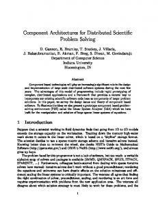
B. FORTIS 1.1 Results Some interesting results from comparing fabrication on a standard and a high resistivity epitaxial layer have already been found via the use of charge collection efficiency scans. A white light source was focused down to a 2µm x 2µm spot size and then horizontally scanned across the centre of the diodes of three adjacent pixels. The charge collection from the three pixels was then analysed by looking at the location of the spot and the resulting signal obtained out of each pixel in turn.
B. TPAC
Figure 6 shows the results from the standard resistivity epiTPAC (Tera-Pixel Active Calorimeter) is a MAPS sensor de- taxial layer. The geometric features of the pixels are immedisigned for a tera-pixel electromagnetic calorimeter at the Inter- ately clear; the peaks represent the positions of the diodes (i.e. national Linear Collider [3], [11]. The sensor contains ~28,000 where the spot was focused directly on the pixel of interest), 59
using 50kVp x-rays from an x-ray tube. In-between the irradiations, when not being tested, the chips were stored at −25 ◦ C. It was found that the noise significantly increased beyond 500kRad to a point where the signal-to-noise ratio decreased substantially and a MIP would not be reliably detectable, therefore the suggested radiation tolerance for FORTIS 1.0 is between 500kRad-1MRad. The noise distribution for 0kRad and 500kRad is given in Figure 8. A logarithmic increase with respect to irradiation level was found between 0-500kRad from 6-9e-rms, and the noise distribution clearly spreads out, suggesting that random telegraph signal noise and 1/f noise has increased, which are both associated with charge trapping in the source follower transistor gate oxide and the corresponding silicon-silicon dioxide interface [13].
and the dips mark where metal covers the pixel and light cannot get through. However, there are secondary peaks present within these scans, which represent the charge collected when the spot is focused on an adjacent pixel. These secondary peaks represent crosstalk.
Figure 6: FORTIS 1.1 Charge Collection Scan - Standard resistivity. The peaks and troughs represent the diode and metal within the pixel respectively, and the secondary peaks represent crosstalk
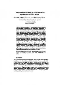
Figure 7 shows the results from the high resistivity epitaxial layer. The geometric features are again apparent, but the secondary peaks have significantly diminished. This shows that crosstalk has been reduced within the pixels, as the primary charge transport mechanism has changed. Charge diffusion within the epitaxial layer to neighbouring pixels is reduced. In- Figure 8: Radiation Hardness RMS Noise Results from FORTIS 1.0 stead, charge is attracted by the electric fields extending deeper from a 32 x 32 Pixel Region into the epitaxial layer as described in Section II. and is therefore more likely to be collected by the nearest pixel. This clearly shows the benefits of using a high resistivity epitaxial layer.
D. Beam Test Results As part of the SPiDeR collaboration, FORTIS 1.0 and FORTIS 1.1 have just returned from a beam test at CERN, where they were tested with 120GeV pions. Both standard and high resistivity epitaxial layer chips were taken, as well as chips with and without deep p-well. The results are currently being analysed, and the benefits of using a high resistivity epitaxial layer should be visible. Some provisional results are shown in Figure 9, which show the first detection of MIPs with a 4T pixel architecture. TPAC also went to the beam test at CERN as part of six sensors in a stack. In conjunction with the sensors, three scintillators and photomultiplier tubes (PMTs) were used; two in front and one at the rear of the stack, to be able to detect the particles Figure 7: FORTIS 1.1 Charge Collection Scan - High resistivity. The when they entered the stack for producing time tags to correlate secondary peaks as in Figure 6 have diminished significantly the hits seen by the sensor with the time at which the particles were detected and confirm that tracks were seen throughout the stack. The data from the beam test is currently being analysed, but early indications show that the time tags from the scintillaC. Radiation Hardness Results tors and PMTs show good correlation with the hits from the senThe best pixel (as shown in Figure 5) from five FORTIS sors. Events were seen in all six sensor layers, showing that the 1.0 sensors was irradiated up to 1MRad in steps of 10kRad, particles were tracked through the stack. Results were also seen 20kRad, 50kRad, 100kRad, 200kRad, 500kRad and 1MRad in the sensors fabricated on a high resistivity epitaxial layer. 60
R EFERENCES [1] R. Turchetta. CMOS Sensors for the Detection of Minimum Ionising Particles. In Proceedings of the 2001 IEEE Workshop on Charge-Coupled Devices and Image Sensors, Lake Tahoe, Nevada, USA, 7 - 9 June 2001, pages 7–9, 2001. [2] J.A. Ballin et al. Monolithic Active Pixel Sensors (MAPS) in a Quadruple Well Technology for Nearly 100% Fill Factor and Full CMOS Pixels. Sensors, 8(9):5336, 2008. [3] J.A. Ballin et al. A Monolithic Active Pixel Sensor for a “Tera-Pixel” ECAL at the ILC. In Proceedings of the 2008 Topical Workshop on Electronics for Particle Physics, Naxos, Greece, 15 - 19 September 2008, pages 63–69, 2008.
Figure 9: Beam Test Results from FORTIS Showing MIPs “Hits”
V. C ONCLUSIONS AND N EXT S TEPS
[4] The SPiDeR (Silicon Pixel Detector R&D) Collaboration. https://heplnm061.pp.rl.ac.uk/display/spider/.
FORTIS has proved to be a very promising sensor for applications where low noise and high sensitivity to small amounts of charge are paramount. The noise was measured at the output of the best pixel of FORTIS 1.0 to be 5.8e-rms, which is a key low noise result for particle physics applications. This pixel has also been shown to be tolerant to ionising radiation up to 500kRad.
[5] R.A.D. Turchetta et al. Accelerated Particle and High Energy Radiation Sensor, 7 May 2004. US Patent App. 10/556,028. [6] O.V. Kononchuk et al. High Resistivity Silicon Wafer with Thick Epitaxial Layer and Method of Producing Same, 6 December 2001. US Patent App. 10/008,440.
FORTIS 1.1 has yet to be fully characterised, and results from all pixels, including the geometric and processing variations, are expected within the next few months. FORTIS 1.1 will also undergo radiation hardness testing, which will be of interest for characterising the use of a high resistivity epitaxial layer, as it is expected that the sensors fabricated on such a layer will be more tolerant to radiation.
[7] W. Chen et al. Active Pixel Sensors on High-Resistivity Silicon and their Readout. IEEE Transactions on Nuclear Science, 49(3):1006–1011, 2002. [8] A.G. Holmes-Siedle and L. Adams. Handbook of Radiation Effects. Oxford University Press, USA, 2002.
The TPAC sensor preformed well in the recent CERN beam test. TPAC will be taken to DESY for a beam test in early 2010 to be tested with 1-6GeV electrons and with tungsten layers within the stack with the aim of detecting electromagnetic showers.
[9] R.M. Guidash et al. A 0.6µm CMOS Pinned Photodiode Color Imager Technology. In Technical Digest of the IEEE International Electron Devices Meeting, IEDM’97, Washington DC, USA, 7th - 10th December 1997, pages 927– 929, 1997.
Both of these sensors were fabricated with the INMAPS 0.18µm process, with and without deep p-well, and on both a standard and a high resistivity epitaxial layer, allowing us to [10] C. Leyris et al. Impact of Random Telegraph Signal in fully assess the benefits of the process. CMOS Image Sensors for Low-Light Levels. In ProceedThe results lead on to discussions under the SPiDeR collaboings of the 32nd European Solid-State Circuits Conferration as to whether to pursue a 4T style digital electromagnetic ence, Montreux, Switzerland, 18th - 22nd September 2006, calorimeter (DECAL) sensor, or to pursue a TPAC style one. pages 376–379, 2006. Alongside this, FORTIS is also being assessed for scaling up to a 5cm x 5cm active area. [11] M. Stanitzki et al. A Tera-Pixel Calorimeter for the ILC. In Conference Record of the IEEE Symposium on Nuclear Science, Honolulu, Hawaii, 27th October - 3rd November 2007, volume 1, pages 254–258, 2007.
VI. ACKNOWLEDGEMENTS
The author would like to thank the rest of the SPiDeR collaboration: B. Allbrooke, O. Miller, N.K. Watson, J.A. Wil- [12] J.R. Janesick. Photon Transfer: DN–)[lambda]. Society son D. Cussans, J. Goldstein, R. Head, S. Nash, J.J. Velthuis of Photo-Optical Instrumentation Engineers, USA, 2007. P.D. Dauncey, R. Gao, Y. Li, A. Nomerotski, J.P. Crooks, R. Turchetta, C.J.S. Damerell, M. Stanitzki, J. Strube, M. Tyndel, [13] X. Wang et al. Random Telegraph Signal in CMOS ImS.D. Worm, Z. Zhang. Thanks also to Carl Morris, Daniel Package Sensor Pixels. In Technical Digest of the IEEE Interham and Tim Pickering for their contributions to the testing of national Electron Devices Meeting, IEDM’06, San Franboth sensors. cisco, USA, 11th - 13th December 2007, pages 1–4, 2006.
61