Advanced Real-Time Traffic Monitoring System based on V2X Communications Raik Aissaoui∗ , Hamid Menouar∗ , Amine Dhraief§ , Fethi Filali∗ , Abdelfettah Belghith§ , Adnan Abu-Dayya∗ ∗ Qatar
Mobility Innovations Center, Doha, Qatar {raika, hamidm, filali and adnan}@qmic.com § HANA Research Group, University of Manouba, Tunisia
[email protected] [email protected] Abstract—The number of vehicles on roads keeps increasing continuously, making the management of traffic flow, especially in big cities more and more challenging. One of the key enablers for having smooth traffic flows and better mobility is to rely on real-time traffic monitoring systems. These systems allow road operators to implement intelligent traffic management strategies such as the dynamic adjustment of timing and phasing of traffic lights and the adaptive road congestion charging. Moreover, better informed travelers will plan smartly their journeys and hence potentially contribute in reducing traffic jams. Traditional real-time traffic monitoring usually get real-time data from GPSequipped fleets and fixed sensors installed in specific locations. In this paper, a new real-time traffic monitoring based on emerging vehicular communication systems is proposed. The system enables traffic monitoring with higher reliability, accuracy, and granularity. The cluster-based V2X traffic data collection mechanism is able to gather more than 99% of the available data and reduce the overhead to one quarter when compared to other approaches. Keywords—ITS, Vehicular Communication, Traffic Monitoring, Cluster-based Routing, GeoUnicast.
I.
I NTRODUCTION
To ensure a best management of roads and roads users, it is important to have an accurate and real-time view of the traffic status. Traffic Monitoring Systems (TMS) collect and distribute real-time information about the vehicles on monitored roads. Real-time traffic data is usually used to increase the traffic efficiency, for example by tuning the timing cycles of traffic lights in selected intersections, or by re-routing the traffic through less congested roads. Traffic data is also used to feed simulation tools used for traffic impact studies and urban planning. Current TMSs rely on specific sensors such as vehicles counters and cameras, installed at selected locations, or GPS sensors installed in some vehicles to get estimates of the traffic status by fusing data received from multiple sources. Other solutions relay on mobile networks data where a number of connected mobile phones can feed the TMS with real-time location data. Traditional traffic monitoring systems usually focus on major streets given that sensors deployment and maintenance is a bit expensive hence they are not capable of providing accurate road traffic monitoring in urban cities. New advanced real-time TMSs that can provide accurate and scalable traffic monitoring will be enabled with the emerging vehicle to vehicle and vehicle to infrastructure (V2X) communication systems.V2X technology will enable a large set of new safety and nonsafety applications and contribute in having next generation of
Intelligent Transport Systems (ITS) including TMSs. In order to fully take advantage from the emerging V2X applications, ITS requires novel communication technologies and protocols. The IEEE has recently developed the WAVE (Wireless Access in Vehicular Environment) standard, including the IEEE 1609 protocol family and the IEEE 802.11p.The WAVE standard is based on 802.11 architecture; however, it achieves higher data rates and has a wider communication range. The European Telecommunications Standards Institute (ETSI) ITS Technical Committee (TC) has proposed a protocol stack based on a variety of existing and new access technologies to enable ITS applications.Both ETSI and IEEE standards specify a beaconing message generally referred as Cooperative Awareness Message (CAM). Each vehicle periodically broadcast (e.g. every 1 second) a CAM to other vehicles and roadside units (RSUs) in its vicinity. When a CAM packet is received by a RSU, it is processed locally and may be stored for further use. In this work, we suggest to immediately forward the received CAM to the TMS. Note that a CAM does only contain the location and velocity data of the sender, but also other many other useful information related to the vehicles status (e.g. status of the exterior lights, occupancy). A basic solution to benefit from this technology and enable an accurate TMS, is to install a large number of RSUs along the roads to get a real-time snapshot of all vehicles driving on those monitored roads. No doubt that the cost of such a basic solution is too high, making its deployment unrealistic. To overcome this cost limitation, this paper presents an advanced solution where only one or a limited number of RSUs are needed to monitor whole roads of several kilometers. A cluster-based real-time traffic monitoring system is developed where roads are divided into clusters with predefined size. The dynamically selected cluster heads are responsible of feeding the road’s RSU with other vehicles’ information. This helps gathering a large amount of vehicles’ information with reasonable overhead. For example, the proposed solution is able to collect 99% of vehicles’ information in the road and hence reducing to one quarter the overhead when compared to a non-cluster based data collection approach. The rest of this paper is organized as follow. Section II reviews related works. Section III presents the proposed solution, and Section IV describes the simulation studies and discusses the obtained results. Finally, we conclude the work and highlight future works.
II.
R ELATED WORKS
In this section we first present the key motivations of deploying a TMS. Then we highlight the major constraints that should be satisfied by any TMS. Finally, we present an overview of already proposed TMS. A. Motivations Traffic monitoring systems play a significant role in an intelligent transport system (ITS) by providing the valuable information related to road traffic parameters. Such information not only benefits to traffic management, but also assists travelers to reach their destinations with the least time and energy consumption. These systems would be useful both in reducing the workload of human operators and in warning drivers of dangerous situations. In fact, such system automatically monitor the road and predict an imminent traffic jam or accidents and thus reduce the number of accidents. TMS integrates several advanced technologies to collect, transmit and process the traffic data. Newly-developed TMS relies on RFID, GPS and other sensors technologies to collect real-time traffic information. These sensors are usually interconnected through wireless sensors networks or cellular technologies to a Processing Center. The Processing Center receives the information and calculate traffic parameters such as vehicle quantity, vehicle speed, vehicle density and flow rates. Finally, it sends them back to the vehicles. B. Constraints Any TMS should satisfy a set of constraints. First of all TMSs should scale with the vehicle density and as a consequence with concurrent data transmission/channel access. TMS should also correctly handle emergency traffic flows. Accurate traffic data acquisition is essential for effective traffic monitoring. We use for example video camera to extract traffic parameter. If we do not care about light effect, data extracted could not be accurate. Another important issue to be considered is the reliability of information. Reliable traffic data are an important planning basis for assessing traffic situations and forecasting traffic. If the data are unreliable then the control decisions and the information given may be inappropriate. The primary security and privacy challenges that TMSs face are to ensure the integrity of data containing speed and position information and to maintain privacy for the drivers. C. Background statement In order to acquire the traffic parameters, one of the most used technology over the last fifty years were the inductive loops embedded in the roadways. Shin-Ting et al. [1] set round inductive loop sensors with square loops to analyze of the travel time and speed at both freeway corridor and individual freeway. Nonetheless, these sensors are limited to a certain road section and require putting up nodes at different points. Therefore, they require high installation and maintenance costs. Even worse, such procedures will cause roadway destruction and lane closure for several days. The traffic monitoring research field is experiencing a sustained growth. Several sensing technologies have been investigated during the last 15 years. Many technologies are in use today includes magnetic sensor, pressure tubes, radar guns and
microwave sensors. These solutions give accurate traffic data and are considered as robust TMS. However, their deployment needs and costs are usually higher. As the cost of cameras and processors continues to decrease, vision-based sensing is becoming an increasingly popular alternative to traditional sensors for collecting data traffic. Camera-based TMSs are flexible and cost effective technologies [2]. In fact, cameras can easily be installed without disrupting traffic operation. Furthermore, a small number of cameras can observe multiple roads, lanes or a square. Generally, a video camera-based traffic monitoring system [3] consists of two main processes, namely vehicle detection and traffic parameter extraction. The foreground moving objects, which tend to be vehicles, will be extracted in the former process. It will then be evaluated in the later process in order to calculate traffic parameters. The major drawback of vision based systems is the sensitivity to varying lighting condition and weather condition and the requirement of the separation of the interested image and other objects. However, V2X is an emerging technology that will be used to enable advanced traffic monitoring systemswhere each vehicle becomes an accurate sensor. As all vehicles are supposed to be equipped with wireless communication system. The penetration rate will be high enough to enable advanced traffic monitoring, not only with high accuracy data, but also with high resolution and granularity. A traffic information aggregation and propagation scheme was proposed in [4] by Soyoung et al. Selected vehicles are equipped to collect from surrounding vehicles and broadcast the traffic information to their vicinity. However, the scheme can only generate a realtime traffic information about the road (such as events like traffic hazards, accidents and jams). This limitation can be explained by the vehicle mobility and a vehicle cannot get the long-term traffic information of the road (the average speed, traffic flow and average density of vehicles on the road section). Furthermore, the range of transmission of the traffic information is uncertain because only vehicles are responsible for forwarding data and they are not allowed to retransmit in case of network disconnection . Besides, the strategy that traffic information is rebroadcast by every vehicle may flood the network. In [5], Zhang et al proposed a new Traffic information aggregation and propagation scheme. RSUs collect and analyze vehicles’ real-time travel information extracted from messages sent by each vehicle. The information reach the RSU through a multi-hop communication from the concerned vehicles to the RSU in GeoUnicast mode [6] (an information sent from one node to another node located in a given target location). After that, the RSUs generate traffic information, which contains the average speed of vehicles, vehicle density, and events like traffic jam. Finally, the RSUs broadcast generated traffic information to all vehicles in the surrounding. After receiving the traffic information, the vehicles analyze it, then update locally the traffic condition information. Such a solution is not well optimized, as the network flooding problem still exists as each vehicle periodically transmits its travel information to the RSU. For a better delivery ratio and to reduce broadcast storms, vehicles are organized on a set of clusters, in which one vehicle or more (Cluster Head) gathers data in his cluster and send them after to the next cluster. Cluster-based solutions provide less propagation delay and high delivery ratio with also bandwidth fairness [7]. In [8] clustering is based on
geographical data collection. The road is divided into segments and in each segment Cluster Head(CH) will be elected. In [9] authors proposed a clustering approach for traffic monitoring and routing the CH election is done based on distance and direction information. Vehicles are added into the cluster when they are below TH DISTANCE from CH (TH DISTANCE is a computed parameter to help in obtaining the optimal length of cluster). The cluster is formed based on the direction of vehicles which helps in forming a stable cluster. The main drawback in Cluster-based solution is the overhead created by cluster head election process. Packets (Query and Response) exchanged to elect CH create more overhead for V2V communication. III.
C LUSTER - BASED REAL - TIME TRAFFIC MONITORING
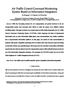
Fig. 1: Clustering architecture
SYSTEM
A. Location table data structure The ETSI TC ITS architecture assumes that each vehicle maintains a data structure holding information about the vehicle vicinity called the location table [6]. An entry in the location table is allocated to a vehicle’s neighbor and contains the following elements: (i) vehicle identification (ID), (ii) a timestamp of the geographical position, (iii) a position vector (Latitude, Longitude, Velocity, Heading (direction)). The location table is periodically updated based on the information contained in the received network beacons. An entry is considered fresh as long as a new message is received from the vehicle’s neighbor in the last N seconds. N is a lifetime timer related to each entry in the location table. When N expires, the entry is the location timer deleted. We assume that an RSU is placed at each crossroad (i.e. at the road section boundary). Furthermore, each vehicle retrieves its coordinates and speed using a satellite navigation system (such as the Global Positioning System (GPS)) 1 . A basic real-time traffic monitoring system can be illustrated as follows. The vehicle periodically sends its location information to the RSU of the road section on which it is located in GeoUnicast mode [5]. Such traffic monitoring system is not efficient as it is costly in term of overhead and can lead to a high collision rate. Therefore, we design an advanced mechanism to do this in a less costly way. We propose a new scheme to collect vehicles’ information where only selected vehicles on the road will be transmitting all data sufficient to build an accurate traffic condition information. To do so, we propose to use clusteringbased real-time traffic monitoring system, where each clusterhead vehicle transmits to the closest RSU the location and the velocity information of all vehicles located in its cluster.
beacon with a frequency 10 Hz (10 beacons every second) for one hop (only first neighbor). Each vehicle embed a location table where it saves all informations gathered from received beacons.
Fig. 2: Clustering protocol
B. The clustering algorithm In the following, we present our clustering algorithm to enable a lightweight real-time traffic monitoring system. We logically divide the road into fixed-sized cluster as shown in Fig. 1. The length of a cluster is predefined and the width is set to the width of the city road. We assume that each vehicle is equipped with a satellite navigation system (such as the Global Positioning System (GPS)) and a digital map augmented with the list of the city cluster centers. Both vehicle and RSUs use 802.11p communication technology [10]. Vehicles exchange 1 http://www.gps.gov/
In order to limit the overhead of our solution, the nearest vehicle to the cluster center is automatically selected as the cluster-head. It is therefore responsible of transmitting data to the RSU by means of GeoUnicast communication. as shown in Fig.2. (1) Every inter-update time (the delay between sending two consecutive information updates to RSU) each vehicle launches information update.(2) It checks if it is the nearest vehicle to the cluster center to which it belongs. It gets the nearest cluster center by calculating the Euclidean distance between its position and the position of all cluster center of the city saved in the digital map.(3) Then, it calculates Euclidean
Map dimension Road width Speed Vehicle inter-space Vehicle radio range Propagation Loss model
simulation duration Confidence Interval Beacon frequency Market penetration rate
3x3 km 4m each lane randomly between 10 and 20 m/s randomly between 50s and 125m 300m LogDistancePropagationLossModel ReferenceLoss: 46.8588 Exponent: 3 120s 95% 10 Hz 100%
TABLE I: Simulation parameters Fig. 3: Map distance between each vehicle in its location table (including itself) and this nearest cluster center. (4) If and only if it is the nearest vehicle, (5) it sends to the next RSU an updating packet which contains its own location information as well as all its neighbors’ location information. The updating packet is sent using GeoUnicast routing protocol. We design this clustering strategy in order to reduce the location update overhead. In addition, our clustering strategy does not introduce any additional control message to elect the cluster head. C. Disconnected networks Some cluster might be empty of vehicles. Therefore, the transporter, a vehicle which has a packet to forward, stores the packet and carries it until it crosses another forwarder or the destination RSU itself. All vehicles are equipped with wireless system 802.11p. But to be more realistic, we can consider what we called the market penetration rate of the wireless communication devices, only a percentage of vehicles is equipped with wireless system. Hence, disconnected networks can happen even in croweded roads. IV.
P ERFORMANCE EVALUATION
In order to evaluate the performance of our solution, we use the NS3 version 2 of the simulation platform developed by the European research project iTETRIS [11]. A. Simulation scenario The region is 3 Km x 3 km, with a total of 12 Km (1 lane each direction). The sub-segment size is 1 Km, resulting in a total of 12 sub-segments. There are a total of 4 intersections (Fig. 3). We set vehicle’s speed randomly between 10 and 20 m/s. We choose the vehicle inter-space randomly between 50m and 125m. We set the vehicle radio range to 300 m. The propagation Loss model is ”LogDistancePropagationLossModel”. We set the beacon frequency at 10 Hz. We use 1 RSU at each intersection. The simulation duration is 120 seconds. In each scenario, we run as many trials as needed to reach a 95% confidence interval at ε = 1% of the average value. In our simulation, the update starts from the 5th seconds. Tab. I summarizes the different simulation parameters. 2 http://www.nsnam.org/
B. Metrics In our simulations, we consider the following metrics: •
The fraction of vehicles saved in the RSUs: It is the average of number of vehicles saved in the location tables of all RSUs divided by the real number of vehicles in the map.
•
The overhead: The average size of updating packets generated by both clustering updating and individual updating.
•
The success rate: The average number of packets that have been successfully received at RSU over the number of packets that have been initially triggered from the source.
•
Vehicles positions’ error: The difference between the vehicle position saved in RSU and its real position at an instant t in meter.
C. Results We perform several simulations by varying the cluster dimension from 200m to 800m and inter-update time from 1s to 6s. We target to get the best overview (the highest fraction possible i.e all node in the road are seen by the RSU) with the lowest overhead possible. We have to find two optimal parameters (cluster-size and inter-update time) to fulfill our objective. We compare our contribution with a regular TMS [5] where all vehicles update individually to the next RSU. We plot the inter-update time vs. the fraction of the vehicles saved in RSU (percentage) for different cluster size in Fig. 4 (cluster size equal to zero refers to the regular TMS i.e without clustering). We observe that the fraction decreases whenever we increase the inter-update time and the cluster size. We notice that for the inter-update time starting from 1s to 3s the fraction is almost 100% for cluster size from 200m to 500 m (detailed in Tab. II). We plot the induced overhead for different inter-update times and cluster sizes in Fig. 5 (cluster size equal to zero refers to the mechanism without clustering). We remark that the overhead decreases whenever we increase the inter-update time and the cluster size. For inter-update time equal to 1s and 2s, we observe a signaling storm (about 9200 KB for Inter-update equal to 1s
1
2
3
4
5
Inter-update time (sec)
12000 10000
12000
8000
10000 8000
6000
6000
4000
4000
2000
2000
0
Overhead (KB)
Fraction (%)
100 90 80 70 60 50 40 30
100 90 80 70 60 50 40 30
0
0 100 200 300 400 500 Cluster size (m) 600 700 6 800
1
2
3
4
5
Inter-update time (sec)
Fig. 4: Fraction of vehicles information’s saved in the RSU (%)
0 100 200 300 400 500 Cluster size (m) 600 700 6 800
Fig. 5: Overhead
100
1
3
6
98.9078 98.4847 98.5066 72.084
93.7049 95.9146 95.8128 66.4478
66.5243 55.2631 55.1184 37.6608
TABLE II: Fraction (%)
80
Success rate (%)
Inter update time(s) Cluster size(m) 0 200 400 800
60
40
20
and cluster size equal to 200 m). For an inter-update time equal to 3s, the overall overhead experiences a significant decrease (overhead is about 1500 KB for cluster size equal to 400 m). In Fig. 4, we see that the best fraction is given by an interupdate time equal to 1s. For 3s, the fraction is still near 100% (about 96%). The overhead (Fig.5) gives the advantage to an inter-update time equal to 3s as we get less packet exchange and we still have a high fraction. Starting from inter-update time equal to 4s, we observe a drop in the surface in Fig. 4 (83% less than 90%). We conclude that for such environment, an inter-update time equal to 3 sec is a good trade-off between the saved fraction and the overhead. For inter-update time equal to 3s (see Fig. 4 and Tab. II), we observe that a cluster of 400m gives us a good overview of the current traffic (95.81%). In Fig. 4 for the same interupdate time equal 3s, the fraction of cluster size equal to 400m (95.81%) is better than the fraction of the regular TMS (93.70%). Even it looks similar to the solution regular TMS for inter-update time equal 2s (95.9%). Both strategies give a whole overview of road. However, we notice that we reduce the overhead more than 4 times which is an important improvement. Fig. 6 plots inter-update time vs. Success rate for every cluster size and the regular TMS. The success rate in Fig. 6 shows that using our solution it can reach about 99% and it is always better than regular TMS (79% for inter-update time equal to 1s). To assert our proposal and show its efficiency, we plot vehicles positions’ error (Fig.7) with previous simulation parameters (see Tab. I) and we vary vehicles density. We compare
0 1
2
3
4
5
6
Inter update time (s) Regular TMS cluster size=200 m cluster size=300 m cluster size=400 m
cluster size=500 m cluster size=600 m cluster size=700 m cluster size=800 m
Fig. 6: Comparison of Success rate
between our proposal (clustering TMS with cluster size equal to 400m) and the regular TMS for the optimal inter-update time (3s). We notice that our proposal minimize position’s error. It is less than 8m comparing the other solution that reaches 16m of error. Besides, the gradient of our proposal’s curve is small which indicates that our proposal is scalable for high density. The Fig. 8 is a snapshot taken from one of simulations randomly to present different vehicles positions. As shown, we notice that when using clustering TMS, we get more accurate vehicles’ position comparing to the regular TMS. Besides, for some vehicles even their positions are not given for the regular TMS. These difference of availability and accuracy is due to the bottleneck results from the non-clustering way: some nodes (vehicles) play the role of forwarder. These nodes undergo a huge amount of data to be forwarded. In fact, it will result some delay in queue and loss which will have a repercussion on the precision of vehicles’ position in the RSU. Even for RSUs, in our proposal the clustering TMS, RSUs will receive less packets because only cluster heads generate packets. Hence, we minimize packet loss.
possible. We proposed a clustering based updating where only cluster head updates TMS with all vehicles informations saved in its cluster. An experimental study permitted to evaluate its performance on NS3. With the proposed vehicle’s parameters, an inter-update time equal to 3 sec and a cluster size equal to 400 m is an optimal solution to get a clear overview of the road. We reduce the overhead more than 4 times which is an important improvement.
20 18 16 14
Error (m)
12 10 8 6 4 2 0 100
150
200 250 300 Number of vehicles per km (vehs/km) Regular TMS
350
400
Clustering TMS
Fig. 7: Vehicles positions’ error for inter-update time equal to 3s
ACKNOWLEDGMENTS
7
This work was made possible by NPRP grant # 09-8112-308 from the Qatar National Research Fund (a member of The Qatar Foundation). The statements made herein are solely the responsibility of the authors.
6 5
Longitude (m)
In Future work we intend to reduce the number of submitted node (so the overhead) by adding vehicles Information to the forwarded packet as well as the size does not reach the Maximum size instead of generated a new packet for every cluster head. Also this work is a part of a location service proposal in city environment. Where clustering mechanism will update servers with latest vehicles informations and give the best overview of all vehicles in the city with the lowest overhead possible.
4 3
R EFERENCES
2 1 0 −1 200
400
600
800
1000
Latitude (m) RSU Reality
Regular TMS Clustering TMS
Fig. 8: A snapshot of vehicles positions
D. Discussions As it is mention above RSU cleans its location table every 5s (entries which are older than 5s are deleted). We demonstrated in the previous section that the inter-update time equal to 3s is a good parameter to get the best overview of road. Our solution (i.e., the clustering TMS where only cluster heads transmit the update packet) reduces the total overhead. In fact, the gain is in the packet header because vehicles information will be sent anyway but reducing the sender will subtract the size of useless packet header from the total overhead. Thus, we reduce the overhead to one quarter. Also our solution leads to better success rate because only few vehicles (cluster heads) sent packet knowing that the packet is forwarded by other vehicles in greedy way. So, it will be less packet loss due to contention. Finally, our proposal improves vehicles positions’ error. Because, even for high density, only cluster headers send the packet to update the RSU with other vehicles positions. So it depends always from the cluster size. V.
C ONCLUSION
In this paper, we are interested to get a better solution to update TMS with vehicles information with lowest overhead
[1] S.-T. Jeng, Y. Tok, and S. Ritchie, “Freeway corridor performance measurement based on vehicle reidentification,” Intelligent Transportation Systems, IEEE Transactions on, vol. 11, no. 3, pp. 639 –646, sept. 2010. [2] H.-Y. Cheng and S.-H. Hsu, “Intelligent highway traffic surveillance with self-diagnosis abilities,” Intelligent Transportation Systems, IEEE Transactions on, vol. 12, no. 4, pp. 1462 –1472, dec. 2011. [3] P. Laparmonpinyo and O. Chitsobhuk, “A video-based traffic monitoring system based on the novel gradient-edge and detectionwindow techniques,” in Computer and Automation Engineering (ICCAE), 2010 The 2nd International Conference on, vol. 3, 2010, pp. 30–34. [4] S. Park and C. Zou, “Reliable traffic information propagation in vehicular ad-hoc networks,” in Sarnoff Symposium, 2008 IEEE, april 2008, pp. 1 –6. [5] F. Zhang, J. Hao, and S. Li, “Traffic information aggregation and propagation scheme for vanet in city environment,” in Broadband Network and Multimedia Technology (IC-BNMT), 2010 3rd IEEE International Conference on, oct. 2010, pp. 619 –623. [6] “Etsi ts 102 636-4-1 v1.1.1 (2011-06), intelligent transport systems (its); vehicular communications; geonetworking; part 4: Geographical addressing and forwarding for point-to-point and point-to-multipoint communications; sub-part 1: Media-independent functionality,” Tech. Rep. [7] L. Bononi and M. Di Felice, “A cross layered mac and clustering scheme for efficient broadcast in vanets,” in Mobile Adhoc and Sensor Systems, 2007. MASS 2007. IEEE Internatonal Conference on, 2007, pp. 1–8. [8] S. S. I. Salhi and M.Cherif, “A new framework for data collection in vehicular networks,” in IEEE ICC2009 Dresden, June 14-18, 2009. [9] M. Venkata, M. Pai, R. Pai, and J. Mouzna, “Traffic monitoring and routing in vanets - a cluster based approach,” in ITS Telecommunications (ITST), 2011 11th International Conference on, 2011, pp. 27–32. [10] A. Ibanez, C. Flores, P. Reyes, A. Barba, and A. Reyes, “A performance study of the 802.11p standard for vehicular applications,” in Intelligent Environments (IE), 2011 7th International Conference on, 2011, pp. 165–170. [11] V. Kumar, L. Lin, D. Krajzewicz, F. Hrizi, O. Martinez, J. Gozalvez, and R. Bauza, “itetris: Adaptation of its technologies for large scale integrated simulation,” in Vehicular Technology Conference (VTC 2010Spring), 2010 IEEE 71st, may 2010, pp. 1 –5.