2016 International Conference on Computation of Power, Energy Information and Communication (ICCPEIC)
Advanced Traffic Light Control System Using Barrier Gate andGSM M. Ashwin Kumaar, G. Akshay Kumar
S.M. Shyni
Department of Electrical and Electronics Engineering,
Department of Electrical and Electronics Engineering,
Sathyabama University, Chennai
Sathyabama University, Chennai
[email protected]
[email protected]
Abstract- The aim of the project is to design a density based
captured in the signal is processed and converted into gray
traffic light control system interfaced with a barrier gate and a
scale image then its threshold is calculated in order to
GSM technology. The signal timing changes automatically with
determine the number of vehicles present in the image. After
the density of the traffic and delay is provided with the help of
calculating
microcontroller. When the signal is red the interfaced barrier
direction is known, based on which signal will be allotted for
gate closes and a buzzer notifies the closing of gate, thereby blocking the traffic but when the signal is green the same barrier opens and allows a proper flow of vehicles to avoid traffic jam. The density of traffic is detected using IR sensor and the output is given to the microcontroller for timing change of the signal, and buzzer action. In front of the barrier gate a stop line is drawn and with the help of another IR sensor, the vehicle is tracked whenever it crosses the stop line. If the vehicle crosses the stop line, the intimation is given to the nearby control room, carried out by GSM technology. PIC microcontroller is used for signal timing change based on density of traffic.
Keywords- PIC
microcontroller,
IR
the
count
of
vehicle,
particular side. By referring
[5],
the
maximwn
density
the author proposed a
dynamic time based coordination schemes where the green signal time of the traffic light is assigned based on the present condition of the traffic. Certain approaches has been done to collect data from vehicles and the input is processed using computer and microcontroller and finally display on the traffic system. [6] is concerned with an overview on FPGA design implementation of advanced traffic light controller system that as a VLSI design using VHDL and also its comparisons with traffic light controller using IR sensor and microcontroller. FPGA design based on dual traffic light system has a simple
sensor,
DC
Motor,
circuit with high computing speed. [7] shows density of traffic using IR sensor and OCR. When the density of the vehicle is
ARM-7 Microcontroller, GSM module, Buzzer
low, it is analyzed by using IR sensor, according to which I.
timing is changed. OCR is used to identify the vehicle which
INTRODUCTION
In the present day to day life vehicular traffic is increasing all over the world, especially in urban areas. Hence traffic control
should
be
modified
to
better,
considering
the
increasing demand arises. The system [1] consist of a traffic light controller and simulator that allows to study different situations of traffic
in city and overviewing the traffic of
entire city by visual monitoring using CCTV. Using wireless sensor, it sense the density of traffic. In [2], the system consist of IR transmitter and IR receiver. Microcontroller controls the IR system and counts the number of vehicles passing through the road. Microcontroller also store vehicle count in its memory. Based on different vehicle count, the microcontroller takes decision and updates the traffic light delay as a result. The traffic light is located at a distance from the IR system. Thus
based
on
the
vehicle
count
microcontroller
states
different ranges for traffic light delays and control them accordingly. But comparing with [3], it involves the use of
breaks the traffic rules during stop signal. Warning is given to individual person through message alert if they violate the rules for the first time. If the same vehicle is captured and analyzed for the second time then it is taken as a complaint and is forwarded to nearby control room. In [8], the author proposed a scheme in which the time period of green light and red light is assigned according to the density of the traffic present at that time by using IR sensor. Based on this density, the glowing time of green light is assigned by the help of microcontroller. With reference to [9], the paper attempts to address the problem of traffic congestion caused at traffic signal. The traffic light duration in the conventional method have been constant which turns out to be a big drawback. This has been done using image processing. The traffic control is analyzed
through
the
data
collected
from
camera
and
depending upon the volume of traffic, traffic light duration are set.
wireless sensor technology to sense traffic near circle or
II. MOTIVAnON
junction and then able to route the traffic based on availability. The system does not require any external device in vehicles,
In our day to day life, all faces a simple problem in road
so can be implemented in any traffic system quite easily. The
i.e. traffic jam. This traffic problem occurs due to increase in
system uses wireless sensor network technology to sense
vehicle density. Because of these many criminal activities
vehicle and a microcontroller based routing algorithm for excellent traffic management. In [4], the system consist of an image processing technique where it captures the image of traffic density with respect to nwnber of vehicle. The image
occur like violation of the traffic rules, causing trouble to people crossing the road etc. Due to massive growth in urbanization and traffic violation, automatic based traffic light system is developed. But at times, existing system gets failed
978-1-5090-0901-5/16/$31.00 ©2016 IEEE
291
M. Ashwin Kumaar et at: Advanced Traffic Light Control System Using Barrier Gate and GSM
creating problem to existing traffic control system. Examining
to improve the traffic violation and promotes a better way of
these current situation, a system is designed which reduce the
following
violation of traffic rules by implementing new ideas to the
development of GSM module it is now easy to transmit and
existing one.
receive information which makes it a better option to use in
the
traffic
rules
and
regulation.
With
the
this system.
III. PROBLEM DEFINITION The most common drawback with all the proposed system is that making vehicle to stand in a proper line due to which many of the traffic jam occurs today. Also affects the people crossing the road especially the two wheelers who are in hurry cross the stop line, violates the rules and become a barrier for big vehicles coming from other direction thereby causing delay in traffic signal. To overcome this problem a barrier gate and buzzer is implemented thereby making it a voluntary for the vehicle to stop before stop line by closing the barrier gate, when the signal is red. A buzzer intimates the vehicle that the gate is going to get closed. When the signal is green, gate will be open so as to achieve a proper flow of the traffic. Even though barrier is provided some vehicles may be standing close to the barrier and some may even try to pass underneath the barrier to move quickly. In order to overcome this, a GSM module is used to detect the vehicle crossing stop line and maintains a proper traffic flow. IV. PROPOSED METHODOLOGY
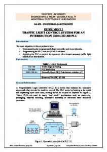
Fig. 1.
The proposed system consists of a PIC microcontroller which does all the function according to program interfaced. Power supply is given to the microcontroller and the IR sensor on both the side of the road sense the density of traffic and
Proposed system block diagram
A. PIC Microcontroller
PIC16F877A microcontroller is an 8-bit microcontroller
gives the information to PIC microcontroller. The controller
which
provides output signal to traffic light, barrier gate and buzzer
Operating speed: 20 MHz clock input 200 ns instruction cycle
which act accordingly. If the density is more, then red signal is produced and the motor activates the barrier to close and when green signal is given the barrier is made to open so as to allow traffic to flow. Buzzer is provided to alert the people regarding
is
a
RISC
Architecture.
It
has
35-Instructions,
and can run up to 8K x 14 words of Flash Program Memory of EEPROM Data Memory
B. IR Sensor
the signal and the closing of barrier gate. Additionally an IR
The IR Sensor is a proximity sensor. It is used for collision
and GSM are provided to prevent people to cross stop line. If
detection. The module consist of an IR emitter and IR receiver
they cross the stop line, IR detects the vehicle and gives the
pair. The IR receiver always detects an IR signal. The output
warning to the driver. Also information will be sending to
of sensor is high whenever the IR frequency is low. The LED
nearby control room. First the power supply is given to the microcontroller which activates the IR sensor. With the help of IR sensor, the vehicle crosses and stand in the lane so when density is high
indicator helps user to check the status of the sensor without using any additional hardware. It gives a digital output. C. Stepper Motor
the vehicle will block the IR transmitter and IR receiver, the
A step motor is an electromagnetic rotor that mechanically
corresponding cut off signal is given to the microcontroller,
converts digital pulse inputs to incremental shaft rotation. The
which allots the signal to the particular lane and it activates the
rotation is not related to the number of input pulses, but its
barrier gate and buzzer to the allotted lane. After the barrier is closed, an IR will sense the vehicle which crosses the stop line and through GSM technology, the message is sent to nearby police control room. The proposed system, fig.l.consists of a PIC microcontroller which does all the function according to program interfaced. IR and GSM are connected to ARM-7 microcontroller which analyses the number plate with the help
speed is related to the frequency of the pulses. In each steps, the motor holds its' position (and its' load) without the aid of clutches or brakes. Thus a step motor can be controlled so that it rotates a certain number of steps, producing mechanical motion and then holds its load when it stops. D. Buzzer
of camera .The image captured in the traffic is processed and
The buzzer circuit consist of a relay in series with a small
converted into grey scale image then its threshold is calculated
audio speaker. When the switch is pressed, the relay will
based on which the contour has been drawn in order to find the number plate of the vehicle. This type of system will help
operate by the transformer primary and close the relay contact. The relay operates and normally the closed contact will open, removing power from the relay and the sequence repeats
978-1-5090-0901-5/16/$31.00 ©2016 IEEE
292
2016 International Conference on Computation of Power, Energy Information and Communication (ICCPEIC) E. ARM-7 Microcontroller
ARM-7 microcontroller board based on a l6-bitl32-bit CPU with real-time emulation and embedded trace support, that relates microcontrollers with high-speed flash memory ranging from 32 kB to 512 kB. A l28-bit wide memory interface and unique accelerator enable 32-bit code execution at the maximum clock rate.
F.
GSM module GSM (Global System for Mobile) is SIM900 Quad-band
GSM / GPRS device, works on frequencies 850 MHZ, 900 MHZ. It is very compact and easy to use as plug in GSM Modem. The Modem is designed with 3V and 5V interfacing circuitry,
which
allows
User
to
directly
interface
with
Microcontrollers (PIC, AVR Arduino, 8051, etc.) as well as Fig. 3.
3V Microcontrollers.
Traffic light result
VI. HARDWARE IMPLEMENTAT10N
V. SIMULATION ANALYSIS The PIC microcontroller is compiled by using the C compiler. IR sensors have been replaced by switches, also it is impossible to interface sensor in a simulation circuit. LED lights have been interfaced across each road to represent the signal system. The Switch is closed to represent the density of the traffic system. When the switch is closed it indicates that the traffic is high and gives preference to that particular side. Likewise all the other side's functions based on the position of switch. In a normal condition the traffic light works in a loop. The coding will be running the loop of each LED. when switch is closed, some interrupt is given to the microcontroller which takes that as the input and changes the regular action and the particular LED will glow green. And after a fixed time the loop continues back to the normal traffic light system.
Fig. 4. Hardware Setup
The hardware consist of a PIC microcontroller through which all the IR sensor are connected internally. PIC consists of a voltage regulator, bridge rectifier, transformer which converts l2v dc supply to 5v supply suitable for PIC. When the IR sensor is blocked the input signal is given to PIC and red led glows on
particular lane. After that the barrier
connected with a stepper motor activates with a buzzer sound.
VII. CONCLUSION The above proposed system for advanced traffic light control system using barrier gate and GSM is advantageous to many existing system in this heavy population of vehicle. The barrier gate system making it easy to implement in the intersection having heavy density of vehicle. GSM helps in maintaining the rules and regulation thereby helping police to take over a proper control over the road. It is also cost inexpensive and does not require any external device in the Fig. 2.
Traffic light result
vehicle making it more practical than the existing system with great result. Also the use of IR sensor helps in calculating the
978-1-5090-0901-5/16/$31.00 ©2016 IEEE
293
M. Ashwin Kumaar et at: Advanced Traffic Light Control System Using Barrier Gate and GSM
density of traffic and many more sensors can be used based on the requirements and the feasibility of the location. REFERENCES [I]
[2]
[3]
[4]
[5]
[6]
[7]
[8]
[9]
Pramod Sharma and Akanksha Mishra, "Density Based Intelligent Traffic Control System Using IR Sensor", International Journal Of Scientific Research, Volume 4, May 2015 Issue no. 5, pp. 3-4. Amrita Rai and Govind Singh Patel," Multiple Traffic control Using Wireless Sensor And Density Measuring Camera", Sensor and Transducer Journal, Volume 94, July 2008,lssue no. 7, pp. 126-132. Monika. G and Kalpana. N, "An Intelligent Automatic Traffic Light Control Using Embedded System", International Journal Of Innovative Research In Science, Engineering And Technology, Volume 4, April 2015, Issue no. 4, pp. 19-27. Nilay Mokashi, "Intelligent Traffic Signal Control Using Image Processing", International Journal Of Advance Research In Computer Science And Management Studies, Volume 3, October 2015, Issue no. 10, pp. 137-143. Padmini G. Kaushik and Vishal D. Dahake, "Design Of Intelligent Traffic Light Controller", International Journal Of Engineering In Science And Management, Volume 5 ,January 2015, Issue no. I, pp. 120-129. Promila Sinhmar, " Intelligent Traffic Light And Density Control Using IR Sensor And Microcontroller", International Journal Of Advanced Technology and Engineering Research, Volume 2,March 2012, Issue no. 2, pp. 30-35. Rashid Hussian and Sandhya Sharma, "Automated Intelligent Traffic Control Using IR Sensor", International Journal Of Software Computing And Engineering, Volume 3, July 2013, Issue no. 3, pp. 7881. Tina R. and Sharmila Sujatha G, "Density Based Traffic signal System", International Journal And Magazine Of engineering Technology Management And Research, Volume 2, September 2015, Issue no. 9, pp. 149-151. Vidhya K and Bazila banu A , " Density Based Traffic Signal System", International Journal Of Innovative Research In Science Engineering And Technology, Volume 3, March 2014, Issue no. 3, pp. 2218-2223
978-1-5090-0901-5/16/$31.00 ©2016 IEEE
294