University of Hawaii. Hugh J. Watson. University of Georgia. CAIS SENIOR EDITORS ... Ruth Guthrie. California State Univ. Alan Hevner. Univ. of South Florida.
Mennecke, B.E., and M.D. Crossland (1996) "Geographic Information Systems: Applications and. Research Opportunities for .... Edward A. Stohr. Editor-at-Large.
Dec 5, 2017 - Wiley: Testing Object-Oriented Software - David C. Kung, Pei Hsia, Jerry Gao ... Object-oriented programming increases software reusability, extensibility, ... Beginning Object · Oriented Programming · with C# by Jack Purdum.
Advances in Data Analysis. Theory and Applications to Reliability and Inference, Data Mining,. Bioinformatics, Lifetime Data and Neural Networks. C.H. Skiadas.
mining. In functional data analysis , as functional random variable can ... In section 2 we define the concept of distribution of functions and recall the notion of ...
Ong Chee Tiong. Index. 119. Paper width: 433.62pt. Paper height: ... Johor Bahru, Johor, Malaysia. Normah Maan. Department of Mathematical. Sciences ...
to model and forecast the demand for tourism in ... different econometric methods used to forecast tourism ... Tourism demand can be measured using tourist.
Oct 18, 2016 - HFC245fa, High. Temp-High Press 32 (2000) 441e447. [85] X. Dong, M. Gong, J. Liu, J. Wu, Experimental measurement of vapor pressures.
The concept of enhanced heat transfer and flow mixing using swirling jets ... among these are the degree of swirl (based on the swirl number, S) and the spatial.
tics of Mount Ida, the mapping (based on .... chaeological data of the western cemetery, ..... Green, S. W., Zubrow, E. B. W. (Eds.)., Interpreting Space: GIS and ...
Despite substantial progress in the US âwar on cancerâ declared in 1971, ... Representing the central process of cancer biology: Somatic cellular evolution.
(Frank and Nowak 2004; Crespi and Summers 2005; Pepper, Findlay et al. 2009; Greaves and. Maley 2012 ... 2009; Navin, Kendall et al. 2011; Shah, Roth et al.
temperature of humidifier. During the fuel cell operation, the humid gases are introduced to the fuel cell and they diffused to the MEA through the gas diffusion ...
practical errors for most traditional radiation engineering problems [Modest .... photons, generated by a 100 fs mode-locked laser, that were scattered out of a pin ...
University of Malaga, Spain, e-mail: [email protected]. taken place in ..... abcde. d q d q. 1 1 2 2. Five- phase IM. PMDC ia to id. Resolver. DC-bus. Two-level.
The use of ultrafast laser technology has become widespread in recent years for many emerging applications ...... of the ASME Early Career Tech. Conf., New ...
4502 Rachael Manor Drive ... Often the overall failure repair process in real ... random process, and considers how one can choose optimal repair policies that .... The organization of the conference was made possible by the hard work of a.
Mar 15, 2012 - Aquifer test. Well hydraulic. Analytical model. Numerical model. a b s t r a c t. Well hydraulics is a discipline to understand the process of flow to ...
Document Image Degradation Modeling (DIDM) has a long history and has been recognized since the beginning of DIAR [4,5]. The main objective of DIDM is to ...
Early work in business decision modeling spanned a broad spectrum of disciplines, ... in business computing was the development of spreadsheet software. ... in manufacturing settings for scheduling, inventory management, location, and ...
the reject water, or brine, and precipitation occurs. This type of fouling occurs only in high pressure membranes, nanofiltration (NF), and RO. Low pressure ...
Journal of Advances in Modeling Earth Systems. Supporting Information for. Explicitly Accounting for the Role of Remote Oceans in Regional Climate Modeling ...
May 8, 2012 - Zhaohui Lin 1,*, Jason K. Levy 2, Hang Lei 3 and Michelle L. Bell 4. 1 ..... Pope, C.A., III; Dockery, D.W. Health effects of fine particulate air ...
e erf k y dy γ Ï. â. -. â. = â. â. â â. â«. 1. 2. 2 D. D t γ Ï. = â. â +. â. 1. 2. D .... Macrelli,G. SGT100&ESG2016; Sheffield UK:2016. Dugnani,R. J.Non-Cryst.Sol. 471 (2017) ...
Ramez El-Masri Ramez and Gio Wiederhold: âData Model Integration Using the Struc- ..... Mike P. Papazoglou, Stefano Spaccapietra, Zahir Tari. Tilburg ...
Advances in Object-Oriented Data Modeling
Cooperative Information Systems Michael Papazoglou, Joachim W. Schmidt, and John Mylopoulos, editors Advances in Object-Oriented Data Modeling, Michael P. Papazoglou, Stefano Spaccapietra, and Zahir Tari, editors, 2000
edited by Michael P. Papazoglou Stefano Spaccapietra Zahir Tari
Advances in Object-Oriented Data Modeling
The MIT Press Cambridge, Massachusetts London, England
Preface: The Blossoming of Object-Oriented Data Modeling 1
Advances in Object-Oriented Data Modeling
xv
1
Moira Norrie
I
Behavioral Modeling 2
19 A Behaviorally Driven Approach to Object-Oriented Analysis and Design with Object-Oriented Data Modeling 21 Lois M. L. Delcambre and Earl F. Ecklund
3
Objects and Events as Modeling Drivers
41
M. Teisseire, P. Poncelet, and R. Cicchetti 4
On the Design of Behavior Consistent Specializations of Object Life Cycles in OBD and UML 65 Michael Schrefl and Markus Stumptner
II
Transformation and Reverse Engineering 5
105
Mapping an Extended Entity-Relationship into a Schema of Complex Objects 107 Rokia Missaoui, Robert Godin, and Jean-Marc Gagnon
6
Leveraging Relational Data Assets
131
M. P. Papazoglou and W. J. van den Heuevel
vi
III
Contents
Temporal and Dynamic Modeling 7
161
Temporally Enhanced Database Design
163
Christian S. Jensen and Richard T. Snodgrass 8
Modeling Object Dynamics
195
M. P. Papazoglou and B. J. Kr¨amer
IV
Modeling Interoperable Objects 9
219
Database Integration: The Key to Data Interoperability
221
Christine Parent and Stefano Spaccapietra 10
Identifying Objects by Declarative Queries
255
M. Gogolla
V
Modeling Object Collaborations 11
279
Conceptual Modeling of Workflows
281
Fabio Casati, Stefano Ceri, Barbara Pernici, and Giuseppe Pozzi 12
Coordinated Collaboration of Objects
307
G. Engels, Luuk Groenewegen, and Gerti Kappel
VI
Beyond Modeling 13
333 An Active, Object-Oriented, Model-Equivalent Programming Language 335 Stephen W. Liddle, David W. Embley, and Scott N. Woodfield
Index
363
Series Foreword
The traditional view of information systems as tailor-made, cost-intensive database applications is changing rapidly. The change is fueled partly by a maturing software industry, which is making greater use of off-the-shelf generic components and standard software solutions, and partly by the onslaught of the information revolution. In turn, this change has resulted in a new set of demands for information services that are homogeneous in their presentation and interaction patterns, open in their software architecture, and global in their scope. The demands have come mostly from application domains such as e-commerce and banking, manufacturing (including the software industry itself), training, education, and environmental management, to mention just a few. Future information systems will have to support smooth interaction with a large variety of independent multi-vendor data sources and legacy applications, running on heterogeneous platforms and distributed information networks. Metadata will play a crucial role in describing the contents of such data sources and in facilitating their integration. As well, a greater variety of community-oriented interaction patterns will have to be supported by next-generation information systems. Such interactions may involve navigation, querying and retrieval, and will have to be combined with personalized notification, annotation, and profiling mechanisms. Such interactions will also have to be intelligently interfaced with application software, and will need to be dynamically integrated into customized and highly connected cooperative environments. Morever, the massive investments in information resources, by governments and businesses alike, calls for specific measures that ensure security, privacy and accuracy of their contents. All these are challenges for the next generation of information systems. We call such systems Cooperative Information Systems, and they are the focus of this series. In layman terms, cooperative information systems are servicing a diverse mix of demands characterized by content—community—commerce. These demands are originating in current trends for off-the-shelf software solutions, such as enterprise resource planning and e-commerce systems.
viii
Series Foreword
A major challenge in building cooperative information systems is to develop technologies that permit continuous enhancement and evolution of current massive investments in information resources and systems. Such technologies must offer an appropriate infrastructure that supports not only development, but also evolution of software. Early research results on cooperative information systems are becoming the core technology for community-oriented information portals or gateways. An information gateway provides a “one-stop-shopping” place for a wide range of information resources and services, thereby creating a loyal user community. The research advances that will lead to cooperative information system will not come from any single research area within the field of Information Technology. Database and knowledge-based systems, distributed systems, groupware, and graphical user interfaces have all matured as technologies. While further enhancements for individual technologies are desirable, the greatest leverage for technological advancement is expected to come from their evolution into a seamless technology for building and managing cooperative information systems. The MIT Press Cooperative Information Systems series will cover this area through textbooks, and research editions intended for the researcher and the professional who wishes to remain up-to-date on current developments and future trends. The series will include three types of books: Textbooks or resource books intended for upper level undergraduate or graduate level courses; Research monographs, which collect and summarize research results and development experiences over a number of years; Edited volumes, including collections of papers on a particular topic. Authors are invited to submit to the series editors book proposals that include a table of contents and sample book chapters. All submissions will be reviewed formally and authors will receive feedback on their proposals. John Mylopoulos [email protected] Dept. of Computer Science University of Toronto Toronto, Ontario Canada Michael Papazoglou [email protected] INFOLAB P.O. Box 90153 LE Tilburg The Netherlands
ix
Series Foreword
Joachim W. Schmidt [email protected] Software Systems Institute Technische Universit¨at TUHH Hamburg, Germany
This page intentionally left blank
Foreword Gio Wiederhold Stanford University USA
Object-oriented Modeling has become the prime methodology for modern software design. Not since the conception of Structured Programming appeared has a new software technology had a similar impact. Today many textbooks, professional guides, and CASE tools support object-oriented software design. However, objectoriented data modeling has not kept pace, and the papers in this volume illustrate a range of issues that are still being dealt with. Object-orientation in software creation is simpler than object-oriented data modeling, because a specific program represents one approach to a solution, and hence one point-of-view. Data are commonly shared, and participants can hence approach the modeling from multiple points-of-view. For instance, early relational systems supported implicitly multiple points-of-view, since they only provided the simple semantics of isolated tables (3). The relational model complements the simple storage structure with algebraic manipulation of these structures. Moving to a calculus allowed automation in processing of “what” queries rather than following programmatic “how” instructions. Having an algebra also enabled the optimizations that were required. Alternate expressions over the tables define alternate views, which are mutually independent. Even now, relational processing capabilities remain weak. The relational SQL language has mainly one verb: “SELECT”. UPDATES are severely restricted to the full database, since views, essential to understand subsets of complex data-structures, cannot be updated in general. To assure consistency among views there has to be more, namely a shared model. Entity-Relationship models provided quantitative structural semantics (2), but, until recently, this information remained in the design phase, and at most provided documentation for subsequent program creation. A formalization of the EntityRelationship model, allowing matching of the relational transfers, the Structural Model (5) did not have a significant impact, since data modeling remained informal until objects started to emerge as first class data structures (1). Subsequent additions to relational systems provide the specification of integrity constraints, and these will limit the structural choices. For instance, combining uniqueness and a reference constraint will assure conformance to a 1:n relationship among two tables. Providing constraints is important for consistency and sharability. Still, the methods used to manage conformance remain outside of this model, so that
xii
Foreword
software reuse is not encouraged. Programmers have the freedom of defining semantics through the code they provide, but its sharability is hard to validate, and a certain amount of trust is needed in practice. In object-oriented programming there is a richness of methods that greatly exceeds the relational paradigm. The corresponding data models must allow much more semantics to be inserted and managed than in relational and E-R modeling, where models remained restricted to static structures. Those models, specifically, do not support the transformation process—the essence of data-processing. When the methods of transformation themselves are shared, interaction among participants moves to a higher level. The emergence of common business objects, supported by OMG and vendor initiatives heralds an acceptance of sharable object models and their methods. To the extent that this technology becomes accepted the conceptual distance between programs and models will be reduced. Business models must express now functions and relationships that go beyond the static structures easily visualized in tables. Since until recently relational systems and E-R support has well nigh ignored temporal computation, this area has been especially fruitful for data modeling. Here objects go through transformations over time, without losing their identity. Information in older versions is often of value, even though these objects no longer exist in reality and cannot be validated with respect to the real world. Most data describing these objects does not arrive in storage systems in real time, so that demands for strict consistency conflict with up-to-dateness. We have recently suggested that simulation access may be needed in cases where currency is more crucial to decision makers than consistency (7). Temporal operations are informally well understood, although their correct formalization requires great care. For instance, consider the handling of open intervals (common in human interaction) and closed intervals (needed for reliable computation if temporal granularities are mixed) (6). These business objects constrain tasks beyond the realm of traditional programs, since they must share data structures and content. Here interoperation among vendor offerings will remain an issue for some time. Focused software vendors, as SAP, have reaped great benefits by providing domain-specific software with somewhat implicit, but fairly rigid models. Many customers are willing to adjust their processes to those models, in order to gain the benefit of shared software and especially the expectation of shared software maintenance. Today, at the closing of the 20th century, the world of programming is in a state of unusual ferment. The Y2K problems have brought issues of programming into every home. The economics of dealing with this issue are distorting the expected growth curves in computing. Major resources are being devoted to fixing legacy software, which should have been allowed to die a gradual death. Other software is being replaced, but without much new functionality. Innovation in data-processing, requiring advanced modeling techniques, is at a low state. However, as resources now devoted to the Y2K problem, and to fixing the problems created by those fixes, are freed up, we can expect that the growth curve will resume.
xiii
Foreword
As our systems become larger, more complex, and more interlinked we will also find that we will have to maintain our models beyond the design stage. It will become rare that software systems will be replaced as a whole; the cost and risks of doing so will be too great. But components will be updated and exchanged, requiring a clear understanding of the software that is not available for today’s legacy systems and that cannot be accommodated by documenting the code alone. An open question that remains is how to document the decision process—for instance, the assessments that led to a design alternative not to be adopted. We hope that this book, reflecting the state of the art in modeling complex software today, will provide guidance for the creation and maintenance of the computing infrastructure we will be relying on in the future. Gio Wiederhold ww-db.stanford.edu/people/gio.html June 1999
1. Thierry Barsalou, Niki Siambela, Arthur M. Keller, and Gio Wiederhold: “Updating Relational Databases Through Object-based Views”; ACM-SIGMOD 91, Boulder CO, May 1991, pages 248-257. 2. Peter P.S. Chen: “The Entity-Relationship Model—Toward a Unified View of Data”; ACM Transactions on Database Systems, Vol.1 No.1, Mar.1976, pp.9–36. 3. E.F. Codd: “A Relational Model of Data for Large Shared Data Banks”; /sl CACM, Vol.13 No.6, June 1970. 4. O-J. Dahl, E.W. Dijkstra, and C.A.R. Hoare: “Structured Programming”; Academic Press, 1972, 5. Ramez El-Masri Ramez and Gio Wiederhold: “Data Model Integration Using the Structural Model”; Proceedings 1979 ACM SIGMOD Conference, pp. 191-202. 6. Gio Wiederhold, Sushil Jajodia, and Witold Litwin: “Integrating Temporal Data in a Heterogenous Environment”; in Tansel, Clifford, Gadia, Jajodia, Segiv, Snodgrass: Temporal Databases, Theory, Design and Implementation; Benjamin Cummins Publishing, 1993, pages 563-579. 7. Gio Wiederhold, Rushan Jiang, and Hector Garcia-Molina: “An Interface Language for Projecting Alternatives in Decision-Making”; Proc. 1998 AFCEA Database Colloquium, AFCEA and SAIC, San Diego, Sep. 1998.
This page intentionally left blank
Preface The Blossoming of Object-Oriented Data Modeling
Data modeling is by virtue of its nature the preeminent factor for the successful development of data intensive applications. An accurate and understandable representation of an application domain is the key to successfully developing complex applications, as developers can ascertain that their requirements have been met. It is also the key to long-lasting solutions, as future developers can comprehend existing implementations and incrementally evolve them to respond to new developments in the business world. The importance of data modeling can be understood easily when one considers the long-lasting debates about which model best supports database design process. This has been one of the hottest issues that has confronted database researchers and practitioners for nearly three decades. In the early seventies, several conferences were organized for the sole purpose of assessing the merits of the emerging relational data model. Later debates were fueled between proponents of the relational model and proponents of semantic models, whose champion has been the Entity-Relationship (ER) model. The controversy arose between those who favored an implementationoriented design (directly on the basis of the relational model), and those who favored an enterprise description approach, one that kept as close to reality as possible. The latter consider that transforming specifications into implementation is a subsequent stage in the design process. This approach become known as the conceptual modeling approach, to denote that the emphasis is placed on clean concepts rather than on implementation techniques. Conceptual modeling is about understanding the reality of what is usually called the Universe of Discourse (UoD). To model a particular UoD, data models are used to represent and abstract various types of information, including data and processes, that are related to it. The quality of the resulting representations depends not only on the skills of the database designers, but also on the qualities of the selected data model and the methodology applied. The ever-growing pace of technological advances has clearly indicated that technology specific solutions that ignore the other components of the business context within which they apply; e.g., operations and strategies do not last for too long. Such considerations are becoming even more important now that businesses are increasingly under pressure to respond quickly to strategic changes and market challenges
xvi
Preface
in order to remain competitive in a global market. Too often organizations find their ability to compete hampered by archaic business process and systems—designed years ago to meet the challenges of a market that no longer exists. Enterprises now begin at a more fundamental level, directing their efforts into re-engineering of their business models and systems. This is the objective of business integration, the preeminent challenge of our times. Enterprises are now discovering the superiority of the conceptual modeling approach. Database and information system design methodologies are now receiving much closer attention than ever before. In particular, a lot of attention is placed on the style of development known as “object-oriented modeling.” The object-oriented modeling approach provides a new way of thinking about problems: it employs modeling techniques that are organized around real-world concepts. Information systems until now have generally been designed around different functions of a business operation, such as accounts payable, inventory control, customer service, delivery, and so on. These functions are, however, very volatile and require periodic adjustments. They also have ripple effects throughout an entire system. Object-oriented modeling, by contrast, structures systems around data— the objects—that make up the various business functions. In this way the system becomes a software model of the business itself. And because knowledge and implementation about a particular function are limited to one place—to the object—the system is shielded from the effects of change. Moreover, object-oriented modeling promotes a better understanding of the requirements, clear designs, and more maintainable systems. Object-oriented data modeling is based on what is called the “object-oriented paradigm,” which is not just a way of programming but most importantly, is a way of thinking abstractly about a problem using real-world concepts, rather than implementation-oriented concepts. There are at least two converging threads which led to the development of object-oriented data modeling. One thread was the need to promote the various phases of application management, which include such important factors as design, development, maintenance, portability, and extensibility. The other is the emergence of new classes of complex applications which require better representational facilities and more elaborate modes of data sharing. Objectoriented data models achieve these requirements by providing appropriate mechanisms to represent the structure of application domains with a high degree of accuracy while also placing emphasis on operational, i.e., behavioral, abstractions. Object-oriented data models take an abstract data-typing approach to modeling by embedding operations, i.e., methods, within types to support reusability and extensibility. In this way object-oriented technology provides a practical, productive way to develop software/databases for most applications, regardless of the final implementation language. To provide adequate support for the modeling of complex applications, the function-oriented (process) design, which is typically the focus of software engineering, and the conventional data-centered approach (typically used by database modelers) should be unified, giving rise to object-oriented data modeling techniques. In object-oriented data modeling these two stages can be unified into one as classes
xvii
Preface
encapsulate both data and processes. High-level design can be accomplished in terms of objects which contain both data and services. Objects provide services using a client/server model of interaction by employing messages. This leads to the notion of a contract between interacting objects and to a responsibility-driven approach, which represents a major deviation from the classical structured techniques. This results in models that are able to represent both structure and behavior while addressing software reusability and extensibility issues. Current object-oriented data models, including the ODMG proposal for a de facto standard, still do not fulfill all of the requirements of conceptual modeling from an enterprise point of view. There are important modeling requirements in the context of complex data-intensive applications, which require highly intricate (collaborative, behavior-oriented or temporal) functionality, or rely on the use of distributed information, conceptual workflow systems, and legacy systems, which need to be addressed by means of enhanced modeling techniques. The power of object-oriented models lies primarily in the ability to support enhancement and extensions that are inherent to the model. Currently, there are many research threads being devoted to such kinds of improvements or extensions of the object-modeling technology. This book is dedicated to advances in object-oriented data modeling, which we expect to have a long lasting impact on the way that modeling is conducted. As a result the book introduces several important problem areas, suggestions, and solutions that target advanced modeling issues.
About This Book The primary focus of this book is on recent developments in object-oriented data modeling techniques dealing with representational and processing aspects of complex data-intensive applications. The chapters chosen for this book are representative of research work from a growing literature on object-oriented data modeling. They cover “hot” research topics such as behavioral and consistency aspects of data-intensive applications, reverse engineering, interoperability and collaboration between objects, and workflow modeling. The chapters are not intended to represent all aspects of the research work underway, but rather to illustrate useful approaches, novel techniques, and methodologies. Each chapter starts with a thorough review of its subject area and proceeds by covering useful object-oriented data-modeling techniques and methodologies that can be applied to real-life applications. The chapters in this book were solicited from leading experts in the area of objectoriented data modeling and were formed after face-to-face meetings and several “online” discussions. All chapters are largely original pieces of work that have evolved over the past year and are undergoing thorough reviewing to guarantee high quality, consistency and cohesion, and uniformity of presentation, as well as as in-depth treatment of the topic covered. Each chapter includes a comprehensive overview of the topic/issue covered, proposed solutions to practical problems, and the most
xviii
Preface
recent findings in the topic covered, as well as directions for future research and development. This book is unique in that it takes a unified view of different techniques and developments in the area of object-oriented data modeling and reports on recent work that can only be found scattered throughout the literature. This book is useful for both researchers, software professionals, and advanced students who are working, or intending to work, on the area of object-oriented modeling. Some familiarity with object-oriented programming languages and database systems is required. The reader will learn a variety of ways of applying the object-oriented paradigm in the context of data modeling. This book has a dual purpose. It can be used in advanced courses on object-oriented data modeling or object-oriented software development focused around database systems. Furthermore, it represents a valuable source of information for software engineers, developers, and project managers who wish to familiarize themselves with object-oriented data modeling techniques and methodologies and apply some of the material covered in this book into practice.
Contents of the Book The chapters presented in this book cover a wide spectrum of both theoretical and practical issues, and all make use of a common realistic case study that demonstrates how the proposed modeling methodologies can be applied to real-life situations. The case study is based on a standard case study widely used by the European Union (EU) and known as the EU-Rent Car Rentals study. This case study provides an easily understood context for examples that cover several business issues and user requirements that could be easily mapped to other applications and systems. It is described in the next section. The book is divided into six parts representing broad categories of topical research and development targeted by this book. Each category contains chapters which present novel techniques, methodologies, and tools. Overview: Advances in Object-Oriented Data Modeling This chapter provides a thorough overview of the requirements and features of data models with respect to design and implementation of application systems and their underlying data management systems. Following this, the features of object-oriented data models are discussed and related to other earlier modeling paradigms. Finally, research challenges and open research issues in the area of object-oriented data modeling are raised and related to the material of the book. Behavioral Modeling This part of the book is dedicated to the topic of behavioral modeling. A main characteristic of an object is its behavior, that is, the set of operations that can be applied to instances of a specific object type. The object type refers to an object’s interface, the set of all signatures defined by all the object’s operations. In this way we may define (and make visible) a set of services that an object
xix
Preface
can provide and perform. Objects interact with each other by sending messages and requesting the execution of a particular operation (service). A message typically consists of the name of the operation and identification of the target object. This mode of interaction follows the client/server paradigm in that an object (client) requests another object (server) to perform a specific operation (service) on its behalf. A major requirement is that clients should remain unaware of the specific types of the server objects they use as long as these adhere to the interface that clients expect. This type of modeling is of extreme importance to object-oriented data modeling as object behavior identifies legal sequences of states for objects and guarantees correct execution patterns. Behavioral modeling is concerned with the patterns of communication between client/server objects. Behavioral modeling is important for large systems where objects need to interact and cooperate to perform a task that no single object can carry on its own. Behavioral modeling is thus concerned with composability, i.e., the ability to acquire references to server objects and combine their services dynamically. Behavioral composability provides the ability to obtain new functionality by composing discrete object behavior. Object composition requires that objects being composed have well-defined interfaces and that objects respect each other’s interfaces. Behavioral modeling poses a series of challenges for object modeling. Important issues are how to model consistent composition of object behavior to address complex application functionality; how to compose conditions constraining the triggering of object services; and how to extend server interfaces to cope with slightly differing requirements on behavior. The first chapter in this category is by Delcambre and Eklund and provides a behaviorally oriented methodology for identifying aspects of data modeling that need to be included in the analysis phase and those that need to be handled during design. This approach makes use of a use-case-driven methodology during the analysis phase and represents the analysis model using objects and responsibilities, a behavioral approach. It also describes how to represent key aspects of a database in the analysis model. The guiding principle is that user-visible behavior should be present in the use cases and should be modeled during analysis. The chapter by Teisseire, Poncelet, and Cicchetti proposes an approach that uses events for capturing behavior and behavioral constraints. Events are characterized by their type. These types can express not only their semantics but also synchronization conditions. Event chaining is captured through functions. To express particularly precise conditions (temporal or constraining event triggering) an algebraic language is proposed. The chapter by Schrefl and Stumptner looks at various notions of conformance in connection with inheritance in object-oriented data models. The chapter treats the inheritance of object life cycles by means of behavior diagrams that identify legal sequences of states and operations. It identifies sufficient rules for checking different types of conformance between behavior diagrams of super-types and subtypes.
xx
Preface
Modeling of Reverse Engineering Applications Although the interest in objectoriented databases is growing, a major limitation on their acceptance in the corporate world is the amount of time and money invested in existing databases using the older data models (“legacy systems”). Obviously, the huge undertaking needed to convert from one database paradigm to another is a major expense that few corporations are willing to readily accept. What is needed are tools that allow corporations to generate the conceptual schemata and reveal the hidden semantics of current database applications efficiently and with limited user involvement. This process is known as database “reverse engineering” (or reengineering). Reverse engineering can be defined as a process of discovering how a database system works. Whether using reverse engineering to migrate between different database paradigms (from hierarchical to relational, relational to object-oriented), elucidating undocumented systems, or using it to forward engineer existing systems, reverse engineering involves a wide collection of tasks. The pivotal feature of all these tasks is the need to identify all the components of existing database systems and the relationships between them. This part of the book describes advanced modeling techniques for reengineering legacy database applications. The contribution of these techniques relies not only on proposed (reengineering) methodologies but also on the their use in real environments. Two main approaches for reverse engineering are described. The first approach, by Missaoui, Goding, and Gagnon, presents a complete methodology for mapping conceptual schemata into structurally object-oriented schemata. The main advantages of such a methodology is the use of an adapted clustering technique allowing recursive grouping of objects (e.g., entities and relationships) from an extended entity-relationship schema. The second approach is by Papazoglou and van den Heuevel. The authors describe an access in place solution for building object-oriented applications that access legacy relational data and functionality. This approach is based on the use of abstraction mechanisms and a semantically oriented protocol that provide intermediate abstract constructs that support the coexistence of diverse data models such as the relational and object-oriented. Temporal and Dynamic Modeling Most conventional database systems represent a snapshot of the real world at the current instant. Although the contents of a database continue to change as new information is added, theses changes are viewed as updates to the current state of the database, with the old, out-of-date data being deleted from the context of the database. Such conventional databases may serve several applications well, but fall short of applications that require the modeling and management of historical data. This requires the ability to model objects and their relationships over a period of time. The ability to model temporal dimensions of the real world is critical for many applications, including banking, inventory control, stock brokerage, accounting, medical records, and airline reservations. Temporal object-oriented databases add the notion of time to model time-varying types of information. Another modeling dimension of object-oriented databases that is related
xxi
Preface
to time is the ability to model changes in state and behavior. The objects of interest in an application domain usually do not remain static; they must possess the ability to evolve as either groups or individual objects. Of particular importance is the ability to model dynamic behavior, whereby an object may change its behavior periodically while retaining the same identity. Thus the ability to model significant shifts in object behavior and correlate them with existing properties of objects is important for a large number of applications. The modeling of temporal and dynamic aspects improves the versatility and modeling power of object-oriented databases and allows us to model complex applications that challenge the currently available database technology. The chapters in this category provide a good understanding of the use of specialized techniques to deal with more complex requirements that analysts and developers need to master in order to develop complex applications and systems. The first chapter, by Jensen and Snodgrass, proposes guidelines for the design of temporal object-oriented databases. The authors describe techniques for capturing the properties of time-varying attributes in temporal databases. These techniques allow the modeling of real-world objects by means of attributes, life-spans of attributes, and derivation functions that compute new attribute values from stored ones. The connection between these temporal object properties and the design of the conceptual database schema are also highlighted. The chapter by Papazoglou and Kr¨amer discusses modeling techniques and language extensions for representing object dynamics for objects that may attain many types while retaining a single object identity. This technique allows the modeling of objects whose behavior (roles) changes over time or varies depending on how these objects are viewed by applications. Up-growths of behavior are known as roles that objects play which can be assumed and relinquished dynamically to reflect changing modeling requirements. Modeling Interoperable Objects New data processing applications are rarely built from scratch or in isolation. They have to reuse existing data, which are already stored in computer files or databases, most likely spread over several autonomous sources interconnected via an intranet or the internet. To facilitate application development, the data to be reused should be integrated into a single “virtual database,” providing for the logical unification of the underlying data sets. This unification process is called “database integration,” and its result is termed the “federated database.” The process deals with semantic issues, leaving to one side traditional system issues of distributed systems (e.g., distributed concurrency control, query processing, and transaction management). While there is a majority consensus on the architecture of future federated systems which will provide such an integration, many diverse integration methodologies have been proposed in order to unite existing schemas into a global federated schema. Basic assumptions diverge, as well as technical solutions and overall goals of the database integration process. The overall picture is quite confusing for the inexperienced practitioner or even researcher trying to find out a way to solve the problem.
xxii
Preface
The first contribution in this section, by Parent and Spaccapietra, starts with an overview of different approaches to interoperability, from simple gateways to the most sophisticated federated systems. The paper continues with a synthetic, consistent analysis of the various trends and alternatives in database integration. It makes clear the approaches, the differences, and the possible goals. A general perspective over the whole problem area is provided, so that the readers can identify the interactions among the various facets of the problems and the solutions. Emphasis is on basic ideas, rather than on technical details. The second contribution, by Gogolla, focuses on the very basic problem of determining an identification mechanism that could support object migration between heterogeneous systems. In an environment of cooperating systems, object identities provided by local object-oriented systems are of no help, as they are by definition only relevant within the system that generated them and only for the duration of a single transaction. Federated systems need to move objects around, from the provider to the requester, and such moves may have to last beyond the limits of a traditional transaction. One way to solve the problem is to introduce long transactions. This approach is not yet operational and raises uneasy issues of data sharing. Gogolla’s paper reviews semantic-based solutions to the problem and formulates an alternative proposal using the query facilities. Modeling Object Collaborations Owing to the growth of networking technology, software applications are no longer restricted to support only individual work. Now it becomes more and more common to support collaborative activities whereby people and process in different parts of an organization work together. WWW application or Intranet applets are concrete examples where collaborative processing is useful to allow different objects of geographically distributed environment to synchronously collaborate with each other over a network. Object-oriented technology provides better support collaborative processing than other technologies. Even though there are quite a few proposed methodologies and environments which deal with the problems of designing appropriate infrastructures (e.g., models, languages, etc.) for better collaboration between objects, we believe there are still a lot of limitations with regard to understanding “internals” of object collaboration. For instance, most of these design methods model local individual object behavior, and thus they fall short on modeling coordinated behavior and collaboration between several interacting objects. This part of the book comprises two interesting contributions which address problems related to the design of collaborative objects. The first contribution is by F. Casati, S. Ceri, P. Pernici, and G. Pozzi. The authors address challenging modeling issues regarding the use of workflow technology to design a better coordination environment for the execution of tasks. Their workflow-based approach provides techniques for modeling “internal behavior” (i.e., interaction and cooperation between tasks) as well as the relationships to the environment. In addition, they propose a framework to translate workflows into ac-
xxiii
Preface
tive rules, thereby providing an operational and implementation scheme for many components of a workflow management system. The second contribution is by Engels, Groenewegen, and Kappel. It addresses the improvement of existing design methods for collaborative objects. The authors propose a multi-model approach specification of collaboration between object, which deals with (i) the degree of visibility of executed tasks by by collaborative objects, (ii) the design of collaboration constraints, and (iii) the design of cooperation contract. For each of these issues, an appropriate model is provided for enforcing usage collaboration and collaboration constraints. Finally, in this paper, the authors compare the expressiveness of the proposed multi-model approach with existing approaches with respect to four criteria: the number of threads of control, the degree of asynchronism, the number of collaborators influenced, and the degree of freedom within the cooperation. Beyond Modeling—Unified Language and Model Support The sixth category of chapters deals with bridging the gap between modeling and language implementation. This is an important topic as it discusses mechanisms to avoid the disparity between modeling and implementation, which frequently leads to loss of transformations between conceptual and implementation models and cluttered implementations. This category comprises only one chapter contributed by Liddle, Embley, and Woodfield and looks at an approach for unifying modeling and programming through the use of an object-oriented programming language. The authors use a model-equivalent language (a language with a one-to-one correspondence to underlying executable model) to reduce the complexity of advanced-application specification and implementation.
Case Study: The EU-Rent Car Rentals The case study that follows is based on a case study conducted by Model Systems and Brian Wilson Associates and concerns the rental of cars in European countries. EU-Rent is a car rental company, owned by EU-Corporation, with 1000 branches in towns all over Europe. It is one of three businesses—the other two being hotels and an airline—each of which has its own business and information systems, but with a shared customer base. Many of the car rental customers also fly with EU-Fly and stay at EU-Stay hotels. EU-Rent has approximately 200,000 cars and makes about 20 million rentals per year, spread across 1000 branches of three types: branches in major airports (100 branches, average 700 cars), branches in major cities (200 branches, average 375 cars), and branches in local agencies such as hotels or garages (700 branches, average 80 cars). Cars are classified in five groups. All cars in a group are of equivalent specification and have the same rental price. EU-Rent estimates that about 5 million customers per year are served, of whom (approximately): 10% rent frequently from the same branch; 3% rent frequently, but
xxiv
Preface
from several branches; 35% rent from EU-Rent between 2 and 5 times per year; and 52% are effectively “one-off renters”—they use EU-Rent once per year or less. The EU-Rent basic activities include, for example, the delivery of a range of services (rental of cars of different quality and price) at many locations (rental branches) and the capacity planning and resource replenishment (disposal and purchase of cars, moving of cars between branches). EU-Rent aims (i) to maintain customer satisfaction by promoting a high-quality image, (ii) to increase coordination between branches, and (iii) to increase utilization by better management of numbers of cars at branches and better coordination between branches. The different branches’ operations of the EU-Rent are car rentals, purchase of cars, and sale of cars. The activities of the Branch Car Rentals involve: advance reservations (for rentals that are reserved in advance); walk-in rentals (where a customer may walk in and request an immediate rental); provision of cars for rental (were each day, the branch manager must ensure that there are sufficient cars in each group to meet his reservation commitments for the following day.); the return of car (and the car is inspected for fuel level, kilometers traveled and damage); the returns (of cars) to other branches; and the management of late returns. The purchase of cars involves the ordering of new cars, acceptance of new cars, and payment for cars. Finally, the sale of cars involves the decision on which cars to sell, the release of car to dealer, and the receipt of payment for car. The IT system of EU-Rent is currently being modernized and has as a major aim to support the following main processes. Manage Car Pool: The Car Bookings file contains details of the cars currently owned by the branch. A car entry is added to the Car Bookings file when a car is acquired by a branch and deleted when the car is disposed of. Control Car Movements: When a car is picked up for maintenance, the time is noted in the Car Bookings file and the driver is given an authorization. When a car is returned from maintenance, the time is noted in the Car Bookings file and the driver is given a receipt. Process Car Rental: Advance reservations are recorded in the Reservations file showing a reference, customer details, car group requested, start of required rental and number of days of rental. Each day, booking clerks look through the rentals due to start on the following day, look in the Car Bookings file or the group and book a specific car for each reservation. Record Return of Cars: When a car is returned from rental, the time, payment amount, and any comments about the customer or rental are recorded in the Car Bookings file and a receipt is printed. If the car was rented from a different branch, ownership of the car is transferred to the receiving branch; the branch from which the car was rented is notified by telephone. Arrange Car Maintenance: A Branch Manager may book a car in for service at the service depot, as long as the car is free and the service depot has capacity for that day. A Branch Manager or a Depot Manager may cancel a Maintenance Booking at
xxv
Preface
any time until the car is picked up. This process requires coordination between the relevant Branch Manager and the Depot Manager, to ensure the Service Diary and the Car Bookings file are in step. When a service has been completed, a description of the work done and the parts and labor cost are added to the car service history, and the parts and labor cost to the service diary. Mike P. Papazoglou, Stefano Spaccapietra, Zahir Tari Tilburg, Lausanne, Melbourne, June 1999
This page intentionally left blank
1
Advances in Object-Oriented Data Modeling Moira Norrie Institute for Information Systems ETH Zurich, CH-8092 Switzerland norrieinf.ethz.ch Ideally, both the development and use of an information system should be based on a single abstract model of the application domain. This means that the same information model should support all of the development stages from conceptual modeling through to implementation. It follows that the underlying data model should be semantically expressive and amenable to a refinement process from design to implementation. Further, the model must provide a good framework on which to base a data management system. Traditionally, it has tended to be the case that different models have been used for application modeling and for system operation. For example, it is commonly the case that an entity-relationship model is used for application analysis and design and a relational model for implementation. This results in a semantic gap between the conceptual and operational models of the application. One of the major aims of research and development in object-oriented database technologies is to eliminate this semantic gap by developing object-oriented data models which support both the development of application systems and the implementation of data management systems. Here, we review both the requirements and features of data models with respect to the design and implementation of both application systems and the underlying data management systems. We then go on to discuss the features of object-oriented data models and how they relate to other data model paradigms. Finally, we outline some of the major research issues concerning the integration of database and programming technologies in order to attain truly integrated development environments for advanced information systems.
1.1
Schema and Model Duality The schema of a database plays a dual role in that it is both a description of that part of the real world referred to as the application domain and also a description of that part of the computer world referred to as the database. Thus, it describes not only application concepts, but also their representation within a data management system. It is important to recognise this duality as it is the cause for certain tensions between the two realms of data models—application development and data management system development. We illustrate this schema duality in Figure 1.1. The upper part of the figure denotes the realm of application development and the role of the schema as an abstract model of the application domain. Primarily, this model must identify the various application entities of interest and their various roles and associations. The database schema
2
Advances in Object-Oriented Data Modeling
Application System Development
Application Interface
Application Domain
SCHEMA
Database
System Interface
Data Management System Development
Figure 1.1 Schema Duality
defines the application interface to the database system which will be used by an application programmer or an end-user browsing and querying the database directly. The lower part of Figure 1.1 denotes the realm of data management system development and the role of a schema as a specification of a database instance. The system interface defines the functionality of the data management system in terms of a set of generic structures and operations. A schema for a particular application specifies a database in terms of these generic structures and the resulting database is accessed using the generic operations defined in the interface. The set of generic structures and operations that form the system interface are referred to as a data model. As described above, we see that, just as a schema has dual roles, a data model has corresponding dual roles. On the one hand, the constructs it provides must be capable of modeling application semantics and here expressibility is a major factor. On the other hand, the constructs must be amenable to efficient implementation and here simplicity and generality are major factors. The above picture is rather idealistic—in line with our opening remark that both the development and use of an information system should be based on a single abstract model of the application domain. However, the differing requirements of a data model in terms of its dual roles has led to the situation where, frequently, instead of seeking a single data model which satisfies all of our needs, different data models have been developed for specific roles. In the following subsections, we examine in detail the requirements of data models for application development and also data management. We then discuss the abstraction levels present in application system development and operation in terms of the various data models used. 1.1.1
Data Models for Application Development
The process of constructing an abstract model of the application domain is often referred to as conceptual modeling and has been supported by a number of semantic data models with the entity-relationship models being the most widely used. The
3
1.1
Schema and Model Duality
persons partition
customers
employees
male-employees
males
females
female-employees
Figure 1.2 Classification Graph
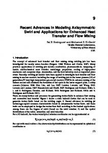
resulting schema is often referred to as a conceptual schema since it describes the main concepts of the application in terms of application entities, their roles and associations. Depending on the model and methodology in use, it may also detail the properties of these entities and also their behavior. A conceptual schema must be adequate in that it captures the relevant features of the application domain. Furthermore, it should be natural in that it should correspond to the sorts of mental models that users form to visualise and work within application domains. The general area of study concerned with the construction of models which correspond directly and naturally to our own conceptualisations of reality is known as cognitive modeling. While the precise nature of mental models is still open to much debate and research, there have been some general principles proposed on the basis of psychological and linguistic research (34). The process of abstraction is fundamental to human information processing and there is strong evidence to support the fact that we make ‘order out of chaos’ by extensive use of classification. We classify individual entities by means of general concepts and then further place these concepts into general classification graphs which relate certain concepts are being specialisations or generalisations of other concepts. Unlike, biological taxonomies, these classification graphs may not be purely hierarchical and an entity may be simultaneously classified in many different ways. For example, in the realm of a company, we could classify persons into customers and employees, and also into males and females. We could further introduce the concepts of female-employees and male-employees since it may be that employment laws require special facilities depending on employee gender and so these concepts are significant in our application domain. The resulting classification graph is shown in Figure 1.2: The nodes are classifications and a directed edge from node n1 to node n2 represents that n1 is a specialisation of n2. A classification graph is generally a directed acyclic graph. It can be considered as modeling the different roles of an entity—and note that an entity may have many roles simultaneously and that these roles may change over time. Thus, a person may be both a customer and an employee and, at some future time, continue to be a customer even though they cease to be an employee.
4
Advances in Object-Oriented Data Modeling
Some roles however may be exclusive and this we can denote by placing constraints over the arcs of a classification graph. For example, in Figure 1.2, we indicate that concept classifications males and females partition persons meaning that every person must belong to exactly one of those classifications. The ability to model entity roles and role-dependent properties and behavior is very important in application modeling and, as we shall discuss later, is something that lacks support in the data models of many existing database management systems. The basis for the classification of an entity may or may not be well-defined. In accordance with a number of contemporary philosophers (26), linguists (18) and psychologists (33), we consider that it may not be possible to define a set of necessary and sufficient conditions for a concept classification. For example, we may not be able to define precisely the concept of a ‘trusted customer’—but we could still choose to classify some of our customers as such. In practical terms, even if a set of defining properties can be established, they may not be of interest in a given information system: We do not need to know anything about the genetic makeup of a person to classify them in males or females. Rather, we may leave the classification to the entities themselves when filling in forms or simply leave it to the end-user who adds an entity representation to a particular classification group during data entry or update. In addition to classification of entities into concepts, we form associations between concepts which allow us to navigate through our information space. Classification structures over associations are also possible. For example, a general association may exist between company employees and customers, and this may be specialised into associations representing various forms of contacts, services and agreements. Conceptual modeling forms the basis for not only the design and documentation of an information system, but also communication between the client and the developer in terms of requirements analysis and contractual agreement. It is the meeting point between the application expert and the method expert and therefore must be easily understood by both, without requiring detailed knowledge of any underlying technology. A schema is defined in terms of a data modeling language associated with the underlying data model. In the case of conceptual schemas, where the focus is on analysis and design, most data models have an associated graphical language which aids understanding through the visualisation of the schema structure. Some data models used for conceptual modeling have only a graphical language, a few have only a textual language—and many have both. Popular data models such as the family of entity relationship models have had many associated graphical and textual languages proposed and these may differ to a greater or lesser extent. An important distinction between data models proposed solely for conceptual modeling and those for data management is that the former generally have no associated operational model since they are used only for system development and not system operation. This difference stems also from the fact that, traditionally, the development of a database has been considered separately from the development of the application programs. Another major goal of object-oriented database technologies
5
1.1
Schema and Model Duality
and methodologies is to consider both aspects of information system development within a common, integrated framework. More recently, there has been a growing trend, as seen in object-oriented analysis and design methodologies (5, 29, 6), to include the modeling of behavior and transactions at the conceptual level. However, we note that, even with such models, a full operational model is usually not supported, since the models are not executable. Where one does see full operational models at the conceptual level, is in the case of prototyping systems which support conceptual modeling (15, 20, 23). Rapid prototyping is generally advocated as a means of eliciting and validating requirements (37, 30). In the software engineering community, rapid prototyping usually revolves around the user interface as a means of determining system functionality and interface design. In contrast, rapid prototyping in the case of information systems development usually revolves around the conceptual schema. Ideally, a rapid prototyping system must support full database functionality in terms of a persistent store, querying, behavior specification and execution, database evolution and constraint management. Fundamental to such a system is a data model which incorporates a full operational model. 1.1.2
Data Models for Data Management
We now turn to consider the requirements of a data model from the point of view of the design and development of a data management system. A data management system is a generalised software system that should provide efficient data management for a range of application systems. It must provide methods of representing, storing and processing data such that operational performance will reach a reasonable standard of efficiency regardless of specific data and application characteristics. This can be done through the provision of a small number of general constructs along with various implementations suited to different data and application profiles. Further, operations on a database should be specified at a logical level which is independent of physical representation and implementation: The system can then determine the methods of evaluation through consideration of data characteristics and the current form of representation. Hence, as the database evolves, the underlying representations and implementations can evolve without recourse to the application programmers or end users. The requirements for efficient data management are in fact not orthogonal to those for conceptual modeling. Both require a data model which provides a small number of general constructs in terms of which one can model the application domain with relative ease. Also, they both require a high-level operational model which is independent of physical representation. We therefore believe that it is possible to realise our goal of a single data model which is both expressive in terms of role and association modeling and provides a good framework for data management (22). In practice, however, many of the designers and developers of database management systems have tended to focus on the level of the storage model or programming language type model as their view of data management. As a result, the system
6
Advances in Object-Oriented Data Modeling
Application Domain Application System Development
DM1
Conceptual Model
••• DMi
Application Interface
SCHEMA
System Interface
DMi ••• System Operation
DMk
Storage Model
Database Figure 1.3 Schema Levels
interface is at too low a level of abstraction and, often, too closely bound to the implementation platform. The schema of a database is thus very much a description of a representation of an application, rather than of the application itself. For example, the relational model which consists of a single generic structure—the relation—may be amenable to an efficient implementation, but is very limited in terms of application modeling as it forces us to model everything in terms of flat tables of values. In the case of most object-oriented database management systems, the constructs and operations of the system interface are basically those of the associated programming language with possibly a few additional generic constructs such as bulk type constructors for sets, lists etc. The problem here is that a programming language type model is designed to model our man-made computer world of values and computations in which everything is well-defined. It is not suited to the sorts of dynamic and flexible role and association modeling required for describing concepts of the application domain. Further, programming languages are often not designed to cater for a persistent environment in which both objects and types can evolve over time (12). 1.1.3
Abstraction Levels
The development and operation of a database system may therefore involve not one, but many, data models as indicated in Figure 1.3. Each data model represents an abstraction level. A schema of one data model will be mapped into a schema of the data model at the level below. Similarly, operations of one data model are implemented in terms of operations at the lower levels. With respect to application system development, an initial conceptual schema may be mapped in one or more stages into a schema defined in terms of the model corresponding to the system interface of the data management system that is the final implementation platform. For example, an entity-relationship schema may be
7
1.2
Evolution of Object-Oriented Models
first mapped into a general relational schema which is then mapped into a schema of specific relational database management system such as the Oracle8 server (4). This schema defines the application interface. A data management system itself usually also involves several abstraction layers— with each layer offering data management services in terms of a set of constructs and operations. Thus, a data management system may have a number of internal data models—including a basic storage model. At the top level is the model which defines the system interface and this is the same model used at the end of the application development process to specify the application interface. It is important to distinguish between data models which are ‘internal’ to system operation and those which are ‘external’ to application development. Those which are internal are of importance only to the developer of the data management system and are not visible to the application programmer or end-user of a database system. To emphasise this, consider the following two cases. First, there is the case of an application developer who uses an object-oriented data model for conceptual design and then maps the resulting schema to a relational schema for implementation. Second, there is the case of the developer of an object-oriented database management system who uses a relational engine for storage management and therefore internally maps the object-oriented data model defining his system interface to a relational model. Is there a significant difference between these two cases since in both a relational system is used to store the data? The important difference between these two cases is that the level of the application and system interfaces is radically different. In the first case, application programmers and direct end-users interact with the database system at the level of the relational schema and must be aware of its structure and operations. In the second case, they interact at the level of the object-oriented schema and the relational schema is purely internal to the system. We consider that our major research goal in the development of object-oriented database systems is not necessarily to remove the different levels of data models, but rather to move the level of the application interface to the conceptual level by providing suitable data models at the system interface which can support both conceptual modeling and effective data management.
1.2
Evolution of Object-Oriented Models From the foregoing discussion, it should be clear that the notion of a data model is central to both information system development and to the provision of general data management services. During the last three decades, a large variety of data models have been proposed. These vary not only in their form, but also in their intended purpose. Many have been proposed specifically as a conceptual modeling tool with the intention that the resulting application model be later translated into the data model of the chosen database management system. Others have been proposed as
8
Advances in Object-Oriented Data Modeling
the basis for a data management service. However, this distinction is not always a clear one as sometimes a data model intended for use as a conceptual modeling tool is later realised in terms of a data management system and an operational part of the model specified. Here we present the main features of a number of data models with the intention of showing how object-oriented data models evolved and how they relate to other kinds of data models. It is beyond the scope of this chapter to provide a comprehensive review of all proposed models—or, indeed, of the model families. We rather simply highlight the main influences and directions of development. Early database management systems were based on the network data model or a restricted version of it known as the hierarchical data model. These models reflect the physical structure of data and are based on the idea of files of records with links between them. Operations are specified at the level of records and a navigational style of programming is supported. Both the structural and operational aspects of these models were criticised for being at too low a level requiring the application programmer to be aware of the physical representation structures and to keep track of navigation through these structures. Although implementations of the relational model were already in existence, the formal introduction of the model is attributed to Codd in his paper (9). The structural part of the relational model represents an application entity as a tuple of values and entity classifications as relations. Associations between entities are implied by cross-references among the values stored in relations. It is interesting to note that in his original exposition of the model, Codd does not state that values must be atomic, but rather introduces it as a secondary restriction that might be appropriate in certain cases. However, the atomicity of values was adopted and considered a basic restriction referred to as the first normal form. The relational model was one of the first data models to have operations at the level of collections and these are given in terms of a relational algebra. The join operator can be used to navigate through the database by means of the associations represented implicitly. The main criticism levelled at the relational model concerns its lack of semantic modeling capability. We can identify two main areas of development of the model aimed at addressing this issue. The first was the need to express conceptual dependencies between relations and the second the need to extend the limited forms of values supported. The notion of keys was introduced to provide some form of entity reference. Crossreferencing of keys is the means of representing associations and linking relations together into a database structure. Concepts of referential integrity were introduced to define the semantics of insertion and deletion operations on a database. The relational model was extended to support further forms of conceptual dependencies so that not only associations between entities, but also associations between classifications such as specialisation relationships could be represented. RM/T (10) extended the relational data model with various metadata relations that described
9
1.2
Evolution of Object-Oriented Models
such dependencies. This model also distinguishes between relations which represent entities from those that represent associations. Proposals for nested relational models remove the first normal form restriction and allow relations as values of attributes. This can be thought of as removing the restriction that the tuple and set constructors can be applied only once and in a specific order—“build tuples and then from these build relations”. By allowing tuple and set constructors to be used repeatedly, we arrive at nested relations. If we further relax the restriction that set and tuple constructors have to strictly alternate, then we end up with what is usually called complex objects (2) or extended relations (25). A number of proposals exist for extending the operational part of the relational model to deal with these complex values: these include (16, 1, 39, 25, 31, 32). Parallel to these developments of the relational model, was the emergence of a number of data models designed specifically to support the conceptual modeling process. We shall refer to these generally as semantic data models since their primary goal was to model application semantics. This family of data models can be considered as having two main influences: The entity-relationship model introduced by Chen (8) and semantic nets introduced in the realm of artificial intelligence for knowledge representation (27, 28). The entity-relationship model was proposed as a database structure design tool and therefore the original proposal had no associated operational model. The model brought to the fore the idea of there being two basic notions of equal importance— entities and associations. The semantic data models which developed from semantic nets took on board the abstractions which were the basis for relationships between concepts—the isa relationship for specialisations and the part-of relationship for aggregation. Smith and Smith (38) proposed to introduce these abstractions into the relational model. From these origins, a number of semantic data models evolved including SDM (14) and TAXIS (19). In these models, entities are represented by complex values and associations as reference attributes. Thus, an association is decomposed into two directional, functional components—usually a dependency between them may be declared in order that consistency is ensured. Later, enhanced entity-relationship models were introduced which combined the basic constructs of the entity-relationship model with the classification structures and complex values supported in other semantic data models. The success of the entityrelationship family of models can be measured by the fact that its use spread into the software engineering community and it strongly influenced current object models used in object-oriented analysis and design methodologies. From this brief description, we see that there was a demand for data models which were more suited to the task of conceptual modeling in terms of modeling application entities, their roles and associations. While the detail and approach of the models varied—in particular, with respect to whether they placed the emphasis on entities, associations or both—the trend was obvious. Data models were required which provided higher levels of abstraction than those provided by existing data management services.
10
Advances in Object-Oriented Data Modeling
Figure 1.4 Evolution of Data Models
One of the key features of these models is that they are entity-based rather than value-based enabling application entities to be modeled directly. Further, the importance of concept specialisation and property inheritance through some form of isa or subtyping relationship was recognised. These are often considered as the essential features of object data models and, if we do so, most semantic data models would nowadays be classified as object data models. The progression of semantic data models to object data models is therefore hard to define in terms of distinguishing constructs. Rather it was a gradual and natural trend which paralleled the new object-based paradigms influencing other areas of computer science. Two papers provide surveys of the first generation of semantic data models. Peckham and Maryanski (24) give a comparative review of a number of semantic data models, while Hull and King (13) examine semantic data modeling concepts through the introduction of a generic semantic data model based on the formal object data model IFO (3). Many object data models for conceptual modeling have been introduced in the last decade. In (21), Mylopoulos discusses the features of many of these and also associated conceptual modeling tools. In Figure 1.4, we show the main evolutionary paths of object data models. On the left, we show data models used primarily for conceptual modeling and on the right those used primarily for data management. The solid lines indicate what we might call ‘positive influences’ on data model development and the dashed lines ‘negative influences’. By this, we mean that a solid line indicates a dependency in which the later model adopted notions from the former model. A dashed line indicates that features were introduced into the later model as a result of inadequacies recognised in the earlier model. Thus, the recognition that the early network and hierarchical models were too bound to physical representation and based on single record-at-a-time processing led to the development of the relational
11
1.2
Evolution of Object-Oriented Models person
Persons partition
customer
Customers
employee
Employees
person
Males
person
Females
Figure 1.5 Role Modeling in Object-Oriented Databases
model. In turn, the lack of semantic expressiveness of the relational model caused people to develop other semantic models that were suitable for conceptual modeling. The right side of Figure 1.4 shows the influences in data model development from the point of view of data management systems. A major influence in recent years is that of object-oriented programming languages and technologies. Motivated by the requirements of advanced applications in the scientific, engineering and commercial domains, the functionality of database systems has been extended to support also the behavioral aspects of information systems in terms of storing programs, rules and integrity constraints alongside data. This has resulted in a new generation of objectoriented database management systems which in turn have influenced relational vendors to add limited object-oriented concepts to their relational systems, see for example Oracle8 (4). Further, these influences are on the increase as more and more developers are choosing object-oriented languages, in particular Java, as their application language. While relational vendors rush to try and integrate object-oriented features into their systems and to support Java language bindings, there still remains a fundamental mismatch in the underlying data models of the relational and object-oriented worlds. This means that an application programmer must continually map between a relational model and the data structures and operations used in his program. Object-oriented database management systems aim for a seamless integration of the database and programming worlds by offering a data model that is compatible with the programming language type model. This means that the constructs and operations that define the data management services interface are compliant with those of the programming language. The type model of the programming language is usually adopted as the model for defining entity representations in terms of object instances. Bulk type constructors—either of the native programming language or introduced through special data management class libraries—are used to represent entity roles by collections of objects. Thus, a part of the classification graph of Figure 1.2 could be represented as shown in Figure 1.5. Here, we denote a collection of objects corresponding to a classification as a rectangle. The shaded part of the collection specifies the types of the objects belonging to
12
Advances in Object-Oriented Data Modeling
Customers
type person ( name : string; phone : set of string; email : string; ..... send_email : ( ) -> ( ) ) type customer subtype of person ( account : string; affiliation : organisation; .......... )
type organisation ( name : string; associates : set of customer; .......... )
Figure 1.6 Types and Collections
that collection. For example, collection Customers is a collection of objects of type customer. The classification Customers is a specialisation of Persons. Thus, each object in Customers is also in Persons. A person may have several roles as represented by memberships of several collections. For example, a male employee who is also a customer would be a member of collections Persons, Customers, Employees and Males. In Figure 1.6, we indicate how such customer objects might be represented in an object-oriented database. The collection Customers is a set of objects of type customer where customer is defined to be a subtype of type person. A customer object therefore has the properties of persons such as name, phone, email and method send_email together with those specific to customers, such as account and affiliation. Some data models clearly distinguish the concepts of entity representation from that of entity classification by having separate constructs. For example, they may use bulk constructors such as set or collection to introduce semantic groupings of objects of a given type. In other models, the two notions are fused into a single class construct which is both a type definition and an implicit grouping of objects of that type. Other models sit somewhere in between. The problem of fusing the two notions is that it prevents multiple classifications of objects of a given type such as Males and Females in Figure 1.5. We would have to instead introduce subtypes, possibly with additional properties, to denote these semantic groupings. A second major difference in the data models of various object-oriented data management systems is the support they give to associations. Some simply represent associations as attribute properties with object references. For example, in Figure 1.6, the attribute affiliation of type customer is a reference to an object of type organization. In turn, an object of type organization has an attribute associates which is a set of references to objects of type customer. If the data model of a system interface provides only this means of representing associations, there is no guarantee of mutual consistency and, further, no special operations or semantics attached to associations. Some systems, such as Objectivity/DB, do recognise two-way associations and also allow special semantics, such as locking or versioning semantics, to be attached to associations. Other systems, for example OMS (17), support a completely separate
13
1.2
Evolution of Object-Oriented Models
association construct with its own algebraic operations and also classification structures. A feature of object-oriented data models that is often used to distinguish them from other data models is their ability to model behavior as well as structure. Objects may have behavioral properties as specified by methods of the associated types. Generally, we find three different uses of methods. First, they may be used to model derived attributes where the values are computed rather than stored. Second, they are used to specify operations or actions associated with an object such as a send_email method on a person object. Third, they are often used to assist navigation through a database by giving direct access to information associated with an object. In such cases, the methods can be thought of as specifying pre-defined queries on objects. For example, a method associated with person objects could be used to directly access the address information of the organizations for which they work. Methods are usually declared separately from their implementation. Thus, the schema may specify only the method signatures in terms of their arguments and results. The implementations of the methods are given elsewhere—either using a general programming language or possibly a special language of the data management system. In fact, a number of so-called object-oriented models have been proposed which deal only with the declaration of method signatures, but not with their implementation or even a behavioral specification. Doing so would appear to underestimate the significance of adding behavior to the database and the need to have means to model and specify this aspect of an information system. One major influence of the relational model concerns query languages and the underlying algebraic model. The introduction of an algebra over collections of tuple values can be considered as one of the main contributions of the relational model. Most object-oriented systems also support some form of algebra over collections of values—but in this case the values are objects rather than tuples. As previously discussed, the ability to model the various roles of application entities and also their associations is central to conceptual modeling. While object data models used for conceptual modeling typically support role modeling (to a greater or lesser extent), it is frequently the case that even the simplest of role models cannot be implemented directly in an object-oriented database system. This arises because their data model is too closely tied to the underlying programming language and, usually, the type system of that language is more restrictive than that of semantic data models. For example, in many object-oriented programming languages, an object could not simultaneously be of type customer and employee and, further, an object cannot change its types—or may only do so in limited ways. Thus, the data models offered by most commercial object-oriented database management systems—and also that of the ODMG standard (7)—tend to be pitched below the abstraction level of conceptual modeling and, as a result, some mapping is required between the structures of the initial application model and that of the final application interface. Further, constraints depicted in classification graphs such as those implied by specialisations or those such as the partition constraint over Males and Females are often not supported and must be implemented by the
14
Advances in Object-Oriented Data Modeling
application programmer. Some support for associations and ensuring referential integrity is supported in the ODMG data model and also in some commercial systems such as Objectivity/DB—but in many others there is no specific support for associations other than being able to represent them through reference attributes as described above. The current situation is therefore that there tends to be two categories of object data models—those developed for conceptual modeling and those developed for data management services as depicted in Figure 1.4. The former focus on semantic expressibility and hence we label them semantic object models. The latter focus on operational aspects and are closely related to the object-oriented programming languages and we label them object-oriented models. To attain our ideal of a truly integrated development framework based on a single data model, we need to combine these two categories and develop a new generation of semantic object-oriented data models. These models will be semantically expressive and at the same time can support efficient data management in an objectoriented programming environment. While efforts in this direction have been made in the research community, many of these ideas have still to permeate into commercial systems.
1.3
Integrating Databases and Programming As described above, one of the major research challenges is to develop objectoriented data models which can support the whole of the database development process from conceptual modeling through to implementation. This requires techniques for resolving the conflict that currently arises between the notions of object and type in conceptual modeling and those of object-oriented programming languages. In programming languages, the major concern is to represent computational values and to do so efficiently by performing static type checking whenever possible. This contrasts with the use of types and values to model application entities, their role dependent behavior and evolution—all of which require dynamic type checking together dynamic binding mechanisms. One solution is to represent object properties associated with roles explicitly rather than through the programming language and variants of this have been proposed for the Smalltalk (11) and Oberon (36) environments. Another solution is to introduce a two-level structure in which database objects are dynamically composed from one of more programming language objects and this is implemented in OMS Java, a data management system and application development framework for the Java environment (35). The integration of behavior into the database presents new challenges to the designers and developers of information systems as it requires new methodologies and tools which seamlessly integrate concepts and technologies from both the software engineering and database communities.
15
1.3
Integrating Databases and Programming
Within the realm of software engineering, various models and methodologies for object-oriented analysis and design have been proposed and are now in widespread use in the Information Technology sector. Of particular note are the OMT (29) and Booch (5) models and methodologies which have been adapted and integrated within the recent UML proposal (6). Such methodologies are not intended primarily for database system development, but rather for the development of large systems of which a database may form a part. Thus the emphasis is more on the development of code and application classes and it is often assumed that database functionality will ultimately be provided by a relational storage system which acts as a form of low-level data repository. Rather than providing an integrated solution which exploits object-oriented technologies to the full, the database is a separate component requiring a mapping between the application and storage models. With respect to application programming, this results in the previously described problems of impedance mismatch where the application programmer must deal with fundamentally different models of data. In the case of information systems, we regard the database as playing a central rather than a subsidiary role. An information architect is responsible for eliciting the information requirements of an enterprise and establishing an information model. These requirements are determined by considering both the structural and dynamic aspects of the information base, application functionality and the characteristics of the information system itself in terms of scope and change. Once this information model has been specified, the development of one or more application systems around it can begin. At issue is how the software engineering point of view can be merged with this database-centred view. For example, rapid prototyping is advocated in both fields— but the focus differs. In the case of software engineering, rapid prototyping is based on the user interface, while, in database development, it is based on the information model. Is it possible to combine these approaches, or should one be preferred? Object-oriented technologies have promised benefits in terms of modularity, reusability and extensibility in application development. Further work is required to realise this potential in terms of information system development. We need to reexamine basic notions such as ‘database’ and ‘schema’ and develop improved models and mechanisms for sharing both metadata and data. In terms of extensibility, it has to be recognised that the ability to extend a data management system for specialised application domains managing temporal, spatial or versioned data has to be supported by full model extensibility. This means that all aspects of a model, and hence of the underlying data management services, have to be extensible. Thus, it should be possible not only to store values of specialised data types, but also to extend the underlying algebra and query language in a natural way. As can be seen from the contributions in this book, these are challenges that are actively being addressed by the research community. In particular, the first part of the book presents proposals for modeling object behavior. A second important dynamic aspect of object-oriented databases is their ability to cope with and represent change both to individual entities of the application domain and to the application domain
16
Advances in Object-Oriented Data Modeling
itself. This aspect is examined in the third part of the book which considers changes to database states and individual object behavior in terms of temporal and dynamic modeling.
References 1. S. Abiteboul and N. Bidoit. Non First Normal Form Relations to Represent Hierarchically Organized Data. In Proceedings ACM SIGACT/SIGMOD Symposium on Principles of Database Systems, pages 191–200. ACM, 1984. 2. S. Abiteboul and C. Beeri. On the Power of Languages for the Manipulation of Complex Objects. (846), 1988. 3. S. Abiteboul and R. Hull. IFO: A formal semantic database model. ACM Transactions on Database Systems, 12(4):525–565, 1987. 4. S. Bobrowski. Oracle8 Architecture. Oracle Press, 1998. 5. G. Booch. Object-Oriented Design with Applications. Benjamin/Cummings, 1991. 6. G. Booch, J. Rumbaugh, and I. Jacobson. Unified Modelling Language User Guide. Addison-Wesley, 1998. 7. R.G.G. Cattell, D. Barry, D. Bartels, M. Berler, J. Eastman, S. Gamerman, D. Jordan, A. Springer, H. Strickland, and D. Wade, editors. The Object Data Standard: ODMG 2.0. Morgan Kaufmann, 1997. 8. P. P. Chen. The Entity-Relationship Model - Towards a Unified View of Data. ACM Transactions on Database Systems, 1(1):9–36, 1976. 9. E. F. Codd. A Relational Model of Data for Large Shared Data Banks. Communications of the ACM, 13(6):377–387, 1970. 10. E. F. Codd. Extending the Database Relational Model to Capture More Meaning. ACM Transactions on Database Systems, 4(4):397–434, 1979. 11. G. Gardarin, B. Finance, and P. Fankhauser. Federating Object-Oriented and Relational Databases: The IRO-DB Experience. In Proc. 2nd Intl. Conf. on Cooperative Information Systems CoopIS 97. IEEE Computer Society Press, 1997. 12. G. Gottlob, M. Schrefl, and B. R¨ocki. Extending Object-Oriented Systems with Roles. ACM Transactions on Information Systems, 14(3), July 1996. 13. R. Hull and R. King. Semantic Data Modeling: Survey, Applications, and Research Issues. ACM Computing Surveys, 19(3):201–260, 1987. 14. M. Hammer and D. McLeod. Database Description with SDM: A Semantic Database Model. ACM Transactions on Database Systems, 6(3):351–386, September 1981. 15. M. Jarke, R. Gallersd¨orfer, M. A. Jeusfeld, M. Staudt, and S. Eherer. ConceptBase - A Deductive Object Base for Meta Data Management. Journal of Intelligent Information Systems, 4(2):167–192, 1995.
17
References 16. G. Jaeschke and H.-J. Schek. Remarks on the algebra of non-first-normal-form relations. In Proceedings ACM SIGACT/SIGMOD Symp. on Principles of Database Systems, pages 124–138, 1982. 17. A. Kobler, M. C. Norrie, and A. W¨urgler. OMS Approach to Database Development through Rapid Prototyping. In Proc. 8th Workshop on Information Technologies and Systems (WITS’98), Helsinki, Finland, December 1998. 18. G. Lakoff. Women, fire, and dangerous things. What categories reveal about the mind. University of Chicago Press, 1987. 19. J. Mylopoulos, P. A. Bernstein, and H. K. T. Wong. A Language Facility for Designing Interactive Database-Intensive Systems. ACM Transactions on Database Systems, 5(2):185–207, June 1980. 20. M. Missikoff and M. Toiati. MOSAICO – A System for Conceptual Modelling and Rapid Prototyping of Object-Oriented Database Applications. In Proceedings of the 1994 ACM SIGMOD International Conference on Management of Data, page 508. ACM, 1994. 21. J. Mylopoulos. Information Modeling in the Time of the Revolution. Information Systems, 23(3 & 4), 1998. 22. M. C. Norrie and A. W¨urgler. OM Framework for Object-Oriented Data Management. INFORMATIK, Journal of the Swiss Informaticians Society, (3), June 1997. 23. M. C. Norrie and A. W¨urgler. OMS Rapid Prototyping System for the Development of Object-Oriented Database Application Systems. In Proc. Intl. Conf. on Information Systems Analysis and Synthesis, Orlando, USA, August 1998. 24. J. Peckham and F. Maryanski. Semantic Data Models. ACM Computing Surveys, 20(3): 153–189, September 1988. 25. P. Pistor and Traunmuller. A database language for sets, lists, and tables. Information Systems, 11(4):323–336, December 1986. 26. H. Putnam. Is Semantics Possible? In P. Schwarz, editor, Naming, Necessity, and Natural Kinds. Cornell University Press, 1977. 27. R. Quillian. Semantic Memory. In M. Minsky, editor, Semantic Information Processing. MIT Press, 1968. 28. B. Raphael. A computer program for semantic information retrieval. In M. Minsky, editor, Semantic Information Processing. MIT Press, 1968. 29. J. Rumbaugh, M. Blaha, W. Premerlani, F. Eddy, and W. Lorensen. Object-Oriented Modeling and Design. Prentice Hall, 1991. 30. M. Ryan and A. Doubleday. Evaluating ’Throw Away’ Prototyping for Requirements Capture. In Proc. 3rd World Conference on Integrated Design and Process Technology, Berlin, Germany, July 1998. 31. M. A. Roth, H. F. Korth, and D. S. Batory. SQL/NF : A Query Language for ¬ 1NF Relational Databases. Information Systems, 12(1):99–114, March 1987.
18
Advances in Object-Oriented Data Modeling 32. M. A. Roth, H. F. Korth, and A. Silberschatz. Extended Algebra and Calculus for Nested Relational Databases. ACM Transactions on Database Systems, 13(4):389–417, December 1988. 33. E. Rosch. Cognitive representations of semantic categories. Journal of Experimental Psychology: General, 104:192–233, 1975. 34. N. A. Stillings, M. H. Feinstein, J. L. Garfield, E. L. Rissland, D. A. Rosenbaum, S. E. Weisler, and L. Baker-Ward. Cognitive Science: An Introduction. MIT Press, 1991. 35. A. Steiner, A. Kobler, and M. C. Norrie. OMS/Java: Model Extensibility of OODBMS for Advanced Application Domains. In Proc. 10th Conf. on Advanced Information Systems Engineering (CAiSE’98), Pisa, Italy, June 1998. 36. J. Supcik and M. C. Norrie. An Object-Oriented Database Programming Environment for Oberon. In Proc. of the Joint Modular Languages Conference (JMLC’97), Linz, Austria, March 1997. 37. A. G. Sutcliffe and M. Ryan. Experience with SCRAM, a SCenario Requirements Analysis Method. In Proc. 3rd IEEE Intl. Conf. on Requirements Engineering, Colorado, USA, April 1998. 38. J. M. Smith and D. C. Smith. Database abstractions: Aggregation and generalization. ACM Transactions on Database Systems, 2(2):105–133, 1977. 39. H. J. Schek and M. H. Scholl. The Relational Model with Relation-Valued Attributes. Information Systems, 11(2):137–147, June 1986.
I
Behavioral Modeling
This page intentionally left blank
2
A Behaviorally Driven Approach to Object-Oriented Analysis and Design with Object-Oriented Data Modeling Lois M. L. Delcambre Computer Science & Engineering Department Oregon Graduate Institute P.O. Box 91000 Portland, OR 97291-1000 [email protected] Earl F. Ecklund OBJECTive Technology Group Beaverton, OR 97008 [email protected] This paper presents a behavioral approach to object-oriented analysis and design and compares it to a structural approach. The difference between these two approaches is most apparent during the analysis phase of software development when the first object model is selected. Our behavioral approach is use case-driven during analysis: objects are selected and responsibilities are assigned to objects precisely because they are needed to support the behavior of one or more use cases. The contribution of this paper is the detailed description of issues that should be considered and issues that should not be considered during analysis and during design. This paper also discusses several open issues in object-oriented data modeling, regardless of whether a behavioral or structural approach is used.
2.1
Introduction When software is developed using objects, the software system is modeled as a set of objects with each object an instance of a class. A class1 defines the messages that can be sent to an object with the corresponding signatures, the attributes to be represented in the object, and the associations between objects of this class
1. This is more precisely a type; we use the term class as in OMT.
22
A Behaviorally Driven Approach to Object-Oriented Analysis Table 2.1 Comparison of OMT and our Behavioral Approach to Analysis
Starting point: Motivation for objects: Motivation for connecting objects: Resulting object structure: Results:
Object Modeling Technique (OMT) (22) Concepts/structure in the real world Objects of interest in the real world Associations of interest in the real world Detailed structure using many structural constructs and constraints Good characterization of how individual objectgs respond to events
Disciplined OO Software Engineering (DOOSE) Use cases (behavior required by users) Objects to support responsibilities for a use case An object that must invoke a responsibility of another object (a collaboration) Classes, responsibilities, & collaborations (without explicit attributes or associations) Good characterization of how a group of objects collaborate to support a use case
and other objects (of this class or a different class). The software system executes by sending messages to objects. A message to an object invokes the relevant method, which may send messages to other objects, etc. The implementation of objects is encapsulated. That is, the internal data structures and the method bodies are not visible to other objects. The choice of classes, the attributes of classes, and the associations among classes is sometimes called an object-oriented data model.2 An object model sets the structure of the software system; at the same time, an object model must include all behavior required of the software system. How can the object model be developed? One popular approach (22) focuses first on the structure of objects based on concepts in the real world of interest to the application. We take a different approach, focusing on the desired behavior of the system as expressed in a set of use cases (17). These two approaches are contrasted in Table 2.1. The difference between these two approaches is most evident during analysis when the first object model is constructed. The Object Modeling Technique (OMT) (22) recommends that the object model be defined first, with an emphasis on representing objects (and attributes and associations) that correspond to concepts of interest in the real world. The second step is to model each object that has interesting states along with the events that cause state transitions, in a state diagram, based on statecharts (14). Cook and Daniels have described a similar approach more recently (5).
2. An object-oriented data model also includes other, more advanced constructs such as aggregation, composition, and generalization among objects as well as more detail such as attribute types, multiplicity of associations, etc.
23
2.1
Introduction
Our approach focuses first on the desired behavior of the software system by describing use cases3 (17). Each use case describes one interaction with a software system from the point of view of an actor. Each actor represents a class of users (such as booking clerk, branch manager, etc. for a car rental application). The scenario of the use case describes how the system must perform, i.e., the desired behaviors of the system to be built. The objects can be discovered using a responsibilitydriven approach (26) based on CRC (class-responsibility-collaboration) cards (1). A responsibility for an object is something that the object must “do” or must “know.” Collaboration is when one object sends a message to another object, to receive some assistance to perform the currently invoked responsibility. We refer to our approach as Disciplined Object-Oriented Software Engineering (DOOSE) (6, 7) because of our focus on work products from one step driving the next step and our requirement for traceability among the work products. These approaches differ in their central focus. OMT produces a richly structured object model that describes objects, attributes and associations that occur in the real world to which methods can be added. Our approach is driven by the desired behaviors of the system. The resulting object model represents a set of responsibilities and collaborations that will support the complete set of use cases. We focus on a behaviorally driven approach to object-oriented development because we believe that the resulting software is more likely to reflect the needs of the application. We also believe that it is valuable to focus on the responsibilities and collaborations of objects early in the development lifecycle (rather than associations, attributes, and methods) because it provides a more abstract view of objects. However, we must find a way to include the object-oriented data modeling necessary to complete the object model. The contribution of this paper is the identification of which aspects of data modeling should be included (and excluded!) from the analysis step and which aspects of data modeling should be handled during design. This paper also introduces the concept of the shared model to guide the developer as to what should be included and excluded in the use case and analysis models. Regardless of the object-oriented analysis and design method used, we might wonder whether object-oriented software requires a “database design” step, much like traditional database design, in order to model the persistent data in a way that meets the needs of multiple applications and that provides reasonable performance. Should we take the object model for the software system, perhaps discovered using a behaviorally oriented approach, as the basis for our (object-oriented or other) database schema? One could argue that object-oriented databases set out to eliminate the need for database design. Because they support persistent C++, Java or Smalltalk, it is possible to take classes from the software model and simply make them persistent. We believe that such an approach, although possible, is naive.
3. There is, however, a domain glossary developed in conjunction with the use case model to define concepts from the domain.
24
A Behaviorally Driven Approach to Object-Oriented Analysis
Database design is a necessary step for several reasons (18). (1) The attributes and data structures of a class required to support the software might not be exactly the attributes and data structures that are to be stored persistently. We may need only a subset of the attributes and data structures to be stored persistently. (2) We may need more than one collection (e.g., set, list, bag, array) of objects of a particular type (class). Thus it is inappropriate to assume that there is a single set of all instances of a given class. (3) Databases typically define a global name space, including such things as table names, attribute names, etc. For objects, we may need persistent “handles” or names for objects that serve as entry points into the persistent data. (4) We may need individual objects that are persistent by themselves, without being in a named collection. Such objects may have the kind of handle mentioned in point (3). (5) Database design requires information about how many instances are likely for each collection, in order to decide about clustering, indices, etc. Such information is typically unavailable in an object model for software. In the remainder of this paper, we give a brief description of our behavioral approach using an example from the EU Car Rental application in Section 2.2. This is followed by a discussion in Section 2.3 of how to do object-oriented data modeling in this method. Related work is presented in Section 2.4. The paper concludes in Section 2.5 with a brief discussion of open issues with regard to object-oriented data modeling.
2.2
DOOSE Object-oriented Analysis and Design—Example In this section, we give a quick overview of our approach to object-oriented analysis and design by developing a portion of the Use Case, Analysis, and Design Models for the EU-Rent Rental Car example (23). We begin by developing the Use Case Model, starting by identifying the scope of the system under development (setting the system boundary), the actors (roles) that interact with the system, and the “original” use cases. For the EU-Rent case study, we identified 11 actors and 46 original use cases, shown in Table 2.2. For each use case, we develop a scenario, often in the form of a conversation (25) between the actor and the system. The scenario reflects the normal course of execution for the use case (17). We also indicate alternatives, where conditional or exceptional situations require revisions to the scenario. We refine the use case model to eliminate redundant portions of scenarios by factoring them into separate use cases. This brings us to the refined use case model. A UML use case diagram of the refined use case model for the actor Booking Agent is shown in Figure 2.1. Since a complete refined use case diagram for the system is often quite large, we may draw several use case diagrams where each diagram shows the use cases that pertain to one actor. We see the uses and extends relationships between refined use cases. uses indicates that one use case (the client at the tail end of the arrow) uses the other (at the head end of the arrow) as part of the client’s scenario. That is to say that the client’s scenario would be incomplete without
25
2.2
DOOSE Object-oriented Analysis and Design—Example
Table 2.2 Original Use Cases for EU-Rent Case Study Branch Offices Actor: Booking Clerk 1. Accept rental return 2. Process late return 3. Report on late rental returns 4. Extend rental for late rental returns 5. Process rental 6. Take rental reservation 7. Cancel rental reservation Actor: Branch Manager 8. Extract next day’s reservations 9. Transfer cars out 10. Cancel transfer out 11. Transfer cars in 12. Manage car pool 13. Write off car 14. Purchase cars 15. Sell cars 16. Report on car conditions 17. Service cars 18. Produce booking report 19. Run rental report Actor: Storage Lot Staff 20. Confirm rental preparation
Corporate Head Office Actor: Director 21. Maintain car groups 22. Set rental tariffs (rates) 23. Set branch purchase budgets 24. Assign branches to service depots Actor: Clerk 25. Maintain blacklist 26. Maintain branch information Actor: Loyalty Incentive Clerk 27. Mail member statements 28. Process awards/ vouchers 29. Maintain membership 30. Compensate branch for award rental
Actor: Purchasing Agent 31. Contact for purchases 32. Pay for new cars 33. Receive payment for used cars
Service Depots Actor: Depot Clerk 34. Accept service drop off Actor: Maintenance Foreman 35. Service car Actor: Depot Manager 36. Schedule service 37. Write off damaged car 38. Contract out service 39. Allocate drivers for next day 40. Maintain service history 41. Report on cars requiring service 42. Run report on current week activity summary Other
Actor: Driver 43. Pick up car (transfer) 44. Pick up car (service) 45. Deliver car (transfer) 46. Deliver car (service)
the “used” use case’s scenario steps. uses links occur when common scenario steps are factored into a separate, shared use case. extends indicates that the extending use case (at the tail end of the arrow) creates an (optional) extended scenario by adding its own scenario steps to the scenario of the extended use case. The extended use case’s scenario is complete in its own right and it may also be extended. extends often indicates that the extending use case contains conditional or optional behavior, associated with alternatives of the extended use case. We use a numbering style for the refined use cases that is intended to hint at the traceability information in the refined use case write-up (e.g., see “Traces to” in Figure 2.2). Original use cases that are un-factored in the refined use case model
26
A Behaviorally Driven Approach to Object-Oriented Analysis
Booking Clerk
7 Cancel Reservation
4 Extend Rental 106 Take Reservation
102 Process Late Return
105 Process Rental 101 Accept Rental Return
201 Calculate Charge
203 Charge Credit Card
202 Process Return
3 Report on Late Returns
205 Process Damage Claim
206 Update Service Records
204 Transfer Car Owner
Figure 2.1 Refined Use Cases for Booking Clerk in EU-Rent Case Study
retain their original numbers, such as use cases 3, 4 and 7 in Figure 2.1. Use cases numbered in the 100’s are the refined use cases that correspond to original use cases; they are numbered 100 plus the number of the corresponding original use case, e.g., refined use case 106 provides the main actions of use case 6. Refined use cases numbered above 200 are new use cases introduced in the use case refinement process. For example, use case 201 Calculate Charge, is used to estimate the rental charge during the reservation process and the rental process (to pre-authorize the credit card charge), as well as to calculate the actual charge during the rental return process. Refined use cases 106 and 201 comprise the original use case 6. Refined use cases that appear for more than one actor are shown with shaded ovals. For example, use case 204 also appears in the refined use case diagram for the actor Branch Manager, where it is used by use case 111 Transfer Cars In (which refines use case 11). We advocate incremental and iterative software development. An increment is a set of functionality4 that is to be developed, implemented and tested (and optionally deployed) as a unit. Thus, each increment involves a full iteration of the “lifecycle”
4. In DOOSE, an increment is defined as the requirements and the set of use cases to be developed in one iteration of the development process.
27
2.2
DOOSE Object-oriented Analysis and Design—Example
Use Case 106. Take rental reservation Actor: Booking Clerk Purpose: Validate customer and create reservation for specified car group on specified date. Other Actors: Traces to: Use Case 6, Use Case 5 Preconditions: Scenario: 0) Clerk answers phone and receives request for reservation. Clerk obtains customer’s identification (drivers license number) and age. Clerk enters customer’s identification (drivers license number). 1) System determines that customer is not blacklisted. 2) System displays reservation interface containing customer info, preferred car group and car group rate (from customer records and tariff policy), this branch as pickup site with tomorrow’s date and 8:00 AM as default date and time of rental, and this branch as return site with tomorrow’s date and 6:00 PM as default date and time of return. 3) Clerk enters and edits requested car group, place, date and time of pickup, place, date and time of return, 4) System invokes Use Case 201 to estimate total cost of rental 5) Clerk verifies all terms, quotes estimated cost to customer, and confirms reservation. 6) System commits reservation record info and displays confirmation record locator number. 7) Clerk reads confirmation record locator number to customer Postconditions: Reservation record for specified rental date, car group, and branch is created. Alternatives: Step 0: Reservation may also be made by mail or by walk-in customer. If customer is under 21 years of age, reservation is refused and use case is exited. Step 1: If customer is blacklisted, reservation is refused, and use case is exited. Step 5: If customer declines reservation, use case is exited. Comments: Figure 2.2 Refined Use Case for Take Reservation in EU-Rent Case Study
of software development activities. Each increment begins with a selection of use cases from the refined use case model. The refined use case model serves as the input to the analysis step; that is, our object-oriented analysis is use case-driven (16, 17). Each use case in the refined use case model is written in detail, as shown in Figure 2.2. By following the scenario, we identify the object instances (and, thus, their classes), the responsibilities, and the collaborations needed to perform the scenario. For example, from steps 0 and 1 of Use Case 106 (Figure 2.2), we decide that there should be customers (Customer class), a collection of all customers (Customer Collection class) with the responsibility to lookup customer by drivers license number, and that class Customer should have the responsibility to “know if blacklisted”.
28
A Behaviorally Driven Approach to Object-Oriented Analysis
Take Reservation Control
Take Reservation Interface
Customer Collection
Customer
Rental Terms
Estimate Rental Charge Control
get Customer Id
lookup Customer
know if on Blacklist get Rental Terms know Car Group preference and Discount Group preference set Rental Terms
estimate Rental Charge [Use Case 201]
confirm Reservation
Reservations
create Reservation
know Reservation
return Reservation number
Figure 2.3 Analysis Sequence Diagram for Use Case 106 Take Rental Reservation
Responsibilities are assigned to objects precisely because they are needed to perform the scenario for one (or more) use cases. Thus, although we anticipate that Customer will also have the responsibility to “know drivers license number”, we do not need to ask the customer object for this information in this scenario, so we defer adding this responsibility until it is required. The UML Sequence Diagram is an effective mechanism to record the objects, responsibilities and collaborations required to support a use case. The sequence diagram for Use Case 106 Take rental reservation is shown in Figure 2.3. As analysis proceeds through successive use cases, we gather, for each class, all the responsibilities and collaborations pertinent to that class. We use the CRC process of discovering objects and responsibilities during analysis (1, 24, 26). The emerging object model can be recorded on the CRC cards. When the analysis activity is complete, the collected responsibilities of each class are shown in the UML Class Diagram of the Analysis Object Model. A partial class diagram (restricted to only analysis objects) is shown in Figure 2.4; for brevity, we show the class diagram after the Take Reservation and Process Rental use cases have been analyzed. The analysis object classes Take Reservation Control, Take Reservation Interface, Estimate Rental Charge Control, Process Rental Control, and Process Rental Interface are omitted for simplicity. These interface and control objects have straightforward responsibilities and no associations. Note that the dashed lines shown
Rental Terms set Rental Terms know Car Group know pickup Branch know pickup date know pickup time know scheduled return Branch know actual return Branch know return date know return time know Discount Group
Credit Card know type of Credit Card know Credit Card number know expiration date know name on card
Figure 2.4 Analysis Class Diagram for EU-Rent Case Study after two Use Cases
in Figure 2.4 simply represent the responsibilities to “know” another object in a graphical manner. Using responsibilities rather than attributes hides the implementation mechanism. For example, Customer has a responsibility to “know if on Blacklist” which could be implemented as a query function against a Blacklist database or data structure, or as a Boolean attribute of Customer. During analysis, these implementation choices are secondary to capturing the behavior that requires a customer to know whether it is or is not blacklisted. Customer also has a responsibility to “know Reservations.” We may choose to design a “get Reservations” method that returns a set of Reservations as a collection object, or we may choose to scan the Reservations collection using an Iterator object. Decisions like these are intentionally deferred until design. We use the analysis model as input to the design phase. Each class must be designed, private data structures selected, method names and signatures set, etc. during the design phase. The design process is responsibility-driven; design proceeds by considering classes, one at a time, and by designing each responsibility for the class. As an example of how we do design, the final design for the RentalRecord class is shown in Table 2.3. Here we assume that C++ is the implementation language. The notation shown uses ’-’ and ’+’ as visibility markers on the attributes and operations, to express private and public, respectively. Note that in this example, most of the classes mentioned were introduced in the Analysis Model, however we do find helper objects introduced to support the design, such as the ReturnCode class, which is designed to be an enumerated type. We also see that the responsibility to create Rental Record has been designed as the class constructor and has been overloaded to allow Rental Records to be created with either the vehicle supplied or left null to be assigned later (using the “assignVehicleToRentalRecord” operation).
30
A Behaviorally Driven Approach to Object-Oriented Analysis Table 2.3 Design Class for RentalRecord Class in EU-Rent Case Study Rental Record - customer: Customer∗ - vehicle: Vehicle∗ - rentalTerms: RentalTerms∗ - creditAuthorization: CreditAuthorization∗ + RentalRecord(Customer∗ customer, Vehicle∗ vehicle, RentalTerms∗ terms, CreditAuthorization∗ auth): RentalRecord + RentalRecord(Customer∗ customer, RentalTerms∗ terms, CreditAuthorization∗ auth): RentalRecord + ∼RentalRecord(); + assignVehicleToRentalRecord(Vehicle∗ vehicle): ReturnCode + getCustomer(): Customer∗ + getRentalTerms(): RentalTerms∗ + getCreditAuthorization∗ + getVehicle(): Vehicle∗
2.3
Object-Oriented Data Modeling during Analysis and Design This section articulates the main goals and activities for the analysis step and the design step of our object-oriented software development method. This section also discusses how object-oriented data modeling fits into this approach. In particular, we describe how object-oriented data modeling is handled during analysis and how it is handled during design. One question that arises when a development method includes both analysis and design activities is: how do you know when to stop analysis? When is analysis becoming too detailed? Or conversely, how do we keep the use case model as well as the analysis model from becoming too shallow, e.g., by focusing only on the user interface details? In general we are guided by the principle of the “shared model.” The shared model (8) is the understanding of the system to be developed that is shared between the actor(s) and the system. The shared model for a use case comprises the actor’s understanding of what the system is doing. As an example, the Booking Clerk knows that the system computes the estimated charges for a reservation. Each use case has its own shared model, based on the actor’s understanding of the use case processing. The shared model during analysis represents the collective, unified shared model for all use cases. The notion of the shared model helps us articulate what to include and exclude for the use case model and the analysis model. We say that an object or a responsibility belongs in the analysis model precisely when it is in the shared model. In other words, the use case model and the analysis model should include precisely that which is visible and meaningful to the users.
31
2.3
Object-Oriented Data Modeling during Analysis and Design
Table 2.4 Analysis: when the implementation and deployment environment is not considered. Activities and Goals
Support for Object-Oriented Data Modeling
2.3.1
1. Select objects, responsibilities and collaborations. 2. Be use case-driven. 3. Be complete. (Analyze all use cases in current increment.) 4. Recognize UI design as a separate, valuable, perhaps parallel activity. 5. Use well defined terms, e.g., from a glossary. 1. Introduce responsibilities of objects to “know” certain things. 2. Identify objects that must be remembered. (persistence). 3. Identify objects that collaborate. (This is a potential navigation path.) 4. Introduce collection objects (or other information structures) to support searching for objects in the collection, etc.
Analysis—with object-oriented data modeling
The activities and goals of the analysis step are listed in the top portion of Table 2.4. Analysis is when the first object model is discovered through the selection of objects and responsibilities that are understandable to the domain experts or the actors. Our approach to analysis is use case-driven, as shown on the second line of Table 2.4. This means that we require the identification of significant use cases to serve as input for analysis. More than that, it means that we select objects only when they are needed to support one or more use cases. When the first use case is considered, we introduce as many objects as we need. For the second and subsequent use cases, we may introduce new objects; we may introduce new responsibilities for existing objects; or we may reuse existing objects and responsibilities. Similarly, we assign a responsibility to an object only when it is needed to support one (or more) use cases. Thus analysis is literally driven by the behavioral requirements of the system. We believe that analysis should be complete, with respect to the given set of use cases, as shown in the third line of the top half of Table 2.4. Said another way, we believe that the analysis object model (i.e., the selected objects and responsibilities) represents the cumulative load or cumulative demand on the objects from the complete set of use cases for the current iteration. It is often the case that the statement of individual responsibilities has been generalized during the course of analysis. The first time a responsibility is conceived, it reflects the needs of a single use case. As the responsibility is used a second or third or nth time, the statement of the responsibility may be more general. This process of generalizing responsibilities (while they are still described simply as a phrase in natural language) is one of the chief advantages of this form of analysis. In a similar vein, we might decide that our choice of objects can be refined or simplified based on what we’ve learned from the use cases considered so far.
32
A Behaviorally Driven Approach to Object-Oriented Analysis
Any software system with human actors will require some form of user interface. We concur with Jacobson (17) that sketching out a user interface can assist with the development of the use case model. However, the actual user interface design, based on aesthetics and other issues, is separate from elaborating the way that the software system must work, as shown in the fourth line of the top portion of Table 2.4. Because the use case model and the analysis model are both expressed in natural language, it is important to be precise about terms and concepts from the application domain and how they are defined. If standards exist, e.g., through an existing glossary, they can be used directly. The glossary allows us to be precise about concepts from the domain without requiring that the domain concepts appear in the object model. The use of a glossary is listed on line 5 of the top half of Table 2.4. We believe data structures as well as the detailed structure of the object model should be developed during design. But we need to represent the data required for the application in the analysis model. The bottom half of Table 2.4 describes how we represent data in our analysis model. If data is present in the system, then it is represented as the responsibility for one object to “know” something as shown in the first line in the bottom half of Table 2.4. As an example, we expect the Customer object in the EU-Rental system to “know driver’s license number.” Similarly, we might expect a Reservation object to “know customer” who has made the reservation. We intentionally model what might be represented as attributes and what might be represented as associations with this single construct - a responsibility “to know.” The duality of values and objects and the associated duality of attributes and associations motivates our choice. A booking clerk can have the responsibility “to know the branch office” whether the branch office is modeled as a value or as an independent object. We can add the branch office object as a separate analysis object, if we need it, without the overhead of transforming all the attributes to associations. The persistence of data beyond the execution of a program is an issue that will be mainly addressed during design, e.g., influenced by the choice of a database management system or other technology. Should the persistence of data be modeled during analysis? As usual, we answer this question based on the answer to the question “is it in the shared model?”. Some persistence is clearly visible to the actors. The booking clerk expects that reservations made yesterday will still be “in the system” today. Such user-visible persistence should be modeled during analysis. See the second line in the bottom half of Table 2.4. There may also be persistent data that is an artifact of the design. For example, we might design a logging process for recovery purposes. The log contents would likely not be user-visible. All classes shown in Figure 2.4 are persistent at the analysis level. (Note that the control objects and interface objects, not shown in Figure 2.4, are not persistent.) The decision about who to collaborate with and when to collaborate is made during analysis. In fact, decisions about collaboration are at the heart of the analysis process along with the selection of objects and responsibilities. We believe that it is appropriate to decide what collaborations are needed during analysis but inappropriate to decide how the collaboration might be supported. In effect, collaboration requires
33
2.3
Object-Oriented Data Modeling during Analysis and Design
that the collaborator be “known” to this object. But how it comes to be known (e.g., through an association that is persistent or by receiving a parameter that references the other object) is a decision that should be made during design. Thus we see the identification of collaborations during analysis but no identification of associations as shown in the third line of the bottom portion of Table 2.4. Whenever there are multiple objects grouped together, then we may wish to search for objects in the group. Who should have the responsibility to search, e.g., for a customer based on the customer’s name? In order to search for an object, we must have a collection or container holding multiple objects. We use the term collection here as an abstract term to represent any container of objects. It might be implemented as a list, a linked list, an array, a B+-tree, a database table, etc. Such implementation choices will be made during design. At this stage during analysis we need only introduce a collection object such as CustomerCollection. It is quite natural then for the collection object to have a responsibility “to lookup customers.” The use of collection objects during analysis is shown on the fourth line in the bottom half of Table 2.4. 2.3.2
Design—with object-oriented data modeling
Design begins with the identification of the implementation and deployment environment. The analysis model is characterized by what is visible in the shared model. Design is characterized by how things will be accomplished in the implementation and deployment. Design is done by considering each class in turn, as shown in the first line in Table 2.5. For each responsibility of a class, we must decide on the data structures needed as shown in the second line of Table 2.5. Data structures are required to support the responsibilities to “know,” to hold the arguments for methods, and for any data required for the design. We must also decide on the signature(s) for each method as shown in the third line of Table 2.5. We do so based on the statement of the responsibility from the analysis step and on the other data structures present in this object. The most general signature is generally described first, followed by any overloaded signatures. The overloaded signatures often leave out certain input parameters. These parameters then take on a default value and the more general method is called. Throughout the design process, we must be systematic. We must make sure that objects exist when they need to exist (that is that all objects are created, as needed), that objects are “known” by some means when collaboration occurs, and that all alternatives and exceptions are handled. These issues are shown on lines 4, 5, and 6 of Table 2.5. These issues were intentionally ignored during analysis, unless they appear in the shared model.5 The first of these two should be addressed whenever we
5. See for example the responsibility to create Rental Record for the Rental Record class in Figure 2.4.
34
A Behaviorally Driven Approach to Object-Oriented Analysis Table 2.5 Design: when the implementation and deployment environment is considered. Activities and Goals
1. Be class/responsibility-driven. 2. Design data structures to hold data visible in analysis (with the responsibility to “know” something) plus data needed for the design. 3. Select method signatures (including overloaded signatures). 4. Make sure all objects are created as needed. 5. Make sure that all objects needed for collaboration are “known” to the calling object. 6. Systematically consider all alternatives and exceptions. 7. Introduce design objects (i.e., “helper” objects) as needed. 8. Use patterns (e.g., for “hot spots” that need configurability or flexibility). 9. Decide on class hierarchy.
Support for Object-Oriented Data Modeling
1. Handle persistence (from analysis plus additional persistence). 2. Introduce persistent relationships, as needed. 3. Design the database (with queries/navigation in mind). 4. Handle transactional aspects including recovery, redundancy. 5. Design the interface between the object model and the DB.
invoke a responsibility. In order to invoke a responsibility, we must send a message to the appropriate object. And in order to send a message to an object, the object must exist and we must have a reference to that object. The third issue concerns alternatives and exceptions that must be addressed to complete the design of this object. The alternatives may have been identified during the development of the use case model and listed at the bottom of each use case scenario, as in Figure 2.2, or they may be added during design. Design is when additional objects are introduced to support the implementation as, indicated on line seven of Table 2.5. For example, a complex data structure, such as a list or a binary tree, might introduce one or more objects. Such design objects might be available from a component library (19). Such objects are in the domain of the implementation and are generally not user-visible, i.e., they are not in the shared model. The use of design patterns (11) may also introduce additional objects into the design, as shown on line eight of Table 2.5. Each design pattern provides flexibility or configurability in one dimension. Wolfgang Pree (20) has introduced the term “hot spot” for any part of your design that is likely to change. It is appropriate to consider using a design pattern for a hot spot provided that the pattern introduces the kind of flexibility or configurability that matches the expected changes. Once the data structures and method signatures emerge for the design objects, it is appropriate to finalize the class hierarchy. Shared responsibilities, attributes, and
35
2.4
Related Work
associations can be factored out into a superclass. It is also the case that a design pattern may introduce certain class/subclass relationships. The support for data modeling during object-oriented design is shown in the bottom half of Table 2.5. During design, all of the details about data structure, persistence, associations, external file or database system, queries, and transactions are considered and finalized. It is during design that an appropriate mapping from the object model (that comprises the software system) to the persistent objects or entities must be defined. This mapping is influenced by the choice of the implementation and deployment environment. A recent book by Blaha and Premerlani has a detailed exposition of how a design object model can be mapped to various file systems and database management systems (2).
2.4
Related Work The current state of object-oriented development methods reflects a synthesis of ideas from a number of methods. Use cases are advocated by many authors beyond their original inventor as evidenced by their appearance in the Unified Modeling Language (UML) (13). State diagrams are widely acknowledged to be useful to describe objects with complex state, particularly where the stimuli to the system can be successfully modeled using events (12). Fusion (4) is a self-proclaimed “second generation” method for object-oriented development precisely because it “fuses” ideas from other methods. Fowler (10) sketches a method (with variations) that includes many of the UML diagrams as work products including use case diagrams, class diagrams, state diagrams, etc. Approaches to Object-Oriented Analysis can be classified into behaviorally oriented, operationally oriented, and data-oriented. Our approach is behaviorally oriented, as is the Object Behavior Analysis approach of (21) and the ResponsibilityDriven Design of (26). We feel that analysis with a behavioral focus, where everything is represented as a responsibility, is at a higher, more abstract level than the other approaches. We also feel that behavioral modeling with a use case-driven approach, is less subject to scope creep, in that objects and responsibilities are discovered as needed, rather than identified in anticipation of being required in some unknown, yet to be identified, future collaboration. The operationally oriented approach can be characterized as identifying the operations needed to support the application, forming interfaces that collect cohesive sets of operations, and associating each interface with an object class that will own those operations as its responsibilities. Operationally oriented analysis strikes us as a bottom-up approach to modeling behavior, although it may lead to early identification of interfaces useful for reasoning about system architecture. We would describe the Fusion method (4) as operationally oriented. Data-oriented approaches are, in fact, extending the entity-relationship-style of modeling (3) to object-oriented development. Data-oriented approaches include
36
A Behaviorally Driven Approach to Object-Oriented Analysis
OMT (22) and subsequent methods that use a similar approach. Cook and Daniels provide an insightful description of the initial object model describing it as have a “systematic correspondence with the essential model” (5). The essential model describes the relevant portion of the situation that must be represented in the software. This is more specific than simply modeling the “real world”. They also acknowledge that there is more in the analysis object model than just the essential model. Finally, with regard to duality, Embley (9) advocates using only associations (without attributes) during conceptual modeling for many of the same reasons that we recommend using only responsibilities.
2.5
Conclusions and Open Issues for Object-Oriented Data Modeling Duality is a characteristic of a set of modeling constructs that allows a given item of interest to be acceptably modeled in two distinct ways. Why should we worry about duality? The problem with duality is that the initial choice for the representation of an “object” is often just a guess, a first draft of what it ought to be. As the early model evolves, we need to be aware of the opportunity to promote values into objects or demote objects to values. But an even better approach is to use modeling constructs that minimize duality in the first place. If we use only responsibilities (“to know x”) in place of attributes or associations, then what sort of precautions must we take during analysis? Naming We must be sure that when we use the same name, we mean the same thing. So if the Customer must “Know-account” and the Meter must “Know-account” and we intend for them both to refer to the same account class, then we must be careful to use the same name “account.” This care when naming must be exercised in all aspects of object modeling and in data modeling. When attributes have the same name (in different tables) in relational databases, they will be used to form join conditions when the query expresses the natural join. When two attributes are to take values from the same underlying domain of values or use the same lookup table, we must make sure that we use the same domain or lookup table name in both cases. For object-oriented analysis, all use of names, as class names, collaborator names, and responsibility names, must be done consistently so that the same name is used precisely when the same concept is intended. Jacobson (17) recommends using a glossary beginning with the use case model (or even during the formulation of requirements (15)) to make the intended semantics clear. Neither style of development method (whether behaviorally or structurally focused) makes the naming problem more difficult nor less important. Single reference vs. multiple reference One of the reasons for promoting a value to be a class (and changing an attribute into an association) is when the value must be referenced from two or more other objects. Using an attribute/association model, we must promote a value to an object when we discover the second reference to the
37
2.5
Conclusions and Open Issues for Object-Oriented Data Modeling
value. If we only use the responsibility to “know x”, then that responsibility can occur once or twice or more, without changing the other “know x” responsibilities. Unidirectional vs. bi-directional associations There has been considerable debate in the object-oriented modeling world about whether associations should be unidirectional (17) or bi-directional (22). Using responsibilities to represent associations during analysis, we allow uni-directional responsibilities to be discovered according to whether they are needed to support the use cases. We may discover at one point that x needs to know y. At another point, we might discover that y needs to know x. These (inverse) responsibilities can be discovered incrementally, without requiring an update to the existing responsibilities. We believe that analysis is an important step in the discovery of an object model and we believe that behaviorally driven analysis provides certain advantages. We also believe that the robustness of the object model is improved by separating analysis from design. In this paper we have shown how object-oriented data modeling can be accommodated using our behaviorally driven approach and have articulated how data modeling can be supported in analysis and design. The focus of object-oriented data modeling is clearly on classes with attributes and associations, because that is precisely what can be stored persistently in a conventional database.6 We believe that a data-oriented approach is not necessarily the best approach to modeling software because it does not place the focus on behavior, the primary concern of the software. Further, use of attributes and associations, especially early in the development lifecycle, can unnecessarily introduce duality problems, where the model must be changed to reflect new information. We also believe that a data-oriented approach, much like database modeling, and a behaviorally oriented approach represent two ends of a spectrum. Many other models and methods rightly fall somewhere between the two. Objects encapsulate both data structures and method bodies. Ultimately we need both. Our approach is to use a behaviorally oriented approach early, i.e., during analysis, and make data-oriented decisions during design. Perhaps there are ways to integrate these techniques to capitalize on their respective strengths. Does a behaviorally oriented approach facilitate or interfere with a database design step? Here we consider the five motivations for an explicit database design step that were presented in Section 2.1 above and provide our analysis. 1. The attributes and data structures of a class required to support the software might not be exactly the attributes and data structures that are to be stored persistently. The fact that certain attributes and data structures may not need to be persistent is an issue that must be dealt with, no matter what object-oriented
6. Note that it is often necessary to translate associations (and perhaps other modeling constructs) to other model constructs, such as tables and foreign keys for the relational model.
38
A Behaviorally Driven Approach to Object-Oriented Analysis
development method is used. We must identify the subset of the attributes and data structures to be stored persistently and factor the object model accordingly. 2. We may need more than one collection (e.g., set, list, bag, array) of objects of a particular type (class). OMT does not provide explicit support in the notation nor in the method to describe collections. Blaha and Premerlani even suggest that it is simpler if a “collection” of objects corresponds to the extent of a single class (2). In our behaviorally oriented approach, we explicitly introduce a collection object whenever it is needed and there can be more than one collection of a given kind. This would lead naturally into an implementation with multiple collections (which is often supported in object-oriented programming languages and objectoriented database but not necessarily in conventional databases). 3. Databases typically define a global name space, including such things as table names, attribute names, etc. For objects, we may need persistent “handles” or names for objects that serve as entry points into the persistent data. Although our approach doesn’t deal explicitly with name spaces, our collection objects do serve as suggestions for named collections in the persistent store. 4. We may need individual objects that are persistent by themselves, without being in a named collection. Such objects may have the kind of handle mentioned in point (3). Our approach models individual objects and collection objects at the same level. For any object-oriented development method, persistent names for individual objects must be provided when the database is implemented. 5. Database design requires information about how many instances are likely for each collection, in order to decide about clustering, indices, etc. Such information is typically unavailable in an object model for software. All object-oriented approaches (as well as traditional software development approaches) need to gather information about the number of instances likely for a class, etc. for physical database design. Our collection objects, with their associated responsibilities for searching, are obvious candidates for indices in a database. Note that because our approach is use case-driven (precisely to avoid scope creep), it follows that our approach doesn’t necessarily identify widely applicable attributes, associations, and responsibilities nor general purpose queries that might be appropriate for multiple applications. The point is that the analysis and design of one software system results in an object model to suit the needs of the software system. A database to be used by multiple applications requires consideration of the combined persistent data and access needs of multiple software systems.
References 1. K. Beck and W. Cunningham. A laboratory for teaching object-oriented thinking. In Proc. OOPSLA’89, pages 1–6. ACM, 1989.
39
References 2. M. Blaha and W. Premerlani. Object-Oriented Modeling and Design for Database Applications. Prentice Hall, 1998. 3. P. Chen. The entity-relationship model - toward a unified view of data. ACM Trans. On Database Systems, 1(1):9–36, 1976. 4. D. Coleman, S. Arnold, D. Bodoff, C. Dollin, H. Gilchrist, F. Hayes, and P. Jeremaes. Object-Oriented Development: the Fusion Method. Prentice Hall, 1994. 5. S. Cook and J. Daniels. Designing Object Systems: Object-Oriented Modeling with Syntropy. Prentice Hall, 1994. 6. L. Delcambre and E. Ecklund. Class handouts for CSE 504 object-oriented analysis and design. Oregon Graduate Institute of Science and Technology, 1997. 7. L. Delcambre and E. Ecklund. Disciplined object-oriented analysis. In European Conference on Object-Oriented Programming (ECOOP) Conference, Brussels, Belgium, July 1998. Tutorial Notes. 8. L. Delcambre and E. Ecklund. The shared model: The key to analysis without paralysis. Technical Report No. CSE-98-011, Oregon Graduate Institute, July 1998. ftp://cse.ogi. edu/pub/tech-reports/. 9. D. Embley. Object Database Development. Addison-Wesley, 1998. 10. M. Fowler and K. Scott. UML Distilled: Applying the Standard Object Modeling Language. Addison-Wesley, 1997. 11. E. Gamma, R. Helm, R. Johnson, and J. Vlissides. Design Patterns: Elements of Reusable Object-Oriented Software. Addison-Wesley, 1995. 12. I. Graham. Migrating to Object Technology. Addison-Wesley, 1994. 13. Object Management Group. UML 1.1, 1997. http://www.rational.com/uml/. 14. D. Harel. Statecharts: a visual formalism for complex systems. Science of Computer Programming, 8:231–274, 1987. 15. M. Jackson. Software Requirements & Specifications. Addison-Wesley, 1995. 16. I. Jacobson. Object oriented development in an industrial environment. In Proc. OOPSLA’87, pages 183–191. ACM, 1987. ¨ 17. I. Jacobson, M. Christerson, P. Jonsson, and G. Overgaard. Object-Oriented Software Engineering: A Use Case Driven Approach. ACM Press, 1992. 18. D. Maier. Private communication, August 1998. 19. Rogue Wave Software, Inc. http://www.roguewave.com/products/toolspro/. 20. W. Pree. Design Patterns for Object-Oriented Development. Addison-Wesley, 1994. 21. K. Rubin and A. Goldberg. Object behavioral analysis. CACM, 35(9):48–62, 1992. 22. J. Rumbaugh, M. Blaha, W. Premerlani, F. Eddy, and W. Lorensen. Object-Oriented Modeling and Design. Prentice Hall, 1991. 23. EU-Rent Case Study.
40
A Behaviorally Driven Approach to Object-Oriented Analysis 24. N. Wilkinson. Using CRC Cards. SIGS Books, 1995. 25. R. Wirfs-Brock. The Art of Designing Meaningful Conversations, volume 3. The Smalltalk Report, 1994. 26. R. Wirfs-Brock, B. Wilkerson, and L. Wiener. Designing Object-Oriented Software. Prentice Hall, 1990.
3
Objects and Events as Modeling Drivers M. Teisseire Institut des Sciences de l’Ing´enieur de Montpellier (ISIM) 161 rue Ada, 34392 Montpellier Cedex 5 France [email protected] P. Poncelet R. Cicchetti IUT Aix-en-Provence D´ept. Informatique Facult´e des Sciences de Luminy, Case 901 163 Avenue de Luminy, 13288 Marseille Cedex 9 France Pascal.Ponceletlim.univ-mrs.fr [email protected] In this chapter, we present a conceptual model, IFO2 , intended for modeling classical or advanced applications, encompassing structural and behavioral models. The structural model extends the semantic model IFO defined by S. Abiteboul and R. Hull, and adopts a “wholeobject” philosophy. In contrast with related work which offers an object-driven vision of dynamics, behavior is comprehended in a similar way than structure, i.e. by applying the common object-oriented principles. More precisely, the dynamic concepts mirror the structural concepts of the model, and a “whole-event” philosophy is adopted when abstracting behavior. This provides a really uniform representation of the application behavior while offering designers the required conceptual qualities such as the overview of specifications and relevant semantic abstractions for fully capturing reality.
3.1
Introduction The primary aim of modeling approaches is providing designers with a high-level description for abstracting information systems or software-intensive systems. The takled issue has a twofold aspect since the real universe under examination must be described through its static or structural components and through its dynamics or behavior. With classical approaches (1, 5, 10, 21, 32), emphasis is placed on particular
42
Objects and Events as Modeling Drivers
qualities such as an overall vision of representation and its faithfulness to real universe, an easily understood specification valuable for communicating with end-users, and the independance from implementation tools. Modeling approaches complement conceptual descriptions by providing mechanisms for aiding implementation in such or such development environment. Both functionalities are supported by CASE (Computer Aided Software Engineering) tools (3, 25). On the other hand, there is an increased number of development languages or systems, based on different models or paradigms (classical or object programming languages, relational or object-oriented Data Base Management Systems (DBMSs) (16, 6) possibly provided with active capabilities (39)). The object paradigm has influenced modeling approaches not only because new implementation targets must be considered but particularly because it introduces concepts proved to be efficient for increased productivity and improved reliability. From a structural viewpoint, most of current conceptual models (35, 25, 17, 4, 2, 15) attempt to combine advantages of object-oriented models and strenghs of classical semantic approaches (e.g. the Entity/Relationship model (10)). The application structure is described through a diagram of classes, emboddying methods, and related by associations or involved in generalization hierarchies. Objects populating classes are provided with an identity, and complex constructions can be handled. Transformation mechanisms are defined for various target languages or systems. They yield, from the structural schema, an inheritance hierarchy of classes or more classical data structures (including relational database schema). From a behavioral viewpoint, most of modeling approaches describe dynamics of reactive objects using state transition diagrams (4, 15, 17, 35, 28). Actually such diagrams have been extensively used (and proved to be efficient) in specifications for concurrent systems (20, 30, 29, 26, 27). They provide a natural and graphic medium for describing the dynamics of complex systems and verification techniques are proposed to reveal design defects (11, 26, 27). Their philosophy matches well with the object principles, in particular encapsulation. Considering the object life cycle, or more generally object behavior, is somewhat simple and familiar in an object oriented perspective. Each reactive class is provided with a state diagram describing the dynamic pattern for object behavior. Being in given states, objects evolve over time by performing transitions with possible state change. Transitions triggered by events could be constrained by triggering conditions and perform actions. Additional abstractions are offered for representing more complex mechanisms. Inspired from nested statecharts (20), state generalization in (35, 17) makes it possible to expand a state in a low-level diagram encompassing sub-states and transitions between them. By this way, a dynamic feature can be refined while glossing over the main defect of flat diagrams, i.e. the possible exponential burst of states and transitions when the system grows linearly (20, 35). Moreover, concurrent dynamic patterns can be specified whenever objects play different and non exclusive parts. Aggregation of the highest-level diagrams of reactive classes yields the dynamic schema of the application. Although this vision of behavior really meets needs of various applications, it has some defects or drawbacks. Primarily, the proposed vision of dynamics focusses on
43
3.1
Introduction
the individual behavior of objects (even if interactions between objects are captured) and it is, by its very nature, instance oriented: states stand for pre and post-conditions constraining reactions of objects populating a class when certain events occur. With this vision, reaction chaining involving objects of various classes are not represented in a clear cut way since they are decomposed in transitions specified in different state diagrams. Moreover, state diagrams are not suitable for modeling set-oriented processing, i.e. global behaviors involving collections of objects. Finally, in particular fields, e.g. when developping transactional applications, representing the global behavior of a set of related objects, even if this behavior is instance-oriented, is critical. Actually, abstracting such a system reaction through a set of individual and interleaved behaviors, is a difficult and errorprone task (individual states of class objects must be exhibited, they could seem artificial to designers and vary from one designer to another, new mecanisms for controlling data consistency are to be defined . . .). Let us notice, that in OMT and UML, additional descriptions are provided for complementing the dynamic models (fonctionnal or activity diagram). They discard some evoked inconveniences but designers must handle a supplementary model. In this chapter, we present an alternative approach, IFO2, intended for modeling classical or advanced applications, encompassing structural and behavioral models. The structural model extends the semantic model IFO defined by S. Abiteboul and R. Hull (1). When modeling with IFO2, the designer adopts a “whole-object” philosophy: everything is considered as an object (whatever its further implementation (object or value of various and arbitrarily complex type) strongly depending from the chosen target environment). At a conceptual level, apart from the uniformity of description, this style of modeling places much more emphasis on relationships between objects and an additional description granularity is introduced with the concept of fragment. It makes it possible to capture a piece of reality and to handle it as a “whole”. This concept provides a formal framework for modularity and reusability of structural components. It offers an intermediary description level between the details of classes and the global description given by the schema. Finally these fragments, each of which offering a particular view point of specifications, could be grouped together for yielding an overall structural schema. A major and original feature of IFO2 is to offer a uniform framework for both modeling structural and behavioral parts of applications (33, 38). In contrast with related work which offer an object-driven vision of dynamics, behavior is comprehended in a similar way than structure, i.e. by applying the common object-oriented principles. More precisely, the dynamic concepts mirror the structural concepts of the model, and a “whole-event” philosophy is adopted when abstracting behavior. Then any relevant fact is modeled as an event. This provides a really uniform representation of the application behavior while offering designers the required conceptual qualities such as the overview of specifications and relevant semantic abstractions for fully capturing reality. In a similar way than for structure, an intermediary description level is introduced with the concept of behavioral fragment. It supports modularity and reusability of specifications and provides designer with dynamic viewpoints capturing a “macro-reaction” of the system. Application behaviors are then described
44
Objects and Events as Modeling Drivers
through IFO2 event schemas built in a modular way from the various defined fragments. These schemas can model object life cycles, as well as global information processing. They capture the expected functionalities of the system, and highlight various relationships between them: chronological, synchronization, but also sharing of common reactions. An overview of the structural part of IFO2 is given in Section 3.2. The dynamic aspects are defined and illustrated in Section 3.3. Section 3.4 gives an overview of related work and a comparison with our proposal. Finally, as a conclusion, we underline the strong points of the proposed models and evoke additional capabilities offered by our approach.
3.2
Structural Concepts in IFO2 For the structural description of a real universe, IFO2 adopts the fundamental concepts defined in IFO, and extends them for fully meeting object-oriented principles. When abstracting structure, building blocks are object types. They could be basic or complex. Relationships between types are captured through functions. An original feature of the model (directly inherited from IFO) is to provide the concept of fragment which groups linked object types for capturing a piece of reality. The various fragments are organized within an IFO2 structural schema. When modeling using IFO2 , the designer adopts a “whole-object” philosophy. This means that anything is modeled as an object which would be an instance of an object type. Three basic object types are proposed: The printable object type which can be materialized. It is used for application I/O (Input/Output are therefore environment-dependent: String, Integer, Picture, Sound, . . .), and it is comparable to attribute type used in most of conceptual models (from Entity/Relationship model to UML). The abstract object type reflecting an entity of the real world which is not described by its own structure but rather through its properties (attributes). This type is close to the entity concept of the Entity/Relationship model or the class concept of UML. The represented object type which stands for another type. By using a represented type, the designer can handle (and thus reuse) any different type without knowing its precise description. The type which is symbolized could be whatever IFO2 object type. Thus a common property, more or less complex, can be shared or an additional role can be assigned to a conceptual entity type. Example 3.1 When modeling the information system of the car rental company, various object types are defined. Among them, “Name” is a printable type standing for customers’ name. “Car” is an abstract type capturing real entities cars of the company and “Assigned-Car” is defined for reusing the previous type.
45
3.2
Structural Concepts in IFO2
Assigned-Car
Name
Car
Printable Object Type
Abstract Object Type
Represented Object Type
Figure 3.1 Basic Object Type Examples
Notation Address
Number
Street
Composition
Aggregation
Grouping
Union
City Collection
Figure 3.2 Complex Object Type Example
For building complex types, five constructors are proposed with a distinction between exclusive and non-exclusive constructions (C.f. Figure 3.2). These constructors can be recursively applied for building more complex types: The aggregation and composition types represent the aggregation abstraction of semantic models (21) defined by the Cartesian product. It is a composition, if and only if, each object of an aggregated type occurs only once in an object construction. The collection and grouping types stand for the constructor “set-of” used in most of object models (16, 2) with an exclusive constraint for the grouping. The union type is used for handling, in a similar way, types having different structure. This constructor represents the IS_A generalization link enforced with a disjunction constraint between the generalized types. Example 3.2 The use of constructors is merely exemplified by considering address of customers. As depicted in Figure 3.2, it is specified as the aggregation of three printable types “Number”, “Street” and “City”. Relationships attaching properties to object types are captured through IFO2 functions. Any type could be provided with additional characteristics for complementing its description. It is then related to appropriate object types by mean of functions. The resulting description can be handle as a whole. It captures a piece of reality, this is why it is called fragment, and focuses on a particular object type, said the fragment heart. Within a fragment, functions express particular semantic constraints since they can combine the following features: simple or complex, i.e. the associated property is mono or multivalued;
46
Objects and Events as Modeling Drivers
Name Notation Partial Function
Card-Number
Total Function
Customer
Address
Complex Total Function Complex Partial Function
Number
Street
City
Figure 3.3 The Structural Fragment “Customer”
partial or total, for expressing the possible or necessary feature of the property. Example 3.3 For representing customers of the company, the fragment illustrated in Figure 3.3 is built by associating to the abstract type “Customer” various properties, such as the name, the address (necessary) and the card number (possibly unknown). A fragment is intended for encapsulating a structure, and it is provided with a set of methods standing for operations performed by the object types involved in the fragment. An operation could be a typical object manipulation (creation, deletion, . . .), a query, or whatever processing (instance or set-oriented). Signature of methods is only required. The role of fragment is to describe a subset of the modeled application that can then be used as a whole when integrating the various parts of description within a single and overall schema. For reusing fragments, represented types are required. They are related to fragment hearts with IS_A links. By this way, they symbolize within their own fragment the role played by another fragment. Thus, when elaborating conceptual schemas, the designer can delay a type description or entrust it to somebody else, while using a represented type which symbolizes it. Represented types inherit from their associated fragment heart a structural description as well as manipulation operations. The inherited description could be complemented by attaching additional properties or methods to the represented type. Furthermore, inheritance could be multiple. A represented type can inherit from several fragment hearts. When modeling, fragments provide an intermediary abstraction level. They capture partial views of the application structure which are organized (by specifying IS_A links) and result in an IFO2 structural schema. Example 3.4 The IFO2 structural schema of the car rental company is partially depicted in Figure 3.4. Only three fragments are described. The first one represents branches of the company, characterized by their location and the set of owned cars. The abstract type “Branch” is merely related to the printable type “Location” and to the represented type “Owned-Car”. Let us notice that the latter relationship is captured through a
47
3.3
The Dynamic Model of IFO2
Location
Assigned-Car
Branch
Rental-Booking
Start-Day
Owned-Car End-Day R-Customer Chassis
Notation
Car
IS_A link
Category
Figure 3.4 Part of the Structural Schema “Car rental”
total and complex function. Cars are described in a second fragment and the represented type “Owned-Car” reuses that description by means of an IS_A link. The abstract type “Car” is provided with properties “Category” and “Chassis”. The “Car” description is also reused in the third fragment capturing “Rental-Booking”. A rental booking is built up as an aggregation of a single car and a single customer. The former is symbolized by the represented type “Assigned-Car” and the latter is captured through the represented type “R-Customer” which is described in another fragment “Customer” (C.f. Figure 3.3). A rental booking is characterized by two properties “Start-Day” and “End-Day” giving the booking period. IFO2 types, fragments and schemas are constrained by building rules guaranteing the description consistency. For instance, rules verify the right number of composants for complex types or control the fragment construction. Constraints applying on structural schemas discard IS_A link cycles and enforce a common inheritance source (somewhere in the fragment hierarchy) in case of multiple inheritance.
3.3
The Dynamic Model of IFO2 For describing dynamics of applications, IFO2 adopts a very similar style of modeling than for capturing the structure, i.e. an object-oriented style. However the dynamic description is not object-driven but instead event-driven. Building blocks for describing behavior are event types. They could be basic or complex. Relationships expressing causality links between event types are captured through functions having various features. The resulting description is encapsulated in a dynamic fragment provided with the same qualities than structural fragments. Then Dynamic fragments are organized within schemas representing the overall behavior of the application. Let us examine and illustrate, in the following subsections, these dynamic concepts.
48
Objects and Events as Modeling Drivers
3.3.1
Time and Event Type Definitions
In dynamic approaches (5, 17, 24), events are usually defined as real facts occurring at a particular instant and which vehicule information. IFO2 adopts a similar vision: events are provided with a time-stamp and vehiculed information is captured through event parameters. They can be objects possibly related by some kind of relationships (aggregation, association, . . .), or sets of objets. Furthermore, an event is identified (exactly like an object in the structural part of the model) and it has a value, depending on the type of the event in question. Behaviors being modeled enfold within a temporal dimension. For setting this temporal groundwork, time is defined, like in (12), as a set of equidistant instants with an origin and where each point in time can be represented by a non-negative integer. Since spacing of ranges can be ajusted for refining time granularity, we assume that events occurring all along the application life can be ordered according to their time-stamp. Definition 3.1 Time is an infinite set of symbols and 0, called the sources of te, such that: 1. Dom(te) ⊆ Dom(te1) ∪ Dom(te2) ∪ · · · ∪ Dom(ten). 2. Dpara(te) ⊆ Dpara(te1) ∪ Dpara(te2) ∪ · · · ∪ Dpara(ten). 3. te is structurally defined as: Evt (te) = Evt (te1) ∪ Evt (te2) ∪ · · · ∪ Evt (ten) with ∀e ∈ Evt (te), ∃ei ∈ Evt (tei ), i ∈ [1..n], such that e = ei . The definition of represented event types takes into account the multiple inheritance since a represented event type may have several sources. Example 3.6 Figure 3.5 illustrates the different basic types provided with their parameters. “Reservation” exemplifies simple event type just invokating an operation (C.f. example 3.5). “Rental-Request” is an abstract event type which represents the external events occurring when customers request a car rental. Finally, “C-Reservation” is a represented event type, introduced in the dynamic description to reuse the type “Reservation”. Let us notice that its parameters are a subset of “Reservation” parameters. 3.3.3
Complex Event Type Definitions
For capturing event synchronizations, complex event types can be built. They express different variants of event conjunction and disjunction by using constructors. With this approach, we provide not only the required expressive power but also the uniformity with respect to the IFO2 structural modeling. The associated graphic formalism is illustrated in Figure 3.6. The event constructors, which can be recursively applied, are the following: The event composition type reflects the conjunction of events of different types. The event sequence type is defined as the previous one but a chronological constraint is enforced for events of the component types. The event grouping type expresses conjunctions of events of a common type. The event union type captures a disjunction of events having different types. The following definitions explain how composite events are achieved from component events. Their values are obtained by using the value of their components and the structure of tuple (for the two former constructors) or set (for grouping). The associated set of parameters is yielded by the union of component parameters. Finally, an event of the union type is an event of one of its components. Definition 3.6 Composition and Sequence Event Type Let TETC be an infinite set of composition event types, and let TETS be an infinite set of sequence event types. TETC and TETS are two subsets of TE, such that: ∀te ∈ TETC ∪ TETS, ∃te1, te2, · · · , ten ∈ TE, n > 1, such that:
∈ Evt (te) with e ∃e1 ∈ Evt (te1), e2 ∈ Evt (te2), · · · , en ∈ Evt (ten) that e = (id , [e1, e2, · · · , en ], para ) with ∀i ∈ [1..n], ei ∈ {e1 , e2 , · · · , en }.