Dipl.-Ing. Andrea Höller, BSc
Advances in Software-Based Fault Tolerance for Resilient Embedded Systems
DOCTORAL THESIS to achieve the university degree of Doktorin der technischen Wissenschaften submitted to
Graz University of Technology
Supervisor Univ.-Prof. Dipl.-Inform. Dr.sc.ETH Kay Römer Institute of Technical Informatics
Advisor Dipl.-Ing. Dr. techn. Christian Kreiner
Graz, July 2016
AFFIDAVIT I declare that I have authored this thesis independently, that I have not used other than the declared sources/resources, and that I have explicitly indicated all material which has been quoted either literally or by content from the sources used. The text document uploaded to TUGRAZonline is identical to the present doctoral thesis.
Signature
Date
3
Acknowledgments During my PhD studies I had the chance to get to know great people, and I am extremely thankful to each of them. It is not possible to adequately acknowledge everyone within these lines and to truly express my deep thankfulness. Nevertheless, I would like to use this opportunity to thank some persons, who supported me during my PhD studies. This thesis has been carried out at the Institute of Technical Informatics at Graz University of Technology, in cooperation with the industrial partner Andritz Hydro GmbH in Vienna. I would like to thank Andritz Hydro for making my PhD study possible and for letting me participating in an interesting industrial project. I would like to thank my supervisor Prof. Kay Uwe Römer for being open for discussions and for excellently supporting the official and organizational part of my PhD study. Furthermore, my thanks go to Prof. Andreas Riel for kindly agreed to serve as a second adviser of my thesis. I would like to express my thanks to my mentor Christian Kreiner. He not only managed the organizational framework, made great journeys to interesting conferences possible, gave me a lot of freedom regarding my research topics, and helped me to produce the scientific work, but also supported me spiritually and morally. I am pleased to have had the chance to meet such a special and impressive personality. I also want to thank my students Gerhard Schönfelder, Florian Strasser, and Bernhard Spitzer for their great work. Additionally, I would like to thank my colleagues who made my work days easier and more enjoyable. Special thanks go to all PhD colleagues working within the same research project. I thank Christopher Preschern and Nermin Kajtazovic for sharing their valuable experience in performing a PhD. Furthermore, I want to thank Tobias Rauter for permanently cheering me up, various interesting critical discussions, and for just being the way he is. My thanks also go to Johannes Iber for his outgoing manner, motivating words, and pleasant way. This team is not just a team, it is the A-team. Finally, I would like to thank my family for their lifelong support and for their tolerance and encouragement during my whole studies. A heartfelt gratitude also goes to my fiancé Thomas for sparing me during my research journeys, for finding the right words during challenging periods of my studies, for providing unwavering support, for giving me the certainty that together we can overcome all obstacles, and for all his love. Thank you all for such a great and memorable time! Graz, July, 2016 Andrea Höller
5
Abstract Embedded devices that provide the technology base for Cyber-Physical Systems and the Internet of Things have to satisfy ever-growing demands for high computing performance and they have to provide an ever wider range of functionalities. This leads to a move to commercial off-the-shelf (COTS) hardware components that are not reliability-hardened and offer only limited hardware-based fault tolerance features. At the same time hardware errors are on the rise due to shrinking feature sizes. Additionally, the high complexity of the systems leads to ever more software bugs and the increased connectivity offers new opportunities for attackers to introduce malicious faults. However, assuring dependability is particularly relevant for devices that closely interact with the physical world. Our thesis is that innovative software-based approaches are capable to establish dependability, even if the underlying hardware is based on low-reliable COTS hardware. To achieve this, developers have to face two major challenges that we have identified and attacked: Little publicly available information on the underlying hardware design strongly limits the use of established approaches to study the effects of hardware faults on the software execution. Furthermore, new concepts for the design of software-based fault tolerance are required to manage the ever increasing complexity and the rising number of dependability threats. Here, we propose a virtualization-based fault injection approach that only needs publicly available information about the hardware. We show that this tool is aligned with the requirements on fault tolerance assessment as stated in safety standards, allows to evaluate software-based self-tests, and software-based countermeasures for malicious fault attacks. Additionally, the fault injection tool supports a continuous fault tolerance assessment during software development. This approach is supplemented by a formal approach to assess the inherent fault tolerance of algorithms. Furthermore, this thesis presents concepts for increasing the efficiency of redundant architectures for fault tolerance via automatically introducing software diversity. Especially, we focused on diverse compiling by empirically evaluating its fault detection capabilities. Among others, as far as we know, we have shown for the first time that diverse compiling not only allows to detect hardware faults, but also software bugs. Finally, we introduce the concept of adaptive automatic software diversity that allows to autonomous recover from permanent hardware faults after deployment. Fundamental to these approaches is that they are based on the principles of diversity and adaptability inspired by natural means to establish resilience.
7
Zusammenfassung Die Digitalisierung sämtlicher Lebensbereiche mit Cyber-physikalischen Systemen und dem Internet der Dinge lässt die reale und virtuelle Welt zunehmend verschmelzen. Elektronische Komponenten übernehmen immer mehr und immer komplexere rechenintensive Aufgaben, sollen aber trotzdem möglichst kostengünstig sein. Dies hat, unter anderem, zur Folge, dass vermehrt hochintegrierte und kostengünstige Standardhardwarekomponenten eingesetzt werden, die eine hohe Rechenleistung bieten. Diese werden typischerweise für Systeme konzipiert, bei denen die Anforderungen an Zuverlässigkeit relativ gering sind (z.B. Unterhaltungselektronik). Jedoch ist genau diese Zuverlässigkeit unentbehrlich bei Anwendungen, die direkt mit der physikalischen Welt interagieren. Mehrere Faktoren stellen eine zunehmend große Gefahr für zuverlässige eingebettete Systeme dar. Zum einen haben die immer kleiner werdenden Fertigungsbreiten der Halbleiterindustrie zur Folge, dass die Fehleranfälligkeit von Hardware steigt. Zum anderen verursacht die wachsende Komplexität der Systeme häufigere Softwarefehler. Nicht zuletzt führt diese Komplexität auch dazu, dass Hacker immer mehr Möglichkeiten vorfinden das System böswillig zu kompromittieren. Die Hypothese der vorliegenden Arbeit ist, dass es möglich ist zuverlässigen eingebetteten Systemen zu entwerfen, auch wenn diese auf relativ unzuverlässigen Standardhardwarekomponenten basieren. Wir haben insbesondere zwei Herausforderungen identifiziert, die dies erschweren. Typischerweise ist nur wenig über den genauen Aufbau der Hardware öffentlich verfügbar. Dadurch wird eine Analyse, welche Auswirkungen bestimmte Hardwarefehler auf die Ausführung der Software hat, deutlich erschwert. Des Weiteren sind neue, innovative software-basierte Fehlertoleranzkonzepte gefragt um die steigenden Gefahren, die eingebettete Systeme ausgesetzt sind, in den Griff zu bekommen. In dieser Arbeit präsentieren wir eine Fehlerinjektionsplattform basierend auf Hardwarevirtualisierung. Um mithilfe dieses Werkzeuges Hardwarefehlereffekte zu untersuchen, benötigt man nur Informationen über die Hardware, die typischerweise öffentlich verfügbar sind. Wir zeigen, dass dieses Werkzeug die Anforderungen aus Sicherheitsstandards bezüglich Fehlertoleranzevaluierung erfüllt und es ermöglicht software-basierte Selbsttests und Gegenmaßnahmen zur Vermeidung von Fehlerattacken zu testen. Zusätzlich unterstützt das Werkzeug einen Entwicklungsprozess, bei dem auch stets auf Fehlertoleranz von funktionaler Software geachtet wird. Ergänzt wird dies, durch eine vorgeschlagene formale Methode, die es erlaubt die Fehlertoleranz von Algorithmenentwürfen bereits in frühen Entwicklungsphasen zu bewerten. Des Weiteren präsentiert die vorliegende Arbeit innovative Konzepte um die Fehlerto-
9
leranz von redundanten Systemen mittels automatischer Softwarediversität zu erhöhen. Im speziellen untersuchten wir empirisch die Technik des diversen Kompilierens. Unter anderem zeigten wir zum ersten Mal, dass es diese Technik ermöglicht nicht nur Hardwarefehler, sondern auch Softwareprogrammierfehler während dem Betrieb zu identifizieren. Zusätzlich stellen wir das Konzept der adaptiven automatischen Softwarediversität vor, welches es dem System ermöglicht, bei einem permanenten Hardwarefehler, autonom die volle Funktionsfähigkeit wiederherzustellen. Zugrundeliegende Prinzipien dieser Konzepte sind Diversität und Anpassungsfähigkeit – etablierte Methoden der Natur um Widerstandsfähigkeit zu erreichen.
10
Contents 1 Introduction 1.1 Dependability: Challenges and Opportunities . . . . . . . . . . . . . . . . . 1.2 Trend to Off-the-Shelf Processors . . . . . . . . . . . . . . . . . . . . . . . . 1.3 Problem Statement . . . . . . . . . . . . . . . . . . . . . . . . . . . . . . . . 1.3.1 Assessment of Software-Based Fault Tolerance Without Detailed Hardware Models . . . . . . . . . . . . . . . . . . . . . . . . . . . . . 1.3.2 Limited Fault Detection Capabilities of Homogeneous Redundancy . 1.3.3 Recover From Detected Permanent Faults Through Software Adaptation . . . . . . . . . . . . . . . . . . . . . . . . . . . . . . . . . . . 1.4 Contributions . . . . . . . . . . . . . . . . . . . . . . . . . . . . . . . . . . . 1.4.1 QEMU-Based Fault Injection Framework . . . . . . . . . . . . . . . 1.4.2 Reliability-Aware Development to Increase Inherent Fault Tolerance 1.4.3 Automatic Introduction of Software-Diversity in Redundant Systems 1.5 Organization of the Thesis . . . . . . . . . . . . . . . . . . . . . . . . . . . .
23 24 25 27
2 Background 2.1 Embedded Systems, Cyber Physical Systems and Internet of Things . . . . . . . . . . . . . . . . . . . 2.2 Dependability and Security Definitions . . . . . . . . 2.2.1 Dependability Attributes . . . . . . . . . . . 2.2.2 Dependability Threats . . . . . . . . . . . . . 2.2.3 Dependability Means . . . . . . . . . . . . . . 2.3 Fault Types . . . . . . . . . . . . . . . . . . . . . . . 2.4 Hardware Faults . . . . . . . . . . . . . . . . . . . . 2.4.1 Origin and Classification of Hardware Faults 2.4.2 Modeling of Hardware Faults . . . . . . . . . 2.4.3 Frequency of Occurrence . . . . . . . . . . . . 2.5 Software Faults . . . . . . . . . . . . . . . . . . . . . 2.5.1 Origin and Classification of Software Faults . 2.5.2 Frequency of Occurrence . . . . . . . . . . . . 2.6 Fault Tolerance . . . . . . . . . . . . . . . . . . . . . 2.6.1 Redundancy Concepts . . . . . . . . . . . . . 2.6.2 Diversity Concepts . . . . . . . . . . . . . . .
35
11
. . . . . . . . . . . . . . . .
. . . . . . . . . . . . . . . .
. . . . . . . . . . . . . . . .
. . . . . . . . . . . . . . . .
. . . . . . . . . . . . . . . .
. . . . . . . . . . . . . . . .
. . . . . . . . . . . . . . . .
. . . . . . . . . . . . . . . .
. . . . . . . . . . . . . . . .
. . . . . . . . . . . . . . . .
. . . . . . . . . . . . . . . .
. . . . . . . . . . . . . . . .
. . . . . . . . . . . . . . . .
28 29 30 30 31 32 32 33
35 36 36 37 37 38 39 39 40 40 41 41 42 43 43 44
Contents 3 Related Work 3.1 Fault Injection . . . . . . . . . . . . . . . . . . . . . . . . . . . . . . . . . 3.1.1 Fault Injection Techniques for Model-Level Dependability Analysis 3.1.2 Fault Injection for Software-Level Dependability Analysis . . . . . 3.2 Automated Software Diversity . . . . . . . . . . . . . . . . . . . . . . . . . 3.2.1 Automated Software Diversity for Fault Tolerance . . . . . . . . . 3.2.2 Automated Software Diversity for Security . . . . . . . . . . . . . 3.3 Automated Software Diversity for Self-Adaptive Software . . . . . . . . . 3.3.1 Diverse Compiling . . . . . . . . . . . . . . . . . . . . . . . . . . . 4 Fault Injection 4.1 Fault Injection to Support a Reliability-Aware Development . . . . . . . . 4.1.1 Fault Injection from Specification to Design . . . . . . . . . . . . . 4.1.2 Fault Injection during Implementation and Test . . . . . . . . . . . 4.1.3 Fault Injection after Integrating Hard- and Software . . . . . . . . 4.2 Quantifiable Formal Algorithm Robustness Assessment with Fault Injection using a Model Checker . . . . . . . . . . . . . . . . . . . . . . . . . . . . . 4.2.1 Approach of the FAnToM Tool . . . . . . . . . . . . . . . . . . . . 4.2.2 Example of FAnToM Tool Application for Redundant Systems . . 4.2.3 Integration of the FAnToM Tool in the Development Flow . . . . . 4.2.4 Advantages Compared to Traditional Fault Injection (FI) . . . . . 4.2.5 Scalability Limitations of the Approach . . . . . . . . . . . . . . . 4.3 Virtualization-Based Fault Injection with QEMU . . . . . . . . . . . . . . 4.3.1 QEMU-Based Fault Injection Approach . . . . . . . . . . . . . . . 4.3.2 Fault Modeling . . . . . . . . . . . . . . . . . . . . . . . . . . . . . 4.3.3 Fault Injection Procedure . . . . . . . . . . . . . . . . . . . . . . . 4.3.4 Simulation Time . . . . . . . . . . . . . . . . . . . . . . . . . . . . 4.3.5 Application Examples . . . . . . . . . . . . . . . . . . . . . . . . . 4.3.6 Advantages of FIES . . . . . . . . . . . . . . . . . . . . . . . . . . 4.3.7 Limitations of FIES . . . . . . . . . . . . . . . . . . . . . . . . . . 5 Fault Tolerance via Automated Software Diversity 5.1 Automated Software Diversity Patterns . . . . . . . . . . . 5.1.1 Static Diversity . . . . . . . . . . . . . . . . . . . . . 5.1.2 Dynamic Diversity . . . . . . . . . . . . . . . . . . . 5.2 Automated Software Diversity for Fault Detection . . . . . 5.2.1 Advantages . . . . . . . . . . . . . . . . . . . . . . . 5.2.2 Limitations . . . . . . . . . . . . . . . . . . . . . . . 5.3 Adaptive Automated Software Diversity for Fault Recovery 5.3.1 Basic Structure . . . . . . . . . . . . . . . . . . . . . 5.3.2 Fault Recovery Procedure . . . . . . . . . . . . . . .
12
. . . . . . . . .
. . . . . . . . .
. . . . . . . . .
. . . . . . . . .
. . . . . . . . .
. . . . . . . . .
. . . . . . . . .
. . . . . . . . .
. . . . . . . .
47 47 47 49 56 56 59 60 61
. . . .
63 63 64 65 66
. . . . . . . . . . . . . .
66 66 68 69 70 71 72 72 76 78 79 80 81 82
. . . . . . . . .
85 85 86 87 89 91 91 92 93 94
Contents 5.4
5.5
Diverse Compiling for Fault Tolerance . . . . . . . . . . 5.4.1 Diverse Compliling for Fault Detection . . . . . . 5.4.2 Diverse Compiling for Software-Fault Detection . 5.4.3 Diverse Compiling for Processor Fault Detection 5.4.4 Diverse Compiling for Processor Fault Recovery Limitations . . . . . . . . . . . . . . . . . . . . . . . . . 5.5.1 Structural Fault Detection Analysis . . . . . . . 5.5.2 Time and Memory Overhead . . . . . . . . . . . 5.5.3 Determinism . . . . . . . . . . . . . . . . . . . . 5.5.4 Fault Recovery Limitations . . . . . . . . . . . .
6 Conclusions 6.1 Contributions . . . . . . . . . . . . . . 6.2 Future Work . . . . . . . . . . . . . . 6.2.1 Fault Injection . . . . . . . . . 6.2.2 Automated Software Diversity
. . . .
. . . .
. . . .
. . . .
. . . .
. . . .
. . . .
. . . .
. . . .
. . . .
. . . . . . . . . . . . . .
. . . . . . . . . . . . . .
. . . . . . . . . . . . . .
. . . . . . . . . . . . . .
. . . . . . . . . . . . . .
. . . . . . . . . . . . . .
. . . . . . . . . . . . . .
. . . . . . . . . . . . . .
. . . . . . . . . . . . . .
. . . . . . . . . .
. . . . . . . . . .
94 95 95 99 101 102 102 103 103 103
. . . .
105 . 105 . 106 . 106 . 107
7 Publications
111
Bibliography
207
13
List of Figures 1.1 1.2 1.3
SLOCs deployed in typical military jets released in the last decades. . . . . 24 Comparison of safety-certified and Commercial Off-The-Shelf (COTS) processors regarding performance and price. . . . . . . . . . . . . . . . . . . . . 27 Overview of the contributions of this thesis. . . . . . . . . . . . . . . . . . . 31
2.1 2.2 2.3
Dependability and security attributes. . . . . . . . . . . . . . . . . . . . . . 36 Fault-error-failure chain. . . . . . . . . . . . . . . . . . . . . . . . . . . . . . 37 The classes of combined faults. . . . . . . . . . . . . . . . . . . . . . . . . . 38
3.1
Relationships between software fault types and software fault tolerance mechanisms. . . . . . . . . . . . . . . . . . . . . . . . . . . . . . . . . . . . . 58
4.1 4.2 4.3 4.4 4.5 4.6
Fault masking at different layers of fault propagation. . . . . . . . . . . . Proposed integration of FI during development. . . . . . . . . . . . . . . . Working principle of the FAnToM tool. . . . . . . . . . . . . . . . . . . . Undetected dual-fault pair in a DMR system. . . . . . . . . . . . . . . . . Integration of formal fault tolerance analysis in early design stages. . . . . Mapping of the FAnToM approach to the components of a traditional FI environment. . . . . . . . . . . . . . . . . . . . . . . . . . . . . . . . . . . 4.7 Scalability limits regarding runtime of formal fault tolerance analysis. . . 4.8 Structure of FIES framework. . . . . . . . . . . . . . . . . . . . . . . . . . 4.9 Dynamic translation of QEMU with fault injection extension. . . . . . . . 4.10 Dynamic translation of QEMU with fault injection extension. . . . . . . . 4.11 Runtime overhead of FIES. . . . . . . . . . . . . . . . . . . . . . . . . . .
. . . . .
63 64 67 68 69
. . . . . .
71 72 73 75 78 80
5.1 5.2 5.3 5.4 5.5 5.6 5.7 5.8
. . . . . . .
86 89 91 93 95 96 97
5.9
Overview of solutions to introduce software diversity. . . . . . . . . . . . . Basic principle of automated software diversity in redundant systems. . . Automated software diversity for hardware fault detection. . . . . . . . . . Automated software diversity for hardware fault detection. . . . . . . . . . Automated software diversity for hardware fault detection. . . . . . . . . . Principle of diverse compiling for software-fault tolerance. . . . . . . . . . Example of a memory-related bug that is detected with diverse compiling. Examples of injected memory-related Mandelbugs to evaluate diverse compiling. . . . . . . . . . . . . . . . . . . . . . . . . . . . . . . . . . . . . . . Software-fault detection coverage of diverse compiling. . . . . . . . . . . .
15
. 99 . 100
List of Figures 5.10 Permanent register fault detection coverage of diverse compiling. . . . . . . 100 5.11 Binary generation for fault recovery with diverse compiling. . . . . . . . . . 102 7.1
Overview of the publications related to this thesis. . . . . . . . . . . . . . . 113
16
List of Tables 1.1
Overview of the contributions of this thesis . . . . . . . . . . . . . . . . . . 34
3.1 3.2 3.3 3.4
Overview of Comparison Comparison Comparison
4.1 4.2
Fault locations and fault modes supported by FIES. . . . . . . . . . . . . . 76 Details about fault mechanisms supported by FIES. . . . . . . . . . . . . . 77
5.1 5.2 5.3
Classification of known automated static diversity uses [Paper E]. . . . . . 87 Examples of adjustable parameters of dynamic diversity techniques. . . . . 88 Examples of dynamic diversity techniques. . . . . . . . . . . . . . . . . . . . 88
related work dealing with FI using a model checker . . . . . . . of fault injection techniques. . . . . . . . . . . . . . . . . . . . of supported fault models of virtual fault injection techniques. of virtual fault injection techniques. . . . . . . . . . . . . . . .
17
48 51 55 55
List of Abbreviations AASD Adaptive Automated Software Diversity. AD Address Decoder. ALU Arithmetic Logic Unit. ASD Automated Software Diversity. ASLR Address Space Layout Randomization. BIST Build-In Self-Test. CCF Common-Cause Fault. CF Control Flow. COTS Commercial Off-The-Shelf. CPS Cyber-Physical System. CPSR Current Program Status Register. CTL Computational Tree Logic. DBT Dynamic Binary Translation. DM Decision Mechanism. DMR Dual Modular Redundancy. DRAM Dynamic RAM. ECU Electronic Control Unit. FAIL* FAult Injection Leveraged. FAnToM Fault Tolerance Analysis Tool using a Model Checker. FI Fault Injection.
19
List of Abbreviations FIES Fault Injection framework for the Evaluation of Software-based fault tolerance. FIT Failures In Time. FPGA Field Programmable Gate Array. FSM Finite State Machine. GCC GNU Compiler Collection. GDB GNU Debugger. GPR General Purpose Register. HDL Hardware Description Language. IoT Internet of Things. IR Instruction Register. LLVM Low Level Virtual Machine. MMU Memory Management Unit. MooN M-out-of-N. MTD Moving Target Defense. MTTF Mean Time To Failure. NMR N-Modular Redundancy. NuSMV New Symbolic Model Verifier. NVP N-Version Programming. OCD On-Chip Debugging. ODC Orthogonal Defect Classification. OTS Off-The-Shelf. PC Program Counter. QEFI QEMU Fault Injector.
20
List of Abbreviations QEMU Quick EMUlator. RTL Register Transfer Level. RTOS Real-Time Operating System. SAF Stuck-At Fault. SBST Software-Based Self-Test. SCADA Supervisory Control and Data Acquisition. SDC Silent Data Corruption. SEU Single-Event Upset. SIL Safety Integrity Level. SLOC Source Lines Of Code. SRAM Static RAM. TMR Triple Modular Redundancy. VFI Virtualization-based Fault Injection. XML eXtensible Markup Language.
21
1 Introduction “Left to themselves, things tend to go from bad to worse.”
– Edward A. Murphy
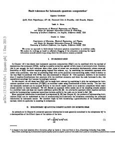
Recent technology advancements and emerging techniques in computing and communication systems have enabled the design of small-size, low-power and low-cost embedded devices. These technological progress provides key technologies for smart systems that encompass computational (i.e., hardware and software) and physical components, which are seamlessly integrated and closely interact with the physical world. These advancements provide a technology basis for manifold areas of innovation. Embedded systems are penetrating ever more into applications where, until recently, computing technologies played no significant role. Examples include medical devices, aerospace systems, transportation vehicles, factory automation, building control and power generation [77, 154]. According to [145] in the fields of manufacturing, transportation, intelligent buildings, health care, emergency response, and defense systems the value share of computational smart devices is expected to exceed 50% of the costs by 2020. A malfunction of systems that sense and control the physical world could lead to serious consequences such as loss of life, significant property or environmental damage, or large financial losses. Consequently, ensuring that the systems work as intended is of utmost importance. However, since the embedded systems have to manage ever more demanding and complex tasks, guaranteeing their correct behavior under any circumstance is more challenging than ever. Even if designers do their best to remove hardware defects and software bugs before the system is released, history shows that such a goal is virtually impossible to achieve [7]. Unfortunately, it is unavoidable that unexpected environmental factors will not be taken into account. Even if the system is designed and implemented perfectly, faults are likely to be caused outside the control of the developers. The challenge of creating a dependable system increases dramatically with the increasing complexity of computing systems. The trend to ever more complex processor-based systems can be demonstrated by the amount of software deployed. Figure 1.1 illustrates the growth of software complexity by looking at military airplanes that have been developed over the last few decades. In the 1980s, a typical military fighter jet contained only about 100,000 Source Lines Of Code (SLOC). With the release of the F-22 Raptor aircraft in 2002, this number increased to approximately 1.7 million. In 2010, a modern fighter jet (Lockheed Martin F-35) required about 5.7 million SLOC. The next-generation of these jets will offer even more advanced features realized with over 8 million SLOC [37, 129, 130,
23
1 Introduction
SLOCs of a Typical Fight Jet 12,000,000
SLOCs
10,000,000 8,000,000 6,000,000 4,000,000 2,000,000 0 1980
1990
2000
2010
2020
Release Year Figure 1.1: SLOCs deployed in typical military jets released in the last decades. The numbers are obtained from [37, 129, 130, 147].
147]. Other popular examples to express the enormous complexity of embedded software can be found in the avionic and automotive industry. For example, the Boing 787 flight software controlling the fly-by-wire system includes about 14 million SLOC [127]. Even a modern car runs about 100 million SLOC [37], and this number is going to grow rapidly with the advent of autonomous driving techniques.
1.1 Dependability: Challenges and Opportunities For the acceptance and use of Cyber-Physical Systems (CPSs) and Internet of Things (IoT) issues of reliability, safety, and security play a key role [145]. Unfortunately, embedded systemsoften have to cope with unforeseen scenarios caused by an increasing number of faults that jeopardize the dependability. The causes of an increased probability of a fault occurring are numerous: • Operational hardware faults occur more and more frequently due to the continuous clock frequency upscaling and structure and voltage downscaling by the semiconductor industry, which leads to highly integrated but also highly sensitive devices. Reliability issues arise from permanent hard errors due to manufacturing, process variations, aging, and wear out effects [86]. Furthermore, there are ever more soft errors caused by energetic radiation particles, capacitive coupling, electromagnetic interference, and other sources of electrical noise [161].
24
1 Introduction • Software faults are on the rise due to the dramatic increase of software complexity [153]. Despite ongoing improvements in software fault prevention techniques, faults remain in every complex embedded system. Unfortunately, testing can only show the presence of faults, but can never show their absence [59]. Thus, it is impossible to fully test and verify that a system is fault free. The urgent need to cope with software bugs can be illustrated by looking at a modern car containing about 100 million SLOC. Considering that a typical well-tested software includes about 2-3 bugs per 1000 SLOC as stated in [182], it can be assumed that about 200,000 software bugs remain in vehicles used every day. • Security attacks causing malicious faults pose an emerging risk, since the extended interconnection and physical accessibility of embedded systems significantly increases their vulnerability to attackers injecting malicious faults into the system. However, the high density of integration not only causes ever more faults to arise, but also provides opportunities to establish mechanisms to tolerate these faults. The shrinking feature sizes of semiconductors facilitates the creation of powerful and low-cost hardware systems. This provides capabilities to establish cost-efficient redundancy. For example, the trend to multi-core processors in the embedded domain allows the additional resources available to be taken advantage of in order to establish redundancy at a relatively low cost [136, 142]. For example, multiple cores computing the same calculation can realize spatial redundancy. Another option is to establish temporal redundancy by exploiting the idle times of a core to perform the same operation multiple times.
1.2 Trend to Off-the-Shelf Processors To manage the ever increasing complexity in various application domains, engineers have changed their way of creating processor-based controllers. For example, for nearly a century various types of specialized mechanical and electromechanical devices performed different well-defined tasks in hydropower plants. Today, renewable energy sources like wind or solar are integrated into the power grid on a grand scale, which causes challenges concerning the predictability of energy conversion [128]. To achieve overall grid stability, advanced computing technology is needed. Thus, future generations of hydroelectrical power plant controllers are strongly interconnected and based on a common advanced hard- and software platform [5]. This platform is not equipped with a specially-designed processor, but is based on a common Commercial Off-The-Shelf (COTS) hardware platform that is intended for communication- and multimedia applications. Similar trends can be observed in other domains, such as the avionics and automotive industry [25, 147]. In the 1980s, military avionic systems implemented each function using a dedicated processor. However, this high amount of separate processor-based systems has significant drawbacks on size, weight and power. Consequently, today many different
25
1 Introduction functions are realized in software which is executed on a common hardware platform. The same trend can be observed in the automotive domain, where designers are facing the challenge of creating communication networks for more than 100 Electronic Control Units (ECUs) [149]. To lower the amount of data that has to be transmitted, the developers aim to integrate the functionalities of multiple ECUs into one more powerful device [142]. At the same time, not only is the number of features that embedded systems have to realize getting ever higher, but many of these features are getting ever more performanceintense. This is due to the advanced tasks they perform. For example, computer vision functionalities required for autonomously driving cars have to execute complex computations in a short time, which results in high performance demands. Another big issue for the commercial value of CPS and IoT applications is to reduce the costs required to develop and produce the computing systems. The authors of [81] claim that “developers of traditional critical applications have seen their budgets shrinking constantly, to the point that COTS, which are not specifically designed, manufactured, and validated, are nowadays mandatory to cut costs”. To sum it up, embedded systems have to satisfy ever-growing demands for high computing performance, number of implemented features and cost efficiency. To ease the development of applications with high dependability requirements, there are safety-certified processors available that guarantee a safe operation with a certain probability. They offer advanced fault tolerance features such as opaque redundancy (lockstep processors), onchip error correcting codes, or radiation-hardening techniques. However, as illustrated in Figure 1.2 they offer only a limited performance compared to COTS multi-purpose processors. As far as the author of this thesis knows, today the most powerful safety-certified processor platform is the Infineon AURIX TC29xT series offering three TriCores operating at maximum frequency 300 MHz, where only two processors can be exploited by the software programmer1 [99]. For many advanced application scenarios this hardware performance is not sufficient. This and economic reasons lead to a move to COTS hardware components. According to a NIST study [145] the key challenges of CPS development include what is needed to cost-effectively and rapidly build in and assure the safety, reliability, availability, security and performance of next-generation cyber-physical systems. An additional key aspect is the assurance that the systems become fault tolerant and adaptive. Although many COTS hardware platforms provide a high level of performance, they typically only sparsely offer hardware-based fault tolerance features. Hence, the software has to supervise the correct behavior of the underlying hardware. Consequently, the software becomes the most critical part of the system. Thus, the software itself must be correct (i.e., correctly implement the specifications). Moreover, the software should be effective in coping with errors affecting the underlying hardware. 1
The third core is realized as a redundant lockstep processor.
26
1 Introduction 65 Safety-certified Processors
60
Intel Atom C2358
COTS Processors
Price [USD]
50
Intel Atom D2550
Freescale Qorivva MPC5675K (e200z7) Infineon AURIX TC297T*
40
Allwinner Tech SoC A20 (ARM Cortex-A7) NXP i.MX6D (ARM Cortex-A9)
TI Hercules TMS570 Infineon AURIX TC275T* Freescale Qorivva MPC5675K (e200z7) Renesas RH850
30
20
10
NXP i.MX6DL (ARM Cortex-A9)
NXP i.MX 6SoloX
ARTIK 1 (MIPS)* NXP LPC4330 (Cortex-M4/M0) TI Dual Core Delfino TMS320F2837xD
0
0
0.2
0.4
0.6
0.8
1 1.2 Core Frequency [GHz]
1.4
1.6
1.8
2
*prices obtained from phonecalls with the manufacturer
Figure 1.2: Comparison of various 32-bit dual-core safety-certified and COTS processors regarding price and core frequency. The prices correspond to the price when buying one single piece shown on the reseller website www.mouser.de and ark.intel.com on 2016-03-11. The prices of the processors labeled with “*” are obtained from personal phonecalls with the manufacturers on 2016-03-14.
1.3 Problem Statement In this doctoral thesis, we aim to increase the fault tolerance of embedded systems. However, most of the principles and techniques described herein are generally applicable and could also be used for other types of computer-based systems. We mainly focus on handling hardware faults. However, the mitigation of software and malicious faults is also considered. When developing software-based fault tolerance for COTS-based embedded systems the main challenges are • the assessment of software-based fault tolerance mechanisms, and • the design of these mechanisms, including – techniques for fault detection during operation, and – means to adapt the system to achieve fault recovery.
27
1 Introduction
1.3.1 Assessment of Software-Based Fault Tolerance Without Detailed Hardware Models When developing fault-tolerant COTS-based systems, a key challenge is to obtain an understanding of how specific hardware faults affect the software execution. The goal of Fault Injection (FI) techniques is to understand and assess these effects. Thus, FI is essential for researchers and developers investigating special software techniques to detect and tolerate hardware faults. A famous example of software that is especially designed to offer fault tolerance is Software-Based Self-Tests (SBSTs). They offer self-diagnosis features to detect operational hardware faults in the field. To assess the quality of such self-tests, safety standards such as the IEC 61508 [100] or ISO 26262 [102] require the evaluation of their fault diagnostic coverage via FI experiments. Other examples of software ensuring the correct functionality of the system include software countermeasures for mitigating malicious fault attacks. To identify potential weaknesses of a system regarding such attacks and develop appropriate countermeasures, FI is needed. However, FI is not only needed to assess specific fault tolerance software, but also to evaluate the robustness of functional software. Analysis techniques, such as softwarebased FI, are required to understand the impact of hardware faults on the behavior of the software and the whole system. In order to prevent late-stage redesigns due to reliability targets that are not fulfilled, it is preferable to evaluate the vulnerability of functional software to hardware faults throughout various development stages. Since the reliability of critical processor-based systems has been of concern for many years, a wide range of publications exist regarding test methods using FI techniques. Many proposed FI campaigns target completely manufactured parts (e.g., using radiation or manipulation) [20]. However, such techniques can only be applied during very late development stages. Therefore researchers created various simulation-based and emulation-based FI tools. Most of the proposed FI techniques require a model that describes the detailed design of the processor (e.g., hardware layout, Register Transfer Level (RTL) model, or netlist) [117]. However, this information is typically not available when using third-party COTS processors. Other FI techniques require a modification of the source code. Consequently, they are not applicable if the source code is available. However, there is the trend to accelerate the software development of embedded systems by buying and integrating closed-source COTS software parts from third-party companies. Thus, there still exists a major need for an FI tool that is applicable in early development stages. The tool should provide an understanding and measurement of how hard and soft errors affect the behavior of the software. To ensure a high level of feasibility, a simple integration into existing tool chains is desired. Moreover, the FI tool should be applicable without knowing hardware or software implementation details needed to support the usage of COTS hardware and software components. Although, researchers have proposed tools
28
1 Introduction that support such COTS components, these tools often have major limitations such as relying on specific hardware components, or limited fault modeling capabilities. Hence, one goal of this thesis is the development of an FI tool that allows software developers and researchers to investigate the effects of hardware faults on the software execution without changing the source code and without requiring detailed hardware models. This should support the research on fault tolerance techniques and allow developers to evaluate the robustness of their software.
1.3.2 Limited Fault Detection Capabilities of Homogeneous Redundancy Most faults lead to the consequence that the faulty unit stops or enters an infinite loop and no bad output is produced. Such fail-stop faults can be detected relatively easily by typical fault tolerance techniques, such as a watchdog. However, there are also Silent Data Corruptions (SDCs), where the system continues to run but produces incorrect outputs. Theses faults can be very dangerous since they are hard to detect. An established concept used to handle operational faults is redundancy [89]. Homogeneous redundancy is widely used to detect and tolerate hardware faults. In accordance with homogeneous redundancy, several replicas of the same piece of software are executed redundantly and forward their outputs to a voter. This voter can detect a fault if the outputs of the replicas differ. While spatial redundancy means that the calculation is performed on distinct hardware components, temporal redundancy indicates that the same calculation is subsequently performed multiple times. However, a simple addition of homogeneous redundancy is still vulnerable to CommonCause Faults (CCFs). If all redundant calculations are affected by the same fault, they fail in the same way and the fault is not detected. For example, if two cores of a multi-core system are used as redundant channels, both calculations could be affected by a fault in a shared resource such as the RAM. Furthermore, special attention should be paid to common hardware faults when time redundancy is applied in only one hardware channel: if there is a permanent fault in a processor that is used to subsequently execute the same software binary multiple times, the fault is not detected since it influences all software executions in the same way. Another famous example of CCFs is software bugs. Establishing software fault tolerance presents some unique challenges, since software faults (e.g., bugs in the source code) exist in every instance of the software. CCFs can only be detected if diversity is introduced. The goal of diversity methods is to increase the probability that the consequences of a fault in the diverse variants are different, so that it can be detected [153]. A classic approach to add diversity is N-version programming meaning that several development teams work independently to design and implement N software versions. However, this approach is very cost-intensive. Thus, this thesis aims to identify and evaluate techniques to increase the fault detection capabilities of redundancy-based mechanisms with low development effort.
29
1 Introduction
1.3.3 Recover From Detected Permanent Faults Through Software Adaptation CPS should fulfill high reliability and availability requirements to ensure customer satisfaction. For example, shutting down a power plant due to a fault in the digital control system could cause dramatic economic losses. However, typically the operational life of CPS applications spans many years (i.e., digital systems in power plants, vehicles, industrial production). Thus, there is the need to maintain the availability of the system even in the presence of permanent faults. Even when sophisticated techniques to detect faults are in place, there remains the need for mechanisms to appropriately react to the detected fault. A typical approach to handle a detected permanent hardware fault is to shift the calculation to a spare redundant standby system [125]. However, in many applications there are only a few spare systems available in order to avoid additional costs. Consequently, the means of such traditional fail-over concepts are limited. Thus, in order to increase the availability, it is desired to recover from an identified permanent hardware fault without requiring extensive redundancy. In order to deal with unforeseen events the idea of software self-adaptability has received attention [31]. For example, self-healing systems autonomously detect and recover from faulty states by changing their configuration. However, so far these techniques are mainly used in complex server systems. Methods for embedded systems to recover from an unhealthy state due to a permanent hardware fault are still a research challenge. Many approaches proposed in literature are based on hardware-specific features, which are limited when using COTS hardware. In order to create a software-based recovery of permanent hardware faults, the following question has to be addressed: how can the software execution be changed in such a way that it tolerates underlying permanent hardware faults while maintaining the original functionality? One goal of this thesis is to identify means for such a software-based selfadaptation.
1.4 Contributions The scientific contributions of this thesis are summarized in Table 1.1. Figure 1.3 illustrates the suggested approach for increasing the dependability of systems without causing much development overhead. First, we propose to efficiently exploit inherent hardware fault masking capabilities at software and application level supplementary to established software-based fault tolerance mechanisms. Furthermore, we investigate methods to increase the fault detection capabilities of redundant systems and to recover from detected faults during runtime. To achieve these objectives, appropriate development methods are required. In this work, we suggest reliability-aware development using FI techniques and automated diversity as such methods.
30
1 Introduction
Development Methods
Fault Tolerance Mechanisms in the Product
Reliability-Aware Development
Automated Software Diversity
Model-Checking-Based Fault Injection (FAnToM Tool)
Static Automated Diversity
Simulation-Based Fault Injection (FIES Tool)
Dynamic Automated Diversity
Fault Tolerance Mechanisms
High Inherent Hardware Fault Tolerance
RedundancyBased Fault Detection
Evaluation of
Recovery of Permanent Hardware Faults
Means of design
Figure 1.3: Overview of the contributions of this theses that include techniques and tools that are applied during development to enhance the fault tolerance of a processor-based system during runtime.
1.4.1 QEMU-Based Fault Injection Framework To overcome the limitations of traditional FI techniques regarding COTS-based systems described above, there are proposals to adapt emulators performing hardware virtualization to simulate faults at system-level. The Quick EMUlator (QEMU) [18] is open source and targets the emulation of hardware for embedded systems. It features the fast emulation of several CPU architectures (e.g., ARM, x86, Sparc, Alpha) on several host platforms (e.g., ARM, x86, PowerPC). We propose a QEMU-based Fault Injection framework for the Evaluation of Softwarebased fault tolerance (FIES) that supports an enhanced fault model compared to existing comparable approaches. The framework allows the simulation of faults in the instruction and address decoder, CPU registers and RAM memory cells. The accuracy of the memory cell fault models is increased by taking particularities of memory components into account. Based on the hardware abstraction of QEMU, FIES supports the simulation of widelyused COTS processors, since it only requires knowledge of the instruction set and the basic memory architecture. Furthermore, it also allows the assessment of closed-source Off-The-Shelf (OTS) software, since it simulates a binary execution without the need for adapting the source code or the executable. We have demonstrated that FIES is well suited to evaluate software-based fault tolerance mechanisms. It fulfills IEC 61508 Safety Integrity Level (SIL) 3 requirements regarding
31
1 Introduction fault modeling to assess built-in processor and RAM self-tests. Furthermore, we have also illustrated that the tool is also valuable to the security community to model fault attack scenarios and design appropriate software-based countermeasures.
1.4.2 Reliability-Aware Development to Increase Inherent Fault Tolerance During software development, the impact of underlying hardware faults is typically neglected. However, the vulnerability to hardware faults can significantly be reduced by exploiting inherent fault masking properties and increasing the fault tolerance or to identify bottlenecks and weak points in the design (e.g., where one fault can crash the system) In order to cost-efficiently increase the hardware fault tolerance, we propose to integrate reliability-awareness in different phases of software development. The aim is to close fault tolerance issues as early as possible before physical hardware testing is performed. This poses the need for FI frameworks that are applicable in various development stages. We propose to integrate FI when performing model checking in very early design stages. This supports the design of algorithms in such a way that high-level fault masking properties are enhanced. Additionally, we propose to integrate the FIES framework in various software design, implementation and test stages. The framework provides an easy integration into existing frameworks. Software programmers and test engineers can apply it to assess the impact of hardware faults on the behavior of software at different levels (e.g., individual functions/modules, completely integrated software system).
1.4.3 Automatic Introduction of Software-Diversity in Redundant Systems Since a simple addition of homogeneous redundancy is still vulnerable to faults affecting all redundant channels, we propose to automatically introduce diversity in execution to detect CCFs. Diversity in execution can denote diverse timings, or diverse usage of hardware resources (e.g., diverse processor instructions, or diverse memory locations). We first identified two patterns commonly used in the realization of automated diversity. The first one is static randomization that creates multiple executables derived from a common source code. Then, these variants are distributed. The second one is dynamic randomization that creates only one single version of an executable program, where the diversity of execution can be configured during runtime. Most of these techniques emerge from the security domain. However, we propose to use them in redundant systems for identifying hard-to-detect SDCs. We illustrate the potential of dynamic diversity methods to enhance the fault detection capabilities of redundant systems with small examples. Furthermore, we evaluate the potential of diverse compiling - a simple static diversity technique - in more detail. Diverse compiling exploits the diversity introduced by different compilers and different optimization flags. However, so far no significant statistics regarding the efficiency of the approach for detecting certain types of faults have been published.
32
1 Introduction We have evaluated the diverse compiling approach regarding its ability to detect faults in the microprocessor. Our fault injection campaigns show that for exemplary benchmarks about 90% register faults and 70% instruction decoder faults can be detected. Furthermore, we have shown that this approach even enhances the software fault tolerance by increasing the chance of finding defects in the source code of the executed software during runtime. More precisely, it enhances the chance of detecting memory-related software bugs, such as missing memory initialization, during runtime. We experimentally quantified the efficiency of diverse compiling for software fault tolerance and we have shown that diverse compiling can help to detect up to about 70% of memory-related software bugs. Adaptive software diversity There is a lack of methods that allow embedded systems to recover from detected faulty states. In order to contribute towards filling this gap, we introduced the high-level concept of adaptive dynamic software diversity. The main idea is to create a feedback-based system that adapts the execution of the program in such a way that a fault is bypassed regardless of its root cause. One way to achieve this is to adapt the execution with dynamic diversity techniques. Furthermore, we also proposed to bypass detected permanent faults by updating to an executable that performs the same functionality but masks the fault. We have demonstrated that diverse compiling can be used to generate such a binary.
1.5 Organization of the Thesis The rest of this dissertation is organized as follows. Chapter 3 discusses existing work in the area of fault injection and automated software diversity as a fault tolerance mechanism. Then, proposed approaches for fault tolerance evaluation with fault injection are presented in Chapter 4. Followed by Chapter 5 describing how to achieve fault detection and fault recovery by using techniques that automatically introduce diversity in software. Finally, Chapter 6 concludes this thesis by summarizing the obtained results beyond the state of the art, and by providing hints on future research directions.
33
1 Introduction Table 1.1: Overview of the contributions of this thesis
Challenge Assessment of software-based fault tolerance
Contribution • FAnToM tool for the early evaluation of inherent fault tolerance of algorithms for redundant systems using a modelchecker (Chapter 4.2, Paper A). • FIES tool for simulating the effects of hardware faults on software based on the emulator QEMU (Section 4.3) and illustrations of applications possibilities during software development: – Enhancement of inherent fault tolerance of software through the integration of FIES in various software development stages to support reliability-aware software-development (Chapter 4.1, Paper C). – Assessment of special fault tolerance techniques including SBSTs (Chapter 4.3.5, Paper B) and fault attack countermeasures (Chapter 4.3.5, Paper D).
Limited fault detection capabilities of homogeneous redundant systems
• Identification of established patterns to automatically introduce “diversity in execution” (Paper E, Chapter 5.1) and application of these techniques for redundant systems (Paper H, Chapter 5.2). • Evaluation of fault detection enhancements when applying diverse compiling regarding – memory-related software bugs (Chapter 5.4.2, Paper F), and – permanent microprocessor faults (Chapter 5.4.3, Paper G)
Recover from detected permanent faults through software adaption
• Adaptive software-diversity to recover from faults (Chapter 5.3, Paper K) using – dynamic automatic diversity techniques, (Paper H), and – static automatic diversity techniques (Paper J).
34
2 Background “Failure is simply an opportunity to begin again, this time more intelligently.” – Henry Ford This chapter provides definitions of key terms and a brief introduction to the theoretical backgrounds related to this thesis.
2.1 Embedded Systems, Cyber Physical Systems and Internet of Things Due to the great impact on society and economy, the topic of integrating connected computing devices into the physical world has generated considerable recent research interest. This resulted in numerous definitions and terms with a close affinity. Embedded systems in the in the traditional sense perform well-defined sense and control tasks using a small microprocessor with limited resources [163]. According to Bar and Massa [13] an embedded system is a combination of computer hardware and software - and perhaps additional parts, either mechanical or electronic - desired to perform a dedicated function. Often embedded systems have to fulfill high reliability and real-time requirements. Consequently, the development focus lies on the hardware/software interface, Real-Time Operating Systems (RTOSs), and code optimization. Sometimes the term embedded system is also related to not only applications with physical aspects, but also to mobile consumer applications, such as smartphones or tablets. Today, the increasing complexity of computing systems interacting with physical processes causes ever higher demands on functionality, robustness, adaptation, and connectivity [163]. To express their difference to traditional embedded systems, Helen Gill at the National Science Foundation introduced the term CPS in 2006 [123]. The three key technologies of CPSs are communication, computing and control. Furthermore, there is the term IoT, which the International Telecommunication Union defines as a global infrastructure for the information society, enabling advanced services by interconnecting (physical and virtual) things based on existing and evolving interoperable information and communication technologies [104].
35
2 Background Throughout this thesis the term embedded system denotes not only the traditional, highly specialized systems, but also processor-based devices that form CPS or IoT infrastructures.
2.2 Dependability and Security Definitions Dependability describes the systems ability to deliver its intended service to its users [119]. As computing becomes ubiquitous and penetrates our everyday lives, dependability becomes ever more important not only for traditional safety-critical applications, but also for our society as a whole [62].
2.2.1 Dependability Attributes Dependability is an integrated concept encompassing the following key attributes: • Reliability: the continuity of correct service. • Availability: the readiness for correct service. • Safety: the absence of catastrophic consequences on the users and environment [9]. Additionally, there are the attributes integrity, denoting the absence of improper system alterations, and maintainability, denoting the ability to perform repairs. Security also considers confidentiality, which means the absence of unauthorized disclosure of information in addition to availability and integrity. While dependability focuses on non-malicious faults, security mainly targets the mitigation of malicious faults. Although malicious faults are partially considered in this thesis, techniques to assure integrity and confidentiality (e.g., cryptographic principles) are out of scope (see Figure 2.1). Availability Reliability Dependability
Safety Confidentiality
Security
Integrity Maintainability
In the scope of this thesis
Figure 2.1: Dependability and security attributes with indication of the focus of this thesis. Adapted from [9].
36
2 Background
2.2.2 Dependability Threats Faults, errors and failures are threats to dependability, which can be distinguished as follows (see Figure 2.2) [9]. If a fault is active it produces an error, which in turn can produce a failure. Otherwise, the fault is dormant. More specifically, a fault describes an incorrect state. If the fault is activated, an error indicates the deviation from the specification that influences the systems’ functionality. If this error leads to the consequence that a desired external service is no longer delivered, it is called a failure. Whether a failure occurs depends on the execution that takes place after the error occurred. Note that faults do not necessarily become errors, and errors do not necessarily become failures. ...
fault
activation
error
propagation
failure
causation
fault
...
Figure 2.2: Fault-error-failure chain. Adapted from [9].
2.2.3 Dependability Means Means to maintain dependability can be grouped into four categories [9]: • Fault prevention: to prevent the occurrence of faults. • Fault tolerance: to avoid failures in the presence of faults. • Fault removal: to reduce the number of faults. • Fault forecasting: to estimate the present number, the future incidence, and the likely consequences of faults. Despite ongoing improvements in fault prevention techniques, faults remain in every complex software system. For example, to ensure the quality of software, exhaustive program testing is strongly recommended. However, program testing can only show the presence of bugs, but never shows their absence [59]. Thus, it is impossible to fully test and verify that a software or hardware is fault-free. In addition, faults might be introduced during operation. To face this problem, fault tolerance mechanisms are required in order to maintain operation even in the presence of faults [50]. In recent years, the term resilience has also gained popularity in the area of information and communication technologies [179]. According to [70] software resilience refers to the robustness of software to adapt itself so as to absorb and tolerate the consequences of failures, attacks or changes within and without the system boundaries. Hence, to make systems resilient, they have to cope with changing circumstances regardless of their root cause [179]. In addition to traditional fault tolerance, resilience also considers the mitigation of threats that are caused by a changing system and environment and are not known at design time.
37
2 Background
2.3 Fault Types Faults can be classified by considering the multiple dimensions of their source of origin, location and persistence as depicted in Figure 2.3 [9]. Basically, there are three major groups of faults, which partially overlap: • development faults including all faults that are introduced during development, • physical faults including all faults that affect hardware, and • interaction faults including all external faults. Faults can be caused by natural phenomena (natural faults) or result from human actions (human-made faults). During development, production defects can cause natural faults. During operation, natural faults are either internal (e.g., caused by physical wear-out effects), or external (e.g., radiation, noisy input lines). Human-made faults are either introduced with malicious objectives or they are caused by human mistakes or bad decisions (e.g., due to economic considerations). Nonmalicious development faults can exist in hardware (e.g., faults in microprocessors) and in software (e.g., coding bugs). The IEC 61508 standard [100] defines permanent and transient faults according to their persistence. In contrast to permanent faults that persist for the remainder of the computation, transient faults occur for a short period of time. Software faults are always permanent, although they might be dormant. However, they exist in every instance of the software. In hardware, permanent faults might be introduced during development (e.g., manufacturing or design faults) or they appear during operation. Permanent operational hardware faults reflect long-term damage of hardware components and cause hard errors. Transient faults are mainly caused by temporary environmental influences such as neutron and alpha particles, power supply and interconnect noise, electromagnetic interference or electrostatic discharge. Such faults cause soft errors. They occur more and more frequently due to the increasing density of hardware components. Additionally, intermittent Faults Development
Phase of creation
Internal
System boundaries Humanmade
Phenomenological cause Dimension Objective Persistence
Operational
SW
HW
Internal
External
Natural
Natural
Natural
HW
HW
HW
Nonmal
Nonmal
Nonmal
Mal
Mal
Nonmal
Nonmal
Per
Per
Per
Per
Per
Per
Tr
Per
Humanmade HW
SW
Nonmal Tr
Per
Nonmal
Mal Tr
Per
Tr
Figure 2.3: The classes of combined faults. Adapted from [9].
38
Per
Mal Tr
Per
Tr
2 Background faults appear repeatedly and periodically at the same location and produce errors in bursts while they occur. Such faults can be triggered by unstable hardware due to process variations and manufacturing residuals. Regardless of the root cause of a fault it might have different impacts on the system [81]: • Effect-less fault: The fault does neither propagate as an error nor as a failure • Failure: The fault propagates within the system until it reaches the system boundary – Failstop faults: The system comes to a stop (e.g., crash, timeout) – Silent Data Corruption (SDC) faults: The system continues running but produces incorrect outputs. SDCs in redundant systems sometimes are also referred as Byzantine faults [118]. These faults are considered to be the most difficult class of failure modes, since a Byzantine fault presents different symptoms to different observers [61].
2.4 Hardware Faults Here, we first describe the causes of hardware faults, then we continue to outline common approaches for modelling hardware faults, and finally provide some statistics about how often they appear.
2.4.1 Origin and Classification of Hardware Faults Faults can be introduced during various stages of hardware development such as specification, implementation, or fabrication [62]. Additionally, they can be caused by external factors, such as environmental disturbances or incorrect human interaction. During operation, physical defects, such as shorts in a circuit, broken interconnection, or stuck cells in memory can cause permanent faults [25]. The reasons for such defects might be internal wear-out effects (e.g., electromigration) or external effects (e.g., radiationinduced burnout). Similarly, also the origin of transient faults may be internal (e.g., crosstalk, coupling effects), or external (e.g., radiation, electromagnetic interference) [161]. A dominant concern in reliability research are radiation-induced faults. While these faults have long been an important issue for space applications, they are nowadays also becoming a significant vulnerability for terrestrial systems [81, 159]. The causes of transient faults are mostly environmental, such as alpha particles, atmospheric neutrons, electrostatic discharge, electrical power drops, or overheating. Reasons for intermittent faults are implementation flaws, ageing, and wear-out, and unexpected operating conditions. For example, a loose solder joint in combination with vibration can cause an intermittent fault.
39
2 Background
2.4.2 Modeling of Hardware Faults Since it is not possible to enumerate all types of faults that can occur, faults are assumed to behave according to a fault model [62]. This makes the evaluation of fault coverage possible. Hardware error models of a processor-based system can be described with a twotier approach: hardware-level and system-level faults [81]. At the bottom there are the hardware components of the processor-based system (e.g., memory modules, Arithmetic Logic Unit (ALU), control unit). At the top there is the information the system handles (i.e., program data, program instructions). Among others, we consider the following hardware-level fault models as described in [81]: • Stuck-at (Stuck-At Fault (SAF)) is defined as a logical, hard and single error resulting from faults in hardware affecting system components. This may result in signals that permanently stuck either at the logical value 0 (SAF-0) or at 1 (SAF-1). • Bit-flip is defined as a logical, soft and single error resulting from hardware faults that change a memory element of the system. A bit-flip inverts the content of a memory cell from a logical 0 to a 1 or vice-versa. Whereas a SAF and single bit-flip denote the occurrence of one of these faults, multiple faults mean that there is more than one fault a time [62]. Hardware-level faults can be mapped to high-level system-level faults. There are two main classes of system-level fault effects [81]: • Data error is defined as a single logical error that alters the program’s data. This definition does not consider the location in the system where the data is actually stored (e.g., main memory, processors cache, or a register file). • Code error is defined as a single logical error affecting the instructions of the program’s code. Such an error might change the control flow of the program.
2.4.3 Frequency of Occurrence Although the actual Failures In Time (FIT) rates of COTS processors are kept secret, researchers speculated on these rates by combining publicly available data from different manufacturers [157]. However, since many different factors can influence the failure rate, such statements should always be treated with caution. For example, researchers showed that different technologies for the manufacturing of the same design can lead to different soft-error rates. Smaller feature sizes enhance the sensitivity to transient faults. Also the reduction of the supply voltage increases the sensitivity to Single-Event Upsets (SEUs) in memory cells [60]. Combinatorial logic is assumed to be less vulnerable than memory cells [21]. This is due to multiple masking effects, such as logic masking, electrical masking and latchwindow masking (fault appears at a different time to the clock edge event). However,
40
2 Background it is expected that the electrical masking effect decreases with shrinking feature sizes, and the latch-window masking worsens with increasing clock frequency. Thus, faults in the combinatorial logic are becoming ever more important for complex processor-based systems. However, there are no meaningful numbers describing the frequency of such faults, which are publicly available [157]. According to [174] the fault rate of Static RAM (SRAM) cells that are mainly used to implement the cache of CPUs varies between 100 and 1000 FIT/Mb. This means that the Mean Time To Failure (MTTF) would range from a little less than 1 year to over 500 years. There appears to be no significant correlation between the fault probability of an SRAM cell and the feature size. However, looking at Dynamic RAMs (DRAMs) the vulnerability to soft errors significantly increases as designs shrink. At the same time the amount of DRAMs in computer systems is expected to increase 50 times compared to 2009 by 2024 [103]. For a long time it has been assumed that transient faults are the dominant concern for various memory cells. However, according to long-term studies from Google [165] and AMD [175], failures are dominated by permanent faults. The reported FIT rates vary between 25,000 and 75,000 faults Mbit per billion hours.
2.5 Software Faults 2.5.1 Origin and Classification of Software Faults Software is not affected by physical constraints such as hardware (e.g., fabrication defects, wear out) [62]. However, software faults contribute to a large fraction of system failures and they are an inherently complex class of faults. The reason for this is that they are introduced by human mistakes. Software always behaves the same way in the same circumstances, unless there are problems in the hardware storing the software. Thus, the main sources of software-related faults are faults in the specification, design and implementation [135]. New faults may be introduced in software due to updates during its life cycle. Due to the complex nature of software development, it is not trivial to identify how software faults originate during the various development phases (i.e., requirement analysis, high-level and low-level design, coding and even testing) [143]. One way to classify software faults is to consider their fault activation reproducibility, which describes the ability to identify and replicate the activation of a fault that caused at least one error. This characterization has important implications on how to design software fault tolerance. Faults that are easily reproducible are called solid faults, otherwise they are called elusive faults. Although software faults are permanent in their nature, they may exhibit a transient behavior and are difficult to diagnose, since it is difficult to reproduce and analyze the events that exposed the fault during test or production. Thus, the author of [82] defined so called Bohrbugs and Heisenbugs. Bohrbugs refer to solid bugs in analogy
41
2 Background to the Bohr atom model. This class of software bugs is relatively easy to diagnose once detected [85]. In analogy to the uncertainty principle of Heisenberg, Heisenbugs refer to elusive faults - they go away when you look at them. This means that they do not manifest themselves during debugging due to the influence of the debugger (e.g., unused memory initialization, timing of events). Heisenbugs are included in the more general class of Mandelbugs. Whereas Heisenbugs are bugs that change their behavior during debugging, Mandelbugs refer to all bugs whose activation condition is related to complex interaction with the system state as a whole (including timing, hardware, operating system, libraries, etc.) [83]. Thus, failures caused by Mandelbugs appear to be non-deterministic, because the same set of input data sometimes leads to a failure and sometimes not. Modeling of Software Faults One popular attempt to model and classify software faults is the Orthogonal Defect Classification (ODC) defining a set of defect types based on the fix made by the programmer to remove the bug [42]. According to data collected from deployed software, the majority of bugs belong to this relatively small set of fault types and are independent from the particular system [144]. One of the benefits of this classification scheme is that it allows the association of the defect types with the activities in different development stages. For example, if there are many function defects, this can be an indication that the development process should be improved in the high-level design phase.
2.5.2 Frequency of Occurrence Today, software faults are the main reason for computer failures [63]. A NASA study evaluated 520 faults that have been identified in mission-critical software. Of these, 61% were classified as Bohrbugs and 39% as Mandelbugs [83]. On the one hand this study highlights that even in mission-critical and well-tested software, there are still many Bohrbugs present, which indicates a significant need for better fault prevention techniques (i.e., test and verification). On the other hand, it also emphasizes the importance of Mandelbugs. More recent studies analyzed the proportion of Mandelbugs in several systems in different domains: a distributed defense system [34], open-source projects (Linux, MySQL, Apache HTTPD, and Apache AXIS) [51], and two enterprise products [41]. These studies led to similar findings to the NASA study. They pointed out that Mandelbugs are especially relevant for embedded systems [41]. In 2006, another study analyzed field data about open source software containing about 650 real software bugs [63]. This study concluded that the set of Orthogonal Defect Classification (ODC) fault types represent a total of 67.6% of all faults that have been collected.
42
2 Background
2.6 Fault Tolerance There are different terms related to fault tolerance [62]: • Fault masking is the process of ensuring that the output is correct even if there is a fault. • Fault detection means determining that a fault has occurred. • Fault location denotes the process of identifying where a fault has occurred. • Fault recovery describes the isolation of a fault to prevent its propagation. Thus, a system recovers by reconfiguring itself such that the faulty component is isolated.
2.6.1 Redundancy Concepts Common to all fault-tolerance approaches is that they introduce a certain amount of redundancy [62]. In general, there are three types of redundancy: spatial redundancy (also called hardware redundancy), temporal redundancy (also called time redundancy) and information redundancy [81]. Techniques presented in this thesis can be applied in temporal and spatial redundant systems. Spatial redundancy means to physically replicate hardware components such as memories, buses, or CPUs [62, 81]. Common ways to implement CPU redundancy are to use redundant processors, or to exploit multiple cores on a multi-core system. For example, lockstep processors execute equal operations in parallel on each core and compare the results in hardware. From the software developers’ point of view, these processors act like single-core processors. Another option is to use multiple cores of a COTS multi-core processor to execute the same software and to compare the results in software. Since spatial redundancy has a significant impact on the size, weight, power consumption, and cost of a system, for some applications it is preferred to spend extra calculation time instead of use extra hardware. Temporal redundancy techniques use only one hardware channel and perform the same execution multiple times subsequently [62]. If a transient error appeared on one of the calculations, the stored results differ. Information redundancy adds coded redundant information to a data item for error detection and masking. M-out-of-N Redundancy Both, spatial and temporal redundancy configurations can realize M-out-of-N (MooN) redundancy [75]. A voter compares the outputs of N redundant calculations and if M of the replicas agree on a specific value it is regarded to be the correct one, otherwise an alarm is forwarded. In other words, M out of N replicas have to provide the correct functionality in order to maintain the availability. For example, in a 1oo2 system, the
43
2 Background operation is maintained if only one channel provides the correct result, whereas in a 2oo2 system both replicas have to agree upon the same output value. Common-Cause Failures CCFs describe multiple failures resulting from a common root cause (i.e., common-mode fault). They should be considered with special care, since they are often hard to detect. In redundant systems they are of special concern, since dependencies between redundant replicas can cause them to fail simultaneously in the same way. So sources of such CCFs are faults in shared resources, or shared environmental factors. Examples of shared root causes of failures are the same production process, design, hardware, function, interface, environment and shared resources like RAM, timer, interfaces and power supply. Moreover, common design faults can cause redundant hardware copies or software replicas to fail under identical conditions in the same way. In temporal redundant systems, permanent faults are common-cause faults, since they affect all subsequent redundant calculations equally. To detect common-cause faults diversity is needed.
2.6.2 Diversity Concepts Homogeneous redundant copies of hardware, data and programs are quite effective to detect transient physical faults and to fulfill a system recovery. However, to tolerate CCFs, a simple addition of redundancy is not enough - diversity is needed to achieve fault-independence. The goal of diversity methods is to increase the probability that if components fail they fail differently, such that a voter can detect an anomaly [153]. The idea of software diversity has already been proposed in the year 1837 by Charles Babbage [11]. He speculated that a particularly complicated calculation could be done in two or more distinct ways and the result is accepted only if it were the same in all of them. For example, homogeneous redundancy is not able to tolerate CCFs caused by design faults. These faults are introduced by human mistakes or erroneous design tools, and so they are reproduced when redundant copies are made. To tolerate design faults, design diversity is needed. This means that the redundant hardware and software elements are created independently. In [8] design diversity is defined as production of two or more systems aimed at delivering the same service through separate designs and realizations. To tolerate common-cause hardware faults, hardware diversity could be established. For example, heterogeneous processor-based redundancy is effective in tolerating microprocessor design faults [62]. Thus, processors from different vendors implementing diverse architectures can be used to execute the same software. Software design diversity is established to achieve software fault tolerance for applications in highly critical domains. Based on the same specification, several development
44
2 Background teams work independently using different methodologies, algorithms, programming languages and compilers to design and implement diverse versions. The most common techniques to integrate design diversity in the system are N-Version Programming (NVP) and recovery blocks. N-version programming At system-level an application environment controls the parallel execution of multiple diverse software variants [81]. Each replica receives identical inputs, processes these inputs and provides a result. Then, a Decision Mechanism (DM) compares these outputs. Thus, this technique works similarly as N-Modular Redundancy (NMR) approaches that have the intention to tolerate hardware failures. The DM is an extended version of a voting mechanism that compares a set of program state variables (i.e., comparison vector) of each replica at a specified cross-check point. Many industrial applications exploit NVP such as, NASA Space Shuttle [152], Airbus A320/A330/A340 [30] and Boing 777 aircraft control [158], and railway signaling and control systems [88, 113]. Recovery blocks Recovery blocks involve a primary module that normally executes the critical software function [81]. An alternate module is used to recover the functionality only if an acceptance test fails that checks the output for correctness. This approach is similar to standby redundancy, which is indented for hardware fault tolerance.
45
3 Related Work “Creativity is just connecting things.”
– Steve Jobs
Here, we first summarize literature about the assessment of software-based hardwarefault tolerance with FI. Then, we outline related work dealing with the design of fault tolerance mechanisms.
3.1 Fault Injection To analyze the fault tolerance, FI techniques intentionally introduce faults into a system [20]. Researchers have proposed numerous FI approaches that target different abstraction levels: physical FI, software-based FI, fault emulation, model-based FI, etc. Since they operate on different layers, they can be seen as complementary techniques for reliability analysis in different development stages.
3.1.1 Fault Injection Techniques for Model-Level Dependability Analysis Modeling-level FI typically operates on system models without the need for a specific implementation. A model that is available in early development stages is a SystemC model. Researchers demonstrated that these SystemC models can be exploited to perform an early stage dependability analysis (e.g., [19, 55, 140]). Other types of early-available models are those used for formal verification [26]. Formal approaches provide a formal quality proof of an abstract mathematical system model (e.g., with a Finite State Machine (FSM)). Besides assertions and theorem provers, model checking is one of the most common formal techniques. A model checker exhaustively and automatically checks whether a given FSM model meets a given specification. In other words, it determines if a model satisfies a set of specified criteria under all circumstances. One advantage of a model checker is that if the criterion is not fulfilled, a counter-example to support the debugging is generated. However, model checkers still struggle with the combinatorial explosion, which limits their applicability to small models [111]. Although, traditionally, formal verification is used to prove correct behavior, it can be exploited to assess the robustness of a designed model under faulty conditions. Table 3.1 summarizes the related work dealing with model-based FI using a model checker. In 1998
47
3 Related Work this idea was presented for the first time by NASA researchers [164]. They modeled the occurrence of a fault by simply introducing a new state in the FSM model. The authors of [115] and [10] focus on analyzing the robustness of hardware circuits. They change the model checker in order to simulate fault effects. Other authors propose only to extend the algorithm model for representing faults. The advantage of this approach is that the well-tested model checker implementation is left unchanged and the fault modeling is more transparent to the user. For example, the authors of [169] show how to change the model of an integrated circuit to analyze the robustness regarding soft errors in latches. Bozzano et al. show how to model faults with the language of the New Symbolic Model Verifier (NuSMV) [27]. They presented an approach to automatically insert faults (SAF and bit-flips), which can be chosen by a user input, into an existing executable specification. How to inject faults in a formal model of a sender-receiver protocol used in a multi-agent system is shown in [67]. In [92], we describe how to formally verify the security properties of an RTL design with a model checker. In this work, we also mention the idea of modeling faults in order to assess the vulnerability regarding fault attacks. All these previous works that check whether a given specification is still fulfilled in the presence of certain faults have one big disadvantage: the model checker stops, once one violation of the specification is identified. Thus, if it finds one such scenario, it provides the events that lead to this situation in a counter-example and stops the execution. However, typically there are numerous combinations of input values, internal states, and possible faults (e.g., time of fault occurrence, fault location, fault type) that lead to a specification violation. Thus, in order to compare the robustness of different algorithms, it is desirable to know how many violations can occur. Then, it is possible to quantify the robustness of a certain algorithm and to compare different design options. In this work, we point out a way of filling this gap. Table 3.1: Overview of related work dealing with model-based FI using a model checker.
Adaptation of MC Model
Work
Evaluation target
Krautz et al. [115] Baarir et al. [10] Seshia et al. [169]
Reliability of hardware circuits
Scheider et al. [164] Bozzano et al. [27]
Reliability of algorithms
x x
Ezekiel et al. [67] Höller et al. [92]
Reliability of multi-agent protocols Security of hardware circuits
x x
This work
Reliability of redundant algorithms
x
48
x x
Quantifiable
x
x
3 Related Work
3.1.2 Fault Injection for Software-Level Dependability Analysis Basically, FI tools for software-level dependability analysis can be classified into those that simulate faults in the software itself (e.g., [143]) and those that simulate how underlying hardware faults affect the software execution. Here, we focus on the latter. Classification of Approaches Hardware-based Fault Injection Hardware-based FI uses additional hardware to inject faults into a target system [187]. Basically, there are two approaches to hardware-based FI: with and without contact. The first approach means that the fault injector directly contacts the target system. The fault is injected by producing a voltage or current, which is injected into a pin of the target. Examples of such techniques are RIFLE [137], FOCUS [43], and MESSALINE [6]. The other class of hardware-based FI techniques uses a fault injector without having direct physical contact with the target [21]. Most of the techniques use external sources to produce a physical phenomenon, such as heavy ion radiation [114] or electromagnetic interference [141]. This phenomenon then induces a spurious current in the target hardware. Simulation-based Fault Injection To eliminate the need to operate on a real hardware, a model of the hardware design can be used to simulate the faulty hardware. Typically, the hardware model is described at RTL level with Hardware Description Languages (HDLs) such as VHDL. The two main approaches of simulation-based FI are to either modify the original HDL model by extending it with fault modeling (e.g., VERIFY [172]), or to exploit built-in commands of simulators (e.g., MEFISTO-C [71], HEARTLESS [160], and GSTF [12]). Emulation-based Fault Injection The main goal of emulation-based FI techniques is to increase the performance of simulation-based FI approaches. To achieve this, the circuit that should be analyzed is implemented on a Field Programmable Gate Array (FPGA) and the development board is connected to a host computer that controls and monitors the FI experiment [116]. Software-based Fault Injection Software-Based FI techniques execute additional software on the target system to modify the system state [187]. This approach allows the simulation of faults in hardware components that are accessible by software. For example, these faults can include register faults, memory faults, dropped or replicated network packets, erroneous error conditions and flags, or wrong timing. There are two main categories of software-based FI techniques:
49
3 Related Work • FI during compile-time: The fault (time, location) is specified before the program is executed. A modified piece of code alters the program to activate the fault, if it is executed on the target system. Examples are FTAPE [178] and FIAT [168]. • FI during run-time: These techniques use a timer to generate an interrupt after a predefined time [21]. Then, the interrupt handler injects the fault. Exception/trap mechanisms use a hardware exception or software trap (e.g., FERRARI [112]) to transfer control to the fault injector. This allows the injection of faults whenever certain events or conditions occur. Code insertion techniques add instructions rather than changing original instructions. A big disadvantage of these approaches is that they are defined for either specific operating systems or application programming interfaces [68]. Furthermore, they only support the injection of faults in hardware components that are represented at the source level. However, hardware faults can occur anywhere in the program, and in any state. So, some of hardware faults that might occur cannot be simulated (e.g., fault in a stack pointer) [184]. Furthermore, instructions or data at high source code levels may correspond to multiple instructions or data at a lower level. OCD-Based Fault Injection Another way to inject faults is to exploit advanced OnChip Debugging (OCD) and performance monitoring features of modern processors (e.g., Xception [33] and GOOFI [1]). One of the major limitations of this approach is the low portability due to the lack of a standard OCD communication interface and different capabilities across processor architectures. Although standard ports (e.g., JTAG) are commonly used to physically interact with OCD features, their capabilities typically vary widely. However, OCD-based approaches do not need any modifications to the running software, allow short simulation times (near real-time) and offer a high level of controllability and observability. Virtualization-based Fault Injection In our work, we propose to adapt a hardware virtualization tool for FI purposes. Some researchers have recently proposed similar approaches, which we call Virtualization-based Fault Injection (VFI). This technique addresses the issues of the above mentioned approaches regarding simulation speed, cost-efficiency, and portability [68]. The idea is to extend instruction set simulators or Dynamic Binary Translations (DBTs) with fault modeling. An instruction set simulator reproduces the execution on a target architecture by executing the target binary code instruction-by-instruction. Contrary, a dynamic binary translator operates on basic blocks in order to achieve a faster simulation [64]. Such an emulator translates all the instructions that are included in a basic block and caches the translated block to accelerate the future execution. Recently, several authors proposed the use of such techniques for fault simulation. Since the FI tool proposed in this work
50
3 Related Work also belongs to this FI category, a more detailed description of the related VFI techniques is presented below. Comparison and Limitations of Fault Injection Techniques Table 3.2 summarizes the properties of different FI techniques according to the criteria described below. Applicability for COTS hard- and software Although it is always necessary to model the hardware in some way in order to simulate hardware faults, there is a big difference in how accurate this model has to be. The trend of using third-party COTS processors highly limits the applicability of FI techniques that are based on a detailed hardware model (e.g., netlist, RTL model). Since this information is highly sensitive intellectual property of the hardware provider, typically such models are not available for embedded system designers. Thus, when using such processors a requirement on the FI tool is that the information that can be found in publicly available documents (e.g., datasheets) is sufficient to model the target hardware. Furthermore, there is also the trend of not only using third-party COTS hardware, but also third-party COTS software components. Often the source code of these software components is not available. In this case, techniques that need to change the software source code are not applicable. Portability regarding target architectures Often the processor used changes from product generation to product generation in order to fulfill new requirements. Therefore, it is desired that FI tools can be ported to other architectures with little effort. When using simulation-based or emulation-based FI this porting is very time-consuming, since a new hardware model has to be developed. This effort is lower for hardware-based Table 3.2: Comparison of fault injection techniques.
FI technique
det. HW model
No need for source code spec. HW setup
Portability HW SW
Hardware-based FI Simulation-based FI Emulation-based FI Software-based FI OCD-based FI
7 7 7 3 3
3 3 3 7 3
7 3 7 3 7
--++ -
+ + + +
VFI (this work)
3
3
3
+
+
51
3 Related Work and OCD-based techniques, since some parts of the framework may be reused for other architectures. However, typically they also exploit many processor-specific features. Thus, adapting such a technique to a new architecture also involves a great effort. Contrary, software-based FI techniques are generally applicable for various hardware architectures, since they are based on a very high-level fault model that does not strongly depend on hardware-specific characteristics. However, traditional software-based approaches are typically designed to evaluate a specific operating system or target application. Thus, the portability regarding changing the target software is very poor. Other approaches are generally applicable for all types of software. Seamless integration in development chain Another requirement of FI approaches is a user-friendly integration in different stages of existing software-development chains. Furthermore, there is no need for specialized hardware which allows a cost-friendly and easier integration with existing tools. We propose to integrate FI into various stages of the software development flow in order to evaluate and increase the fault tolerance of the created work product at different levels (see Paper C). Although, many researchers have focused on FI, only a very few studies show how to apply them during various development stages in domains with high dependability requirements. To the best of our knowledge, only Pintard et al. [148] present an initial approach for automotive development according to ISO 26262. However, their approach depends on techniques that are not applicable when using COTS hard- and software. Public availability There are many FI tools that were never released to the public (e.g., GOOFI [1]), and others are only commercially available for relatively high costs (e.g., Xception [33]). There are very few FI tools that are freely available to the research community. This forces researchers who start working on hardware-fault tolerance techniques, to create their own FI tool for evaluation. Only very recently, parallel to the development of the FI tool presented in this thesis, there have been a few tools released as open source to the public community. In 2014, the authors of [184] provided two open source FI tools. The first one is LLFI, which injects faults in the intermediate code level of the Low Level Virtual Machine (LLVM) compiler. PINFI is the second tool that operates at assembly code level of Intel architectures. Although PINFI is open source it requires the commercially available PIN tool from Intel. Another limitation is that the tools require the software source code and only support a very limited fault model that only includes bit flips of CPU registers. A similar open source tool that also supports permanent memory faults is KULFI [170]. Additionally, in 2015, FAult Injection Leveraged (FAIL*), a versatile and user-friendly FI framework that provides APIs for different underlying hardware emulators (e.g., gem5, bochs), was released to the public [162].
52
3 Related Work Virtualization-Based Fault Injection Tools In 2002, the concept of using hardware virtualization for FI was first proposed by Sieh et al. [171]. They presented the framework UMLinux that exploits virtualization for testing the robustness of networked machines running Linux. A more generic tool that does not depend on the operating system was presented by Potrya et al. [151]. This tool extends FAUmachine with FI supporting transient intermittent and permanent faults in memory cells, disks and network. The goal of FAUmachine is to simulate hardware as close to the corresponding physical hardware as possible, which is the reason for very long simulation times. Another limitation of FAUmachine is that faults cannot be injected into CPU registers and that only i386 and AMD architectures are supported. An approach to unify the API in order to ease the switching to other underlying simulators is FAIL* presented in [162]. This open-source platform aims to increase the reuse of experiment code when changing the target architecture. Today, the simulators Bochs (for x86 targets) and Gem5 (for ARM targets) as well as the OpenOCD debugging interface are supported. The authors plan to extend the tool to also support Quick EMUlator (QEMU) as a back-end simulator in future work. QEMU [18] targets the emulation of hardware for embedded systems. It features the fast emulation of several CPU architectures (e.g., ARM, x86, Sparc, Alpha) on several host platforms (e.g., ARM, x86, PowerPC) with DBT. It implements various optimizations to keep the execution speed of the emulation close to the native execution. Furthermore, QEMU is open-source and offers good portability. The authors of [44] show how to collect program execution statistics with QEMU to improve the efficiency of software-based FI. The approach is to dump the emulated processor state to a statistical module before a target instruction is translated. However, the approach only collects execution statistics, but does not support FI. The authors of [17] use QEMU to inject software faults. They target the evaluation of software fault tolerance with binary mutation-based testing that is performed during runtime. The advantage of this approach is that mutation testing relies neither on source code nor on a certain compiler. Furthermore, the approach is able to inject high-level language faults related to compiler and linker. Another high-level approach targeting software faults is VarEMU, an emulation testbed built on top of QEMU [180]. In 2007, QInject was presented as the first QEMU-based FI environment that supports the simulation of hardware faults [56]. QInject extends QEMU to test the behavior of self-healing operating systems in the presence of faults. It uses the debugging interface of QEMU to inject faults with the GNU Debugger (GDB) into a target back end. The advantage of this work is that an FI experiment could be controlled by a remote GDB session through the network. However, the interface of the debugger and the target backend heavily limits the access to the state of the target system. Thus, the injection of faults in locations that is not accessible is not possible. Furthermore, the approach only takes
53
3 Related Work transient bit flips in General Purpose Registers (GPRs) into account. In 2012, the authors of [45] presented QEMU Fault Injector (QEFI). This tool is an extension of QEMU that allows faults to be triggered with a user defined probability inside CPU, RAM and peripherals. The tool was developed with the purpose of evaluating the susceptibility of operating systems to soft errors. In the same year, the authors of [186] implemented a QEMU-based FI framework to test build-in-test software of avionics systems. They describe functional faults of the memory and define corresponding fault models that are supported by the FI tool. Furthermore, the tool uses an eXtensible Markup Language (XML) file that defines the duration, location and type of faults, as a fault library. However, the work only covers memory faults and not register faults or faults in CPU functional units. In 2013, the authors of [126] presented BitVaSim that aims to test build-in-test software for PowerPC and ARM systems. They use a XML-based fault library similar to the one proposed in [186]. In contrast to the previous works, BitVaSim also supports the interactive definition and injection of faults during runtime. In the year 2014, Geissler et al. [78] also presented a QEMU-based soft error injection methodology. However, their approach only considers bit flips. In [58], Ferraretto et al. use QEMU-based FI to compare the accuracy of instructionlevel FI and RTL-level FI. They show that when simulating faults at registers, the simulated effect when using QEMU or an RTL simulator differs only in 3% of the tested experiments. However, using QEMU for FI is faster and more user-friendly compared to RTL-level FI. In 2015, they extended and improved their QEMU-based FI to provide a faster simulation and to also support Instruction Register (IR) faults as described in [69] and [68]. This tool and FIES, which is part of this work, were developed concurrently, and currently they share many similar features. However, when we started working on this topic, there was no information about the related tool available. Furthermore, until now, the framework of Ferraretto et al. was not released to the public. Table 3.3 and Table 3.4 summarize the differences between QEMU-based VFI approaches that have been published so far. It can be seen that many tools only support the most basic fault modes such as bit flips and SAFs in registers and memory cells. However, in order to achieve a more comprehensive fault tolerance analysis more fault modes are required. For example, the safety standard IEC 61508 prescribes that a system with a high level of criticality (SIL-3) also has to be evaluated regarding the effects of faults in the IR and Address Decoder (AD). We fulfill these requirements by providing the possibility of a more advanced fault modeling (see Paper B). In addition, we also take the physical characteristics of typical RAMs into account by supporting the simulation of memory-coupling faults similar to those described in [186]. Further limitations of related QEMU-based FI tools are that they typically do not support the injection of multiple faults concurrently and to interactively stop the program execution to inject specific faults. In addition, the tools presented in [45] and [68] only support statistical FI. That means that the VFI tool automatically and randomly decides
54
3 Related Work where to inject faults. While this approach might be convenient for performing a statistical reliability analysis, it is limited in terms of controllability and reproducibility. To overcome this limitation the fault library should be defined decoupled from the FI tool itself such as described as best practice in [21]. This also facilitates statistical FI by using scripts that generate random fault libraries. Furthermore, there is the possibility of reusing the fault library when switching to another fault simulator. To sum up, recently there have been various VFI tools proposed that are based on QEMU. We assume that the main reason why there are so many researchers that are concurrently implementing a similar tool is that only Qinject is available as open source [56]. However, this tool offers only a very limited functionality. Thus, different research groups need to create their own FI tool in order to perform research on software-based fault tolerance techniques. The fact that many researchers follow the approach of adapting QEMU indicates that this approach is very promising. In order to foster research on fault tolerance we provide FIES as open source. Table 3.3: Comparison of supported fault models of related VFI techniques based on QEMU. Fault location CPU Memory Reg IR Cell AD Qinject [56] QEFI [45] Xu et el. [186] Geissler et al. [78] BitVaSim [126] Ferraretto et al. [68]
3 3 3 3 3
3 3
3 3 3 3 3
FIES (this work)
3
3
3
Memory-fault mode Bit CoupSAF flip ling
3
3
3 3 3 3 3 3
3 3
3
3
3
Fault duration per.
tra.
int.
3
3 3 3 3
3 3 3 3 3 3
3 3 3 3
3
3
3
3
Table 3.4: Comparison of features of related VFI techniques based on QEMU.
Qinject [56] QEFI [45] Xu et el. [186] Geissler et al. [78] BitVaSim [126] Ferraretto et al. [68] FIES (this work)
Fault trigger PC / time Access 3 3 3 3 3 3
Multiple faults
Not only statistical FI 3
Interactive fault def.
3 3 3
3
3
3
Open source 3
3 3
3
3
55
3
3 Related Work
3.2 Automated Software Diversity We propose to exploit Automated Software Diversity (ASD) techniques that introduce diversity in execution to increase the fault tolerance and resilience of embedded systems. Diversity in execution means that different versions of the same software have different resource usage and timing characteristics while retaining the same functionality. For example, diversity can be introduced by • using different processor registers, • transforming mathematical expressions, • different memory usage, • transforming branch statements, • applying different code-generation options, and • using diverse compilers [153]. Here, we do not attempt to list all techniques to introduce ASD described in literature, but we focus on related work that deals with ASD as such in different application domains. Since this thesis evaluates the potential of the ASD technique diverse compiling in more detail, we finally outline related studies on diverse compiling. The term ASD was formed 20 years ago [15]. Some literature references the same approach as systematic diversity or artificial diversity. Recently, the idea received a lot of attention in the security domain, since it has been proven to be useful to counter attacks by adding uncertainty to the target [91, 121]. The DIVERSIFY1 project founded by the EC FP7 program not only considers increasing the security of a system with diversity, but takes a holistic view of resilience [16]. They explore diversity as a foundation of a novel software design principle aim to tackle the challenge of facing unpredictable changes of requirements, the execution environment or failures (e.g., bugs, attacks). One of their work products is a well-structured and exhaustive survey of the multiple facets of software diversity including ASD [15] published in the year 2015.
3.2.1 Automated Software Diversity for Fault Tolerance In this thesis, we present ideas and approaches for increasing the robustness against both, hardware and software faults. Here, we outline related work in these research domains.
1
http://diversify-project.eu
56
3 Related Work Software Fault Tolerance First, we describe the landscape of established techniques to tolerate software faults. Then, we highlight the potential role of ASD in this landscape. Finally, we present data diversity - the only ASD technique that has been proposed in literature for tolerating software faults. Software Fault Tolerance Landscape To tolerate different software faults types, corresponding fault tolerance techniques are required (see Figure 3.1). Bohrbugs produce the same failure each time the erroneous operation is executed. One way to tolerate Bohrbugs, is to exploit manually introduced diversity. It is unlikely that diverse designs and implementations include the same Bohrbug [143]. Another option is to update the software and deploy a hot fix. Applying such hot fixes for Mandelbugs is much harder, since it is usually difficult to determine the root cause of the failure. A common way to recover from Mandelbugs is to retry the operation that caused an error, since the conditions required to activate the faults tend to disappear due to their transient nature [82, 85, 98]. The most frequently employed approaches to recover from Mandelbugs are to apply a restart, reboot or reconfiguration. Whereas a restart action restarts the software component or service, rebooting means to shut down the whole system (including hardware) and starting it again. Reconfiguration is applied if parameters of the hardware, or the application are changed before performing a restart or a reboot. Although literature mentions that the reason why restarting and rebooting often eliminates the consequences of a Mandelbug is environmental diversity, it is claimed that diversity of the software itself is not required [84, 85]. The authors of [85] justify this claim by referring to the high costs of design diversity. However, we assume that design diversity can be effective at tolerating Mandelbugs, since not only are the chances that diverse software includes the same Bohrbug very low, but it is also very unlikely that they contain the same Mandelbug. Indeed, this approach has the major drawback of excessive costs. One aim of this thesis is to reduce this drawback of diversity by creating it automatically. We show that ASD has the potential to tolerate certain types of Mandelbugs. This way of achieving fault tolerance regarding Mandelbugs has only been briefly sketched in [79]. However, no detailed studies of this approach have yet been published. Additionally, we propose Adaptive Automated Software Diversity (AASD), which adapts deployed ASD techniques to recover from faults. This approach can be classified as a combination of the traditional technique reconfiguration and ASD. Data Diversity Data diversity is the only established ASD technique that is used to establish software fault tolerance [153]. In 1988, data diversity was introduced by Ammann and Knight [4]. The idea is that re-expression algorithms transform the original input to produce new inputs to the redundant variants. After program execution the distortion introduced by the re-expression can be removed in order to obtain the intended output.
57
3 Related Work Software faults Type of Fault Fault Tolerance Mechanisms
Bohrbugs Manual Diversity
Hot fix
Mandelbugs Restart
Reboot
Reconfigure
Hot fix
Diversity Manual Diversity
Automated Diversity focus of this thesis
Figure 3.1: Relationships between software fault types and software fault tolerance mechanisms. Adapted from [85, 177].
Then, a DM compares the resulting outputs. To realize this mechanism N-version programming or retry blocks can be used. Although, the derivation of an appropriate data re-expression depends on the application, it has been shown that it is applicable for a wide range of applications [3]. The goal of data diversity is that a given initial data within the program failure region is re-expressed to an input that exists outside that failure region. Hardware Fault Tolerance In 1990, the capability of diversified program variants to detect hardware faults was mentioned for the first time by Echtle et al. [65]. They presented a virtual duplex system, where the duplicity is achieved by temporal redundancy. Without diversity such a system is able to detect temporal hardware faults. However, in order to also detect permanent hardware faults, which can be regarded as CCFs in a virtual duplex system, diversity is needed. It was reported that by using design diversity the vulnerability to hardware faults can be lowered by about a factor of four. However, they using only design diversity. Lovric also considered the use of ASD for hardware fault tolerance [131]. He proposes using diverse compiling and semi-automatic techniques for randomizing the program source code. Semi-automatic randomiziation techniques require the programmer to decide whether the modification is still semantically correct or not. The authors showed that when using semi-automatic program transformation and design diversity the probability that a hardware fault is not detected can be reduced from an average of 10.87% to 0.14% [132]. Building upon these results Jochim created an enhanced tool to diversify disassembled code [108]. In 2011, coded processing was introduced [138]. This technique increases the hardware fault tolerance similar to data diversity [29]. It involves a coded compiler that generates a diverse software variant by applying a specific data encoding. However, all these approaches have the major disadvantage that they typically result in a significantly higher demand for processing power and memory consumption. Furthermore, they require explicit tools for diversification, which results in a low portability. These limitations are significantly lower when applying the simple idea of diverse compiling
58
3 Related Work as proposed by Gaiswinkler and Gerstinger [74]. The work conducted in this thesis is greatly inspired by this study indicating the high efficiency of using diverse compilers and compiling options for hardware fault detection. More details about related publications dealing with diverse compiling are presented in Section 3.3.1.
3.2.2 Automated Software Diversity for Security In the security domain, attackers and defenders are involved in a continuous game of cat and mouse. As new attacks appear, new defenses are created in response. If an attacker finds a vulnerability in a software program, he can exploit that knowledge to target all running copies of that program. In [76] the security dangers caused by the software monocultures are illustrated by the dominance of Microsoft products. Almost all security attacks exploit errors that are introduced by humans. Often they are due to programming languages that have neither a strong type system nor an automatic memory management, but offer high performance solutions [121]. Already in the year 1993, Cohen presented several diversification techniques for creating security by obscurity [48]. He stated that the ultimate defense is to drive the complexity of the ultimate attack up so high that the cost of attack is too high to be worth performing. In the last two years, ASD as a way of realizing a moving-target defense against malicious attacks has again gained attention in the security community. ASD can decrease the software homogeneity and increase the cost to attackers by randomization implementation aspects of programs. For example, a software program could be randomized each time it is deployed on a target. The goal is to force the attacker to redesign the attack each time it is applied. As a result, the risk of widely replicated attacks is reduced. For example, to circumvent buffer overflow attacks, used memory locations can be diversified. This forces the attacker to rewrite the attack code for each new target. Diversity has the potential to significantly improve the security with little impact on runtime performance [120]. In [47], the challenge of establishing security on energy CPS systems (i.e., Supervisory Control and Data Acquisition (SCADA) systems) based on COTS hardware and software is highlighted. As a possible solution, the authors present the basic idea of increasing the security of the system by deploying diversified binaries of vendor-provided applications on devices deployed at consumer households (e.g., set-top boxes, smart meters). Since 2014, Per Larsen and his colleagues from the University of California pushed research in this direction by systematically studying the state-of-the art in ASD [120, 121, 122]. Moreover, they proposed diversification techniques for large-scale ASD targeting server-client systems, browser, and mobile devices [28, 53, 95]. In 2015, Hosseinzadeh et al. discussed the possibility of also applying diversification for the IoT [97]. Furthermore, they presented their work-in progress and future work aiming at increasing the security of IoT systems by applying diversification and obfuscation of APIs and operating systems.
59
3 Related Work Recently, researchers have proposed several diversification techniques to increase the security. Examples include binary rewriting [181], instruction location randomization [90], or function outlining [122]. However, the only technique that is actually deployed in real systems is Address Space Layout Randomization (ASLR) that randomizes base addresses when executing applications [80].
3.3 Automated Software Diversity for Self-Adaptive Software Self-adaptive systems that are able to modify their behavior and structure in order to react to changes in the environment or the system itself have become an important research topic [31, 124]. To make systems resilient, they have to cope with changing circumstances regardless of their root cause. For example, self-healing systems autonomously detect and recover from faulty states by changing their configuration. However, so far these techniques are mainly used in complex server systems. Methods for embedded systems to recover from an unhealthy state are still a research challenge. Although hardware faults can be bypassed with self-modifying hardware (e.g., [105, 156]), this technique is not applicable for COTS hardware and only offers limited flexibility. Thus, there remains the need for sophisticated software-based methods to handle unforeseen scenarios caused by faults. According to [124] the design space of self-adaptive systems includes the following dimensions: • Observation: This design decision deals with the question, what information about the external environment and the system itself should be measured and represented internally. • Representation: The system properties and the problem that occurs during runtime have to be represented in order to enable adaption. • Control: Another important aspect of self-adaptability is the decision making that takes place during runtime. Here, the question what parameters should be changed plays a significant role. • Identification: identified.
In order to react to a state of the system, first this state has to be
• Adaption mechanisms: Another very important design decision is the choice of adaption mechanisms. They define how the system can be changed. In this thesis, we focus on adaption mechanisms. We propose the basic concept of leveraging ASD techniques as a means to adapt the behavior of a software system without changing its functionality.
60
3 Related Work In the security domain, self-adaptive systems that aim at dynamically shifting the attack surface, making it more difficult for attackers to violate the security [54]. This approach is called Moving Target Defense (MTD). The authors of [47] propose the idea of using ASD to establish an MTD in energy CPS. They point out that the adaption techniques required to realize the idea are still a big research challenge. In [91] Hole pointed out the high potential of creating anti-fragility by combining software diversity and malware detection to prevent malware becoming widespread. At the same time as we were conducting our research in this area, researchers of the DIVERSIFY project [16] independently presented similar ideas. In [39], they propose to randomly deploy different versions of the same application in additional virtual machines. They propose the use of
[email protected] paradigm as presented in [24] to reason about the system during runtime. In [38] they evaluated the correlation between robustness and diversity of cloud-based architectures. They introduced diversity at system-level in service-oriented cloud-based applications by selecting alternative service providers. These providers implemented different versions of existing software architectures.
3.3.1 Diverse Compiling Influence of Compilers on System Dependability Several studies have demonstrated that the tolerance against random hardware faults depends on the compilation. For example, the authors of [110] and [57] have shown that compiler optimizations affect the architectural vulnerability towards soft errors. Furthermore, approaches to change the compilation process in order to automatically harden the robustness against hardware faults have been presented [36, 139]. However, there remains the need to investigate the effects of compiling on software-fault tolerance. Compiler-based Diversity Techniques Previous research has suggested methods to automatically synthesize diversity in software [15]. Diverse compiling is such a technique. As summarized in Table 3.5 several goals are targeted in the literature about diverse compiling. How compilers can be used to increase the security by introducing diversity has been shown in [185] and [122]. A promising approach is the multicompiler, which introduces randomness in the binary during compilation [96]. The use of diverse compiling for hardware fault tolerance was already proposed in 1994 [133], but no details about the efficiency were given. The authors of [74] present some fault injection experiments showing that it can be used to detect transient and stuck-at register faults. However, they do not use a detailed and realistic fault model and do not mention how many faults they have injected. The goal of this work is to present a detailed study evaluating the effectiveness of diverse compiling to detect processor faults. In contrast to
61
3 Related Work Table 3.5: The goals of diverse compiling research
Approach
Security
Fault Tolerance Hardware faults
Wheeler et al. [185] Larsen et al. [122] Lovric et al. [133] Gaiswinkler et al.[74] DO-178B standard [109] Shing et al. [173]
Software faults Compiler
Executed SW
3 3 3 3 3 3
This work
3
3
[74], more realistic register fault models are applied. Additionally, we examine not only register cell faults, but also register address decoder and instruction decoder faults. The dependability of a compiler is crucial for the safety of a software system, because it directly affects the final executable. Thus, safety standards, such as the DO178B standard [109], state that the development of a compiler should meet the prescribed safety process. However, it also mentions that, the tool qualification process may be adjusted, if multiple compilers are used and the dissimilarity of these compilers can be ensured [183]. This approach has also been used in [173]. In [183] it is mentioned that compiler diversity can help to find bugs in the software during runtime. However, the authors provide no information about which kind of bugs can be detected or how efficient diverse compiling is for software-fault tolerance. This work attempts to contribute towards filling this gap by presenting a quantitative evaluation of the efficiency of diverse compiling regarding software-fault tolerance.
62
4 Fault Injection “Why lifeboats? This ship can’t sink.”
– Bruce Ismay in the movie ’Titanic’
Here, we first describe our proposal of how to integrate FI in the development process in order to achieve a continuous fault tolerance assessment. Then, we describe two FI tools that can be used to achieve this: the Fault Tolerance Analysis Tool using a Model Checker (FAnToM), a model-based FI tool, and the Fault Injection framework for the Evaluation of Software-based fault tolerance (FIES), a VFI tool.
4.1 Fault Injection to Support a Reliability-Aware Development In order to master the challenge of creating software that is effective in coping with faults in the underlying hardware, we propose to create systems that are inherently resilient. This can be achieved efficiently, if the focus lies on those faults that actually have an effect on the application. As illustrated in Figure 4.1 only a few physical faults actually propagate through all layers of abstraction. Thus, we propose to first reduce the number of faults that affect the application at a very high abstraction layer before enhancing the resilience regarding faults on lower levels. During software development, the impact of underlying hardware faults is typically neglected. However, the vulnerability to hardware faults can significantly be reduced by exploiting inherent fault masking properties of software algorithms and by a defensive Physical and Circuit Layer
µArchitectural and Software Layer
Unmasked Faults
Physical faults, which manifest at circuit layer
Application Layer
Unmasked Faults
Assessment at Software-Level (FIES tool)
Unmasked Faults
Assessment at Model-Level (FAnToM tool)
Undetected faults with impact on the application
Figure 4.1: Fault masking at different layers of fault propagation.
63
4 Fault Injection programming approach (e.g., plausibility checks). In order to cost-efficiently increase the hardware fault tolerance, we propose to integrate reliability-awareness in various software development stages. The aim is to close fault tolerance issues as early as possible before physical hardware testing is performed. Thus, in Paper C we propose a continuous faulttolerance assessment analogous to common practices in interactive software development. The idea is to repeatedly quantify the effectiveness of robustness mechanisms and to report this information to the developers. The indication that such an approach is needed is supported by the fact that the authors of [162] have independently proposed a very similar approach at almost the same time. However, a continuous fault tolerance assessment poses the need for FI frameworks that are applicable in various development stages. Here, we exemplify how the FI tools presented in this thesis can be used in various stages of the V-model - a development process that is recommended by many safety standards (see Figure 4.2). For more details about this approach and the description of how it can be applied in a specific industrial use case we refer to Paper C.
Feedback to SW Team
Formal FI
Feedback to HW Team
Feedback to Reliability Engineer
Hardware FI
Software architecture
Integration testing
(Components, subsystems and HW)
Software system design
Integration testing VFI
Module Design
(module)
Module testing VFI
Implementation + Development Tests VFI Verification Output Hardware Fault Tolerance Feedback Fault Tolerance Feedback from Virtual Fault Injection Fault Tolerance Feedback from Fault Injection Integrated into Model Checking
Figure 4.2: Proposed integration of FI during development according to the V-model of the revised IEC 61508-3:2010 standard [101]. Adapted from Paper L.
4.1.1 Fault Injection from Specification to Design The left side of the V-model targets representations of the system before implementation. Here, we propose to integrate FI during model checking in early design stages. More precisely, we propose to exploit the inherent masking properties of algorithms at the
64
4 Fault Injection application-layer. Typically, there are multiple ways to design algorithms leading to the same result. However, different algorithms have different properties regarding the inherent masking of hardware faults. During the development of reliable systems, the question arises, which of the algorithm candidates provides the best option regarding softwarebased hardware fault tolerance. When designing redundant systems, it also has to be decided whether to execute the same algorithm variant redundantly or to combine different algorithm variants to achieve a diverse system. However, there is a lack of tools that allow the comparison of the fault tolerance of different algorithms in early design stages. Therefore, we propose a method based on a model checker that allows the quantification of the robustness of algorithm variants with FI. Section 4.2 describes this approach in more detail. There is also the possibility of applying FIES during these stages, if there is executable software available. For example, if an incremental approach is adapted, an executable version of the software is available earlier.
4.1.2 Fault Injection during Implementation and Test Often, a software system is divided into software modules, which are developed by individual teams. In parallel the hardware development takes place. After testing and integrating the software components, the software system is deployed on the hardware. Typically, FI campaigns are conducted after the integration of hard- and software. If they lead to the result that the fault tolerance of the system does not fulfill the requirements, usually the persons that are responsible for reliability take action. This could involve changes in the hardware or software. For example, additional reliability is established by adding extra fault tolerance methods (e.g., increasing the level of redundancy). To prevent such overhead and late stage redesigns, we propose raising the awareness regarding hardware faults throughout software implementation and test stages. VFI in the Implementation Stage During the implementation stage, the programmer can use the VFI framework to receive reliability metrics for the newly created code. Developers of certain software parts have deep knowledge of their structure and behavior. This can be helpful for improving the fault tolerance characteristics of the software. For example, programmers know the typical value domains of used variables, which helps to create efficient plausibility checks. Furthermore, the code could be modified in such a way that the inherent fault masking capabilities of software are efficiently exploited. VFI in the Module and Integration Testing Stages Hardware fault tolerance assessment using the VFI framework should complement regular functional testing activities to identify less reliable parts of the software. Software test
65
4 Fault Injection engineers know each module and/or the entire software system. In contrast to the implementation stage, the modules and system are regarded more like black-boxes, which can pose new views on the resilience characteristics.
4.1.3 Fault Injection after Integrating Hard- and Software We propose to apply traditional hardware FI after the integration of hard- and software as a supplementary technique to the previously performed FI assessments. For example, the finalized parts can be analyzed regarding their behavior, if there is too high input voltage or if there are disruptive environmental influences (e.g., high temperature). However, it can be assumed that the identified reliability weaknesses will be reduced due to the prior reliability assessments.
4.2 Quantifiable Formal Algorithm Robustness Assessment with Fault Injection using a Model Checker 4.2.1 Approach of the FAnToM Tool We propose a tool called FAnToM for a high-level analysis of the robustness against hardware faults of algorithms. The tool generates fault tolerance statistics that can be used to quantify the fault tolerance of the algorithm variants. These exhaustive fault tolerance statistics can be achieved by obtaining all faults that belong to the given fault model that are not masked by the algorithm. These exhaustive fault tolerance statistics describe all undetected fault combinations. They indicate the input and fault combinations that lead to an error at the output as well as the specific erroneous output value. This information can support designers in choosing from a class of algorithm options for a specific application. The obtained fault statistics are always related to the considered fault model. In Paper A, we showed how to model SAF faults and bit-flips for internal variables and input values. This means that currently we only support data errors. However, the approach could be extended to also support code errors that cause control flow violations. Also the number of faults that are introduced simultaneously has to be considered. In principle the approach is of generic nature allowing the consideration of an arbitrary number of concurrent faults. However, a higher number of concurrent faults that are evaluated leads to significantly more possible states that have to be assessed. The consequence is that the computing power and model checking techniques available today strongly limit this number. In Paper A we exemplify how to apply the approach for two concurrent faults (dual faults) to model algorithms in a redundant system. To demonstrate the working principle of the proposed approach, we showed how to extend the NuSMV model checker [35]. We propose a tool processing the following steps as illustrated in Figure 4.3:
66
4 Fault Injection Model of Algorithm
FAnToM generate
Adapted Model of Algorithm Golden Algorithm Model
Algorithm Model with FI
Specification =?
Exclude already found fault combinations
Model Checker Counterexample
not satisfied satisfied
finished
Figure 4.3: Working principle of the FAnToM tool. Adapted from Paper A.
• Automatic extension of the NuSMV model: The user has to provide a model of the algorithm that should be analyzed. This model is extended by duplicating the given FSM description. The original FSM model is used as a golden reference model. In the duplicated FSM faults are injected. The random occurrence of faults is modeled by describing the activation of faulty behavior as input values. Then, the model checker considers all possible fault combinations, since it tests the correctness of the model for all possible input values. This mechanism is used to test combinations of the following fault properties: – state, when the fault is injected, – fault location (target signal and affected bit), and – fault type (bit-flip, SAF-0, or SAF-1). Furthermore, we add a specification formulated in Computational Tree Logic (CTL) stating that the outputs of the golden FSM and the FSM with fault modeling should match for all possible input values. • Model checking and counter-example analysis: After checking the generated model, the model checker provides a counter-example that includes a scenario of input values and a fault (or fault combination, if multiple faults are modeled) that leads to a violation of the specification. Thus, in an embedded system, this scenario would cause an incorrect output value. Unfortunately, the model checker stops the execution after finding one counter-example. However, in order to identify all
67
4 Fault Injection dangerous configurations, multiple counter-examples are desired. To overcome this limitation, we implemented a Java program that edits the model such that the specification allows configurations that have already been identified. As Figure 4.3 shows, this procedure is repeated until the specification is fulfilled, which means that all unmasked fault configurations have been found. For more details about the implementation of FAnToM, we refer to Paper A.
4.2.2 Example of FAnToM Tool Application for Redundant Systems
Alternative way
stuck-at-1
Do other stuff check
Do some stuff
out = 101
out = 101
Voter
Do final stuff
cond
Do final stuff
out = 101 correct out = 001
check Do other stuff
Algorithm 2
Algorithm 1
In order to increase the efficiency of redundancy strategies we showed in Paper A how the FAnToM tool can be used to automatically evaluate the inherent fault masking properties of different algorithm versions in a redundant Dual Modular Redundancy (DMR) configuration. One of the main decisions when choosing algorithms that should be executed redundantly is whether to execute the same algorithm variant redundantly or to combine different algorithm variants to achieve diverse systems. Although the advantages of a diverse configuration are apparent regarding the higher abilities of detecting software bugs and other CCFs, there is a lack of tools allowing the evaluation of the inherent masking properties regarding operational hardware faults. DMR systems are able to detect single operational faults in one channel, since the second channel produces a correct output. However, it may happen that there is a fault in each of the both channels causing an undetected erroneous output. As illustrated in Figure 4.4, this is the case if the two faults in the redundant channels lead to the consequence that both calculations provide the same wrong output value. The two faults that occur might be similar regarding fault type, and fault location. However, different faults might also lead to the same consequence. The FAnToM tool can be used to identify all such dual-fault combinations.
stuck-at-0
Figure 4.4: A dual fault pair can lead to an undetected error in a DMR system. For example, a SAF-0 fault in the first channel and a SAF-1 fault in the second channel could lead to the same faulty output and thus remains undetected by the voter. Adapted from Paper A.
68
4 Fault Injection Information about all unmasked dual-fault combinations can be used to assess different aspects of the redundant system. In Paper A, we propose some examples of metrics to compare different algorithm options based on this data. For example, the obtained knowledge can be used to evaluate the detection coverage of dual faults, or to get to know to which extent the input workload influences the vulnerability regarding hardware faults. We demonstrated this approach with two simple use cases of algorithms that implement boolean expressions.
4.2.3 Integration of the FAnToM Tool in the Development Flow We propose to integrate the high-level model-based fault tolerance analysis in very early stages of the development flow as shown in Figure 4.5. First, the designed algorithms are represented in a model checking language and the functional behavior as well as safety requirements are formulated in temporal logic, such as CTL. These representations are available, if model checking is applied for functional verification of the high level system design. An example of how to integrate this model checking procedure in the development in a user-friendly way by providing tool support for modeling the algorithm and formulating the formal specification is presented in [32]. After validating the model for functional correctness, the FAnToM tool analyzes the fault tolerance of the modeled algorithms. The designer then has data about high-level hardware faults that are not masked by the algorithm. To increase the expressiveness 1.
Requirements Analysis Requirements
2.
Specification
Algorithm Design
Algorithm design
no
Model checking
FSM algorithm model
Fault tolerance analysis
yes
yes
Further alternatives available? no
Analyse alternatives
CTL Specification
Which is the best design option for the application?
Algorithm verification
Specifications fulfilled?
3.
Formal Verification of Design
Continue to implementation
Proposed Fault-Tolerance at Application Layer
Designer
Input probability density function
FAnToM Tool
Optional FSM model of alternative Fault statistics of all variants algorithm ... Undetected faults statistics of this Variant1 Variant2 Variant n variant
Dangerous outputs
ANALYSIS Best design option
Figure 4.5: Proposed process of integrating the formal fault tolerance analysis in early design stages. Adapted from Paper A.
69
4 Fault Injection of this data, application-specific knowledge can be used to rate the consequences of the unmasked faults. For example, the designer can use an input probability density function denoting the likelihood that the target application will have to process certain input values. This allows the designer to give weights to the detected unmasked fault scenarios. If the unmasked fault appears in a scenario that is very likely it has a higher negative impact on the reliability than a fault scenario that is triggered by a very unlikely workload. Moreover, depending on the application different wrong output values can lead to different consequences. While some wrong output values might be within a tolerance range, others might lead to dangerous consequences. In order to take this into account, the FAnToM tool also provides statistics about the specific resulting wrong output values that are caused by unmasked faults. This allows the designer to pay more attention to those scenarios that lead to more dangerous consequences. After quantifying the hardware fault masking properties of the different given algorithm design options, the designer can take this knowledge into account when choosing a specific option. However, note, that this algorithm property is only one of multiple aspects that have to be considered when assessing algorithms, such as speed, resource requirements, or diversity in redundant systems.
4.2.4 Advantages Compared to Traditional FI A traditional architecture of an FI system includes the following components (see Figure 4.6) [21]. • Target system: Executes the program or functionality, which should be tested while faults are injected. • Fault injector: Injects faults in a target system while it executes commands from the workload generator. • Fault library: Stores the types, durations, locations of faults and the time when the fault should be triggered. • Workload generator: Generates the workload as input for the target system. • Workload library: Stores sample workloads for the target system. • Controller: Controls the FI. • Monitor: Tracks the commands, which are executed and initiates the data collector if necessary. • Data collector: Collects and stores the raw test data. • Data analyzer: Analyzes the data and performs a data pre-processing.
70
4 Fault Injection One of the main challenges when conducting FI experiments is to generate an appropriate workload and fault library. The results gained from an FI campaign are only meaningful if enough FI experiments that cover both, borderline cases and average cases, have been executed. To decide that the number of performed experiments is sufficient is a very hard task. The proposed formal model-based approach allows the automatic generation of the workloads and injected faults. As illustrated in Figure 4.6, when applying the proposed procedure, the model checker automatically performs the tasks of a workload generator, fault injector and monitor of a traditional FI environment. This eliminates the need to generate a workload and a fault library. Workload Generator Workload Lib Controller
Fault Injector Fault Lib
FSM Model (Target System)
Monitor Automatically done by model checker Done by FAnToM tool
Data Collector Data Analyzer
Figure 4.6: Mapping of the FAnToM approach to the components of a traditional FI environment. Since the model checker automatically performs the task of a monitor, workload generator, and fault injector, there is no need to generate a fault library or a workload library.
4.2.5 Scalability Limitations of the Approach Model checkers still struggle with the state space explosion, which limits their applicability to FSM models with a very limited number of states. Basically, a model checker checks all possible scenarios in the sampling space for correctness in a clever way. The sampling space depends on the number and size of input values and the number of possible internal states. Thus, the sampling space grows exponentially with an increasing number of states and input space. Consequently, even if ”only” the correctness of a model in a fault free environment should be shown, only relatively low-complex models are supported by model checkers. Additionally, the number of tested states is significantly increased when also considering different possibilities of fault occurrences. To examine the practicability of the approach, we analyzed several examples with growing complexity using the FAnToM tool. As shown in Figure 4.7 the runtime depends on
71
4 Fault Injection the size of the sampling space and the number of identified undetected fault combinations. We observed that when considering one model, the time to find an undetected fault combination (i.e., one counter-example) stays nearly constant. However, due to the state space explosion, the runtime grows rapidly with the complexity of the algorithm (i.e., the sampling space). For that reason the approach is very limited and can only be applied for very small, but critical parts of the system. Certainly, there is room for improvement regarding the scalability of the approach. Future work could investigate in techniques to reduce the state space in order to increase the size of the evaluable models. Parallelization as proposed in [94] is another possibility to reduce the runtime. However, we assume that is a long way to improve model checking techniques and formal fault analysis to such a level that it is applicable for real-world sized examples. This is the reason why we moved our research focus onto other techniques to increase the fault tolerance of embedded systems.
Figure 4.7: Runtime depending on the number of undetected faults and the sampling space (depending on the size of the input values and the number of internal states). The measurements indicate that the approach is strongly limited by the model complexity [Paper A].
4.3 Virtualization-Based Fault Injection with QEMU To foster research in fault-tolerant software, we made the VFI tool presented herein publicly available1 . Here, we first present our QEMU extentions to achieve FI. Then, we present our fault modeling approach and the proposed FI procedure. Finally, we highlight advantages and disadvantages of the proposed VFI.
4.3.1 QEMU-Based Fault Injection Approach In this section we present FIES that provides FI extensions for QEMU v1.7.0. Although we describe our use-case specific ARM environment, the approach is of a general nature 1
https://github.com/ahoeller/fies
72
4 Fault Injection and can be adopted relatively easily for other architectures. More implementation details are given in Paper B. Fault Injection Components We propose to integrate FI components in the QEMU framework as shown in Figure 4.8. The fault injector reads the current processed ARM instruction and the fault library. This information is then used by the controller to decide, whether and where a fault should be injected. Then, the controller signals the monitor to optionally print information about the injected fault and forwards this information to an analyzer and a collector. Software
Memory/Register Usage Statistics
Target instructions Profiler Monitor Fault Injector
XML fault library
Binary Translation
Intermediate code
Tiny Code Generator
Host instructions
Controller Analyzer Collector
Host operating system (Windows / Linux) Result files Fault Injection Modules
Host platform (i.e. x86)
Application Profiling Modules
Figure 4.8: Structure of the FI framework, its integration in QEMU and the execution environment. Adapted from Paper B and Paper D.
Fault Injector This component orchestrates the FI. It parses the XML fault library and catches encoded ARM instructions. This information is sent to the controller that provides feedback about whether a fault should be injected and the fault location. Based on this information the fault injector introduces different types of faults at different locations using the fault injection mechanism described above. Controller The controller decides on the type of fault that should be injected, the fault location and the duration of the fault. The injected faults can represent permanent, transient and intermittent faults. The definition of transient and intermittent faults includes the duration of the fault. For intermittent faults the period of the fault occurrence is also
73
4 Fault Injection given. Based on this information and the QEMU built-in timer, the controller decides when a fault should be triggered or stopped. The QEMU timer is also used for faults that should be triggered at a specified time. Another supported trigger is based on the current program counter (PC). Therefore, the controller analyzes the PC, which is stored in the virtual register set of QEMU. Additionally, the framework features to trigger a fault, whenever a target memory address is accessed. The monitoring, if a specific memory address is accessed can be achieved with by exploiting the functionality provided by the QEMU-internal soft-MMU. It converts the target-virtual address in a host-virtual address for each memory access. This allows to monitor and change the address and the data of an executed memory operation. Monitor The built-in QEMU monitor supports commands to debug the running system, such as printing the current content of registers. This monitor is extended with commands to inject a defined fault during runtime or to load a fault library. This approach makes it is possible to interactively stop the software execution at any time. The user could then define a specific fault before continuing the execution where the fault has been injected. Data Collector and Analyzer While the data collector redirects the output of the monitor to a file to save logging information for further analysis, the data analyzer provides detailed statistics about the number of injected faults. For specific application goals such as the evaluation of the fault coverage of SBSTs, further statistics (e.g., the number of detected faults) are managed. XML fault library The FIES tool supports a user-friendly definition of faults and an automated simulation of fault injection experiments, a fault library can be defined in XML format similar as proposed in [126]. Exemplary XML parameters are given in Paper B. Profiler Optionally, hardware usage characteristics of the application can be profiled. These statistics then could be used to create a fault library in an efficient way. Therefore, a golden run is executed to record the memory and register usage, similar to that proposed in [44]. QEMU dynamically translates currently processed guest instructions to host instructions. The execution statistics are collected before the translation takes place. More specifically, if the instruction performs a memory or register access, the current PC and the address is logged. Integration of Fault Injection Mechanisms in QEMU To achieve a fast emulation, QEMU performs dynamic translation as illustrated in Figure 4.9 [18]. After decoding a guest instruction, micro-operations are generated. They
74
4 Fault Injection represent a non-target-specific intermediate code, which is assembled for readability. The translated micro-operations are stored in a buffer and translated by the tiny code generator, whenever a branch occurs. Then the translated micro-operations are executed and grouped to translation blocks, which are stored in a translation cache for a fast subsequent use. QEMU supports a soft Memory Management Unit (MMU) that translates the virtual to the physical address at every memory access. A data structure storing the current internal state of the CPU (CPUARMState) is used for execution. This struct holds information about the internal CPU registers, the current Program Counter (PC), status flags, etc. Note, our targeted ARM architecture (ARM9) offers 16 instructions that are directly accessible. The registers r0 to r12 are GPRs. The remaining registers are special function registers: stack pointer (r13 ), link register (r14 ), and PC (r15 ). To simulate transient and intermittent faults, we disable some of the internal caching mechanisms of QEMU. We built-in the following FI mechanisms in the dynamic translation (see Figure 4.9): • Instruction fault: A certain instruction is replaced by another given instruction. This is done during the disassembling of the host instruction. • Register decoder fault: This fault causes an incorrect register (r0-r15 ) to be addressed. This is implemented by changing the target register in the read and store register functions that are used during the translation. • Current Program Status Register (CPSR) cell fault: The CPSR stores the following ARM flags: carry (CF), negative or less than (NF), sticky overflow (QF), overflow (VF), and zero flag (ZF). A condition flag fault is introduced by adapting the data Instruction fault Register decoder fault
Yes Known PC? No
Memory cell fault Memory address decoder fault
Binary translation No Fetch
Decode
Branch?
Execute
Soft MMU
Yes
Instruction
Tiny Code Generator (TCG)
Micro-ops buffer
Code generation
Target binary code (.elf)
CPUARMState Entry
Translation cache (host binary code)
Register cell fault CPSR cell fault
Figure 4.9: Dynamic translation of QEMU including the proposed FI extensions. Adapted from Paper B.
75
4 Fault Injection structure that is used during execution for storing the current state of the CPU (CPUARMState). • Register cell fault: Similarly, the content of one of the registers r0-r15 is changed by manipulating the state of the CPU. • Memory cell fault: The content of the addressed memory cell is changed by manipulating the result provided by the soft MMU. • Memory address decoder fault: memory address.
The soft MMU is adapted to access an incorrect
4.3.2 Fault Modeling We implemented fault models as shown in Table 4.1. The fault can be triggered by time, PC or whenever the affected location is accessed. The mode of the injected fault can be used to change the victim component to a given value or to simulate a bit-flip or a SAF. To increase the accuracy of our fault model, we additionally take particularities of memory components into account. Therefore, we use static and dynamic functional fault models that describe the deviation of an observed and a specified behavior after a certain number of memory operations have been performed. For example, this approach allows the modelling of cross-coupling fault effects between different memory locations and typical faults in the read/write logic of the memory. This provides a realistic simulation of faulty cells in the main memory. Additionally, it is used to simulate faults in registers, since register cells have a physical structure very similar to a tiny SRAM cell. For more details about our memory coupling fault modeling approach, we refer to Paper B. As illustrated in Table 4.2 this fault model provides an appropriate level of abstraction allowing the simulation of a wide range of system-level fault effects that can be caused by numerous low-level hardware faults. Table 4.1: Details about fault locations and fault modes supported by FIES. Location
Fault name
Fault modes
RAM
Memory cell fault Address decoder fault
Bit-flip, SAF, static and dynamic fault models Bit-flip, SAF, new value
CPU
Instruction fault CPSR cell fault
New value Bit-flip, SAF
Register
Register cell fault Register decoder fault
Bit-flip, SAF, static and dynamic fault models Bit-flip, SAF, new value
76
4 Fault Injection Table 4.2: Examples of system-level fault effects and hardware-level fault sources of fault mechanisms supported by FIES. Fault name Instruction fault
System-level fault effects
Hardware-level fault sources examples
• Code error
• Fault in instruction decoder
• Data error, if instruction performs an unintended data manipulation
• Fault in IR • Fault in the code segment of the system’s main memory • Any faults causing Control Flow (CF) violations
CPSR cell fault
Register cell fault or register decoder fault
• Code error • Data error, if wrong condition flag causes an unintended data manipulation Depends on the affected register: • Register storing data: data error
• Any fault affecting condition flags
• Fault in register cells • Fault in register address decoder
• Register containting an address used by a load/store instruction: code error not affecting the CF • Register containing the address of a branch target: code error affecting the CF
Memory cell fault
• Data error
• Faults in RAM or data cache memory cells • Faults in data bus • Faults in R/W logic of the RAM or data cache
Address decoder fault
• Data error
• Faults in the address decoder • Faults in address bus
77
4 Fault Injection
4.3.3 Fault Injection Procedure We propose to perform FI experiments based on the following four steps as shown in Figure 4.10. Depending on the use case, some steps can be omitted. We implemented the proposed procedure with Python scripts that use the adapted QEMU for application profiling and FI. More details about how to apply the different steps for evaluating SBSTs, assessing the reliability of functional software, or for modeling fault attacks are given in Paper B, Paper C, and Paper D. First, the hardware usage characteristics of the application are profiled. Based on this information a fault library is created containing fault models for an efficient FI campaign. Next, the framework injects the defined faults and the resulting application outputs are saved. Finally, these outputs are interpreted and a clear and detailed report is provided. Application 0101 1111 1000
Application Fault Model Constraints
Memory/Register Usage Statistics
QEMU-based Profiling
1. PROFILING
Fault Library Generation
0101 1111 1000
XML-based Fault Library
… …
Manual interpretation Raw output data
QEMU-based Fault Injection
…
Interpretation of Results
HardwareReliability Report
25%
75%
3. FAULT INJECTION
2. FAULT LIBRARY GENERATION
4. INTERPRETATION optional
Figure 4.10: Proposed steps for performing a fault injection experiment. Adapted from Paper C and Paper D.
Application Profiling First, the hardware usage characteristics of the application are profiled. If the assessed software is non-functional and purely implements fault tolerance mechanisms, this step can be skipped. For this purpose, the fault library generation is not based on an execution profile, but on a definition of faults that should be handled by the evaluated mechanisms. Fault Library Generation The fault library consists of multiple XML files, where each file defines a fault scenario that should be tested. The file can define the occurrence of one or multiple simultaneous faults. It is possible to manually create these files for testing very specific fault scenarios. For example, if specific fault tolerance mechanisms such as SBSTs should be evaluated, the faults that should be handled by these mechanisms are defined. However, often an automated fault library generation is desired. To constrain the generated faults, the user can define the target components, fault types and number of injected
78
4 Fault Injection faults. For example, to achieve a quick overview of the behavior of a functional application in the presence of hardware faults, the simulation of SAFs and bit-flips is often sufficient. To increase the efficiency of permanent FIs, the hardware resources that are used more frequently by the application are more likely to become victims. Therefore the register and memory usage statistics created in the profiling step are used. Target cells are chosen randomly by using probabilities that are weighted according to the number of accesses of these cells. Transient faults are generated by randomly choosing PC/address pairs from the execution statistics. To ensure that transient faults are injected at a point in time when the victim component is used, the fault is triggered whenever the given PC is reached. For more information about this procedure, we refer to Paper C. Constraints are also useful for simulating malicious faults. Then, these fault locations and fault types that are possible to introduce on purpose can be defined. Paper D provides more details about how to create a fault library that represents a fault attack. Fault Injection The next step is to execute the FI experiments by simulating the given faults with the extended QEMU simulator. For each fault definition of the fault library one simulation is performed. Each simulation run stores the output of the software under test in raw format. Interpretation of Results Finally, the consequences of the injected faults are evaluated by analyzing the generated outputs. Again, how this interpretation is performed depends on the aim of the FI campaign. If fault attacks are simulated, the interpretation as to whether the considered attack leads to security violations is done manually (see Paper D). If SBSTs are considered, the coverage of the tests is calculated as described in Paper B. To support the reliability assessment of a functional software, a reliability report that summarizes the effects of the injected faults (i.e., no-effect, silent-corruption, crash) is given as outlined in Paper C.
4.3.4 Simulation Time If exhaustive FI experiments should be conducted, the performance of a given FI framework is essential. We evaluated the performance for our targeted hardware - a Freescale i.MX28 EVK system-on-chip featuring the ARM926EJ-S processor [73]. We executed our experiments on a common PC using a single-core Intel Xeon CPU with an operating frequency of 3.1 GHz and the Ubuntu operating system. A QEMU emulation of an application is about 5 to 20 times slower than a native code execution [18]. Additionally, the injection of faults causes a performance overhead for each instruction that is executed, since the framework checks whether the current processed
79
4 Fault Injection instruction is targeted by a defined fault. Thus, the execution overhead is approximately linear to the complexity of the evaluated program as indicated in Figure 4.11a. The runtime also depends on the number of faults that should be injected concurrently. The performance overhead is linear to the number of multiple injected faults as illustrated in Figure 4.11b. The only related work about QEMU-based FI that also mentions simulation times is [68]. Their reported runtimes are very similar compared to FIES. They claim that all approaches that are based on DBT simulators have comparable execution times.
18
20
16
Simulation Time [s]
Runtime with Fault Injection (Transient Register Fault) [s]
25
15 10 5
14 12
Register Permanent Stuck-at Register Transient Bit-Flip RAM Permanent Stuck-at RAM Transient Bit-Flip Instruction Fault
10 8 6 4 2
0
0
0.5
1
1.5 2 2.5 3 3.5 Runtime without Fault Injection [s]
4
4.5
0 0
2
4 6 Number of Concurrent Faults
8
10
(a) Runtime overhead of one fault simulation depend- (b) Runtime overhead depending on the number ing on the runtime of the program execution in QEMU without FI. The timings relate to the simulation of a transient register (r0) bit-flip for the duration of 1 ms (simulation time).
of concurrent fault injections for the Bitcnt benchmark of the MiBench suite [87].
Figure 4.11: Runtime overhead of FIES.
4.3.5 Application Examples The proposed framework allows a seamless tool integration and is able to provide a clear feedback about the reliability of the assessed software to the user. Furthermore, it provides much shorter simulation times compared to more advanced techniques such as gate-level or RTL-level FI approaches. Thus, it is well suited to support a reliability-aware software development throughout various development stages as described in Paper C. In addition, the accuracy and scope of the supported fault model also paves the way for ensuring the quality of specific fault tolerance techniques that aim to handle certain fault types as exemplified below.
80
4 Fault Injection Evaluation of Self-Tests for Safety-Critical Systems Since safety standards require that correct functionality of hardware is ensured in the field, Build-In Self-Tests (BISTs) are required. Besides redundancy techniques, self-tests can detect operational faults of complex hardware. Some hardware components directly support protection mechanisms, such as error-correction coding. However, since many COTS processors do not offer sufficient self-diagnosis features, they often have to be developed individually. Typically, this is done in the form of SBSTs. In contrast to hardware-based self-tests, SBSTs are non-intrusive, flexible and do not require any hardware overhead. The safety standard IEC 61508 prescribes that such SBSTs have to detect a certain fraction of faults depending on the targeted SIL and the level of hardware redundancy. To ensure that the self-tests fulfill this criterion, the IEC 61508 standard requires the evaluation of their fault diagnostic coverage. Such reliability evaluations have been of concern for many years leading to a wide range of publications about FI methods. However, most of the proposed methods that fulfill the requirements of the standard do not support COTS processors (see Section 3.1). For processor-based systems the IEC 61508 part two defines fault sources, which have to be handled. In Paper B we show that the FIES tool is able to model all fault types that are required to achieve SIL-3. Evaluation of Software-Based Fault Attack Countermeasures Physical attacks, such as fault attacks, pose a decisive threat to security of CPSs and IoT devices. An important class of countermeasures for fault attacks is fault tolerant software. In order to evaluate these software-based mechanisms FI is required. In Paper D we have shown that the FIES framework is not only valuable for reliability assessment, but also to identify potential vulnerabilities of the system that might lead to security violations. For example, we have shown how to evaluate a simple access control application regarding malicious faults that manipulate the control flow. Additionally, we have pointed out that it is not only faults that are introduced deliberately by an attacker that can compromise the security, but also random operational hardware faults can be exploited for malicious purposes.
4.3.6 Advantages of FIES As mentioned in Section 3.1.2 the advantages of VFI are a high portability, lowintrusiveness, and a high controllability and observability. FIES additionally, supports a fault model that provides a fault simulation that is accurate enough for many different use cases. Below, we describe additional advantages in more detail.
81
4 Fault Injection Easy Tool Chain Integration The VFI framework is well suited to the integration into an existing tool chain. It does not require the adaptation of the software or the binary that should be assessed. In many tool chains QEMU is already used for cross-platform development. Since the FIES framework is an extension of QEMU, the standard QEMU installation routines can be applied and various operating systems are supported (e.g., Windows, Linux, OSx). For assessing a binary with the FIES framework, it is only necessary to execute a script managing the above described steps of the FI campaign. Support of COTS-Based Systems The proposed framework is well suited to analyze the reliability characteristics of COTS software, since it can be applied in a straight-forward manner without the need to change the source code or executable. Also COTS processors are supported, since FIES provides a high-level emulation of typical embedded processor architectures, such as ARM cores. To define a new hardware architecture in QEMU, only the instruction set and the basic memory configuration has to be provided. Typically, publicly available datasheets include this information. Thus, it is applicable for third-party processors without provided gatelevel or RTL models. Simulation Time One of the most challenging aspects of FI is to identify an appropriate trade-off between performance and abstraction level of the fault model. Although VFI cannot be conducted in near real-time such as hardware-based and software-based FI, it is much faster than simulation-based approaches that deal with more detailed models. As reported in [68], the simulation of QEMU-based FI is orders of magnitudes faster than a comparable RTL-level FI (about 30 to 600 times faster).
4.3.7 Limitations of FIES In addition, to the limitations of VFI-based approaches described in the Related Work Section 3.1.2, we want to additionally point out limitations of FIES regarding portability and fault modeling. Portability One of the main drawbacks of the QEMU-based approach is that the FI mechanisms require low-level changes of the simulator. Hence, if an update of QEMU is desired, it may become necessary to adapt the added fault mechanisms. This limitation would be eliminated with an alternative approach that offers an abstraction layer for different simulators such as proposed in [162].
82
4 Fault Injection Since many fault types are introduced at target-instruction level, changing the target hardware architecture also requires adapting the framework. Fault Modeling Compared to approaches that use simulators that provide a more accurate simulation of the target hardware, QEMU has some limitations regarding locations where faults can be injected. The reason for this is that the main goal of QEMU is not to exactly reproduce the execution on the target hardware, but to provide a fast simulation of its behavior. Thus, certain hardware components are not mapped by the simulator. For example, QEMU allows to simulate multi-core processors. This is done by simply performing two parallel executions that are done in the same way as for a single-core simulation. However, multi-core specific hardware components, such as shared resources (i.e., shared cache, shared buses) are not mapped. The effects of faults in these components would be particularly interesting when evaluating multi-core reliability, since they might lead to common-mode failures affecting multiple cores simultaneously.
83
5 Fault Tolerance via Automated Software Diversity “Strength lies in differences, not in similarities.”
– Stephen R. Covey
Systematic analysis is established for ensuring a certain level of reliability in processorbased systems. For example, safety standards recommend failure mode and effects analysis, failure tree analysis or FI experiments [102]. These techniques are mainly used to assess the dependability of systems and to design appropriate countermeasures. However, the applicability of these approaches is limited, since they require detailed knowledge about the system. The ever increasing complexity of embedded systems significantly complicates systematic approaches, since it is hard to identify all possible internal states and faults. As a step towards handling this challenge, we propose research on the automated introduction of diversity in redundant systems and a complementary method to manage faults. In this chapter, we first outline the idea of using ASD in redundant systems to increase the fault detection capabilities. In literature numerous different ways to automatically introduce diversity are described. To gain a better understanding of their differences and similarities, we then present two commonly used patterns for ASD. Furthermore, we have experimentally evaluated the fault detection capabilities of simple ASD techniques in redundant configurations in more detail. We particularly focused on diverse compiling. Finally we present the findings of these experimental studies.
5.1 Automated Software Diversity Patterns We have identified two patterns of commonly used practices for realizing diversity in execution (e.g., diverse memory usages, diverse timings, diverse outputs) aligned to the classification made in [121] (see Figure 5.1). The first one is static diversity that creates multiple program variants that are derived from the same source code basis before distributing these variants. The second one is dynamic randomization that creates only one single version of an executable program that is able to perform its executions differently. Note that these two patterns could also be applied together by introducing randomization during development and runtime. Here, we briefly describe each pattern. For a more detailed information, the interested reader is referred to Paper E.
85
5 Fault Tolerance via Automated Software Diversity
DIVERSITY SOLUTION
MANUAL DIVERSITY
Randomization at a stage during development
AUTOMATED DIVERSITY
STATIC DIVERSITY
DYNAMIC DIVERSITY
pre-distribution
Randomization during runtime
post-distribution
Figure 5.1: Overview of patterns to introduce software diversity [Paper E].
5.1.1 Static Diversity Table 5.1 exemplifies some techniques that are classified as static diversity. There are two main approaches regarding the time the diversification is applied. First, diversity could be introduced by performing code transformations meaning that based on a common source code basis diverse source code variants are generated. Second, the diversification could be done during compiling/linking by using one source code basis to generate diverse binaries. It can also be seen that some techniques have been proposed in the security domain as well as in the reliability domain. This indicates the high potential cross-fertilization of these techniques. For example, a simple way of automatically introducing diversity is to use different compilers and compiler options to generate multiple program versions (see Section 5.4). There are many examples of static ASD techniques that have only been investigated to fulfill either security or reliability goals. Most techniques targeting security are used to diversify a software program before deploying it on different targets [122]. However, we expect that the basic concepts of these techniques also have a high potential to increase the overall resilience (e.g., hardware-fault tolerance) in a redundant configuration. The big disadvantage of static diversity is that it requires an appropriate infrastructure to handle multiple binary variants. However, since the binaries and the applied diversification is known before distribution, static diversity offers some advantages regarding test and analysis compared to dynamic diversity. For example, it is easier to analyze the performance (e.g., worst-case and average-case execution times) and memory characteristics, if the diversification cannot be changed during runtime.
86
5 Fault Tolerance via Automated Software Diversity Table 5.1: Classification of known automated static diversity uses [Paper E].
x
x
x
x
x
x
x
x
x
x
x
x
Equivalent instruction sequences [48]
x
x
x
x
Obfuscation (e.g., [49])
x
Exploiting non-functional code (e.g., [48, 72])
x
Reordering code (e.g., [48, 72])
Diverse compiling (e.g., [185], Paper F, Paper G) Reliabiltiy-aware compiling (e.g., [155]) Function outlining (e.g., [122])
x
x
x
x
x
x
x
x
x
x
x
x
x
x
x
x
x
x
x
x
x
x
x
x
Reliability
x
x
Security
x
Genetic programming (e.g., [150])
System/ Program
x
Known Use
Function
Instruction
Goal
Memory
Dimension of Diversity in Execution
Time
Level of Diversification Instruction
Compiling/ Linking
Code Transform.
Development Stage of Diversification
x x
x
5.1.2 Dynamic Diversity Dynamic ASD techniques use only one binary that is deployed. The diversity in execution is introduced during operation by either adapting the interfaces or the implementation [52]. Interface adaptions work on top of the code that is protected. They modify the layout or the interfaces, without changing the implementation of the core code that uses the interfaces. Implementation diversifications make programs self-randomizing by instrumenting them to mutate one or more implementation aspects as the program is loaded by the operating system or as it runs [122]. Dynamic automated software diversity is often realized by the operating system without the need to change the user program itself. However, mechanisms could also be built in the program in order to increase portability. After distribution the main life-cycle steps of software are installation, loading and execution. Table 5.3 classifies known uses of the dynamic randomization pattern according to these stages. Some approaches include multiple life-cycle steps. For example, the
87
5 Fault Tolerance via Automated Software Diversity program can be prepared during installation and the actual randomization takes place as it is loaded [122]. Most of dynamic diversity techniques have been researched for security purposes (see Table 5.3). However, we assume that adaptations of these approaches may also be used to reach reliability goals. For example, dynamic reconfiguration could be applied in such a way that self-healing is established by bypassing detected faults (see Section 5.3). The advantage of dynamic diversity methods is that only one binary is required. Furthermore, there is the possibility of proactively improving the impact by adapting the diversification strategy during runtime. Although, there is only one binary that needs to be tested, dynamic diversity can cause a high testing effort, since all possible configurations of the randomization point have to be considered. Table 5.2: Examples of adjustable parameters of dynamic software diversity methods [Paper E]. Diversification Method
Parameter
Memory gaps between objects [23] Changing base address of program [23] Changing base address of libraries and stack [40] Permutation of the order of routine calls variables [23] Permutation of the order of variables [23] Insertion of NOP instructions [96] Data re-expression / data diversity (in’=f(in,k), out = f ≠1 (out’,k)) [4]
Gap size Base address Base address Order of calls Order of variables Number of NOPs Parameter in re-expression algorithm (k)
Table 5.3: Examples of dynamic diversity techniques and the goals for which they have been proposed in literature [Paper E].
Data randomization [4] Memory layout randomization (e.g., [23, 40]) Program encoding randomization (e.g., [14]) In-place diversification (e.g., [146]) Instruction location randomization (e.g., [90, 167] Binary stirring [181]
88
x x x
x x
x x
x
x x x
x x
x x x x x
Reliability
Goal
Security
Execution
Loading
Time of Diversific. Installation
Program
Instruction
Known Use
Function
Level of Diversific.
x
5 Fault Tolerance via Automated Software Diversity
5.2 Automated Software Diversity for Fault Detection We propose to exploit ASD approaches in redundant systems as illustrated in Figure 5.2. The approach is to use diverse replicas redundantly and check their state with a voting mechanism. The goal is that faults lead to different consequences in the redundant channels and thus can be detected by a voter. Our approaches that are described in Paper F, Paper G, and Paper H are based on this basic idea.
Development Development
Source Code
Randomization Option
Source Code
Compilation STATIC DIVERSITY
Runtime Program Replica 1
0101 1111 1000
out1
Program Replica 2
1111 1000 0000
out2
Binary
0101 1111 1000
... Program Replica N
Runtime 1111 1000 0000
Config. 1
outn
Exec. 1
out1
Config. 2
Exec. 2
out2
Voter
Voter
Warning/alarm, if not out1=out2=...=outn
Warning/alarm, if not out1=out2=...=outn
... Config. N
Exec. 3
outn
(a) Static diversity in a spatial redundant systems.(b) Dynamic diversity in a spatial redundant systems. Multiple different binary variants are executed on redundant channels to perform the same operation differently.
One binary variant that includes one or multiple mechanisms for changing the way of execution during runtime is generated. Then, the same binary is executed by all redundant channels, but in order to achieve diversity the randomization is configured differently.
Figure 5.2: Basic principle of proposed approach to exploit ASD techniques for static redundant systems. The approach could also be adapted for time redundancy. Adapted from Paper E.
This approach potentially increases the security, since an attacker has to find vulnerabilities in all redundant replicas. Thus, the goal is to significantly increasing the effort of an attack, by forcing the attacker to design the attack for each redundant replica individually. Furthermore, the introduced diversity could also lead to the detection of non-malicious faults that have not been considered by systematic fault prevention techniques. For example, it is possible that programming bugs are detected during runtime that have not been found during the test and verification stage. Such bugs might be related to memory
89
5 Fault Tolerance via Automated Software Diversity management and could be identified in cases where the diversified program replicas show different memory usage characteristics. Then, one memory bug might lead to different consequences. We have conducted a simple experiment to show if it is possible to detect memory-related software-bugs with ASLR. This technique was designed for the protection from security attacks and is supported by nearly all current versions of commonly used operating systems such as Linux, Android, OS X and Microsoft Windows [80]. However, as far as we know, it has not been evaluated for its fault tolerance capabilities so far. ASLR randomly arranges the starting address of the executable and the positions of the stack, heap, and libraries to complicate memory corruption, code injection, and code reuse attacks. Our experiments evaluating the MiBench GSM application [87] have shown that it is possible to detect up to 45% of all tested memory-related bugs by exploiting the diversity introduced with ASLR in a redundant configuration (DMR) as shown in Figure 5.2b. For more details on this experiment, we refer to Paper H. Additionally, we evaluated the potential of diverse compiling for memory bug detection. More details on this study are outlined in Section 5.4. The approach also has the potential to detect another type of programming bugs, namely timing-related bugs. Due to the emergence of multi-core technology, concurrent programs are becoming prevalent. Consequently, methods to detect concurrency bugs (e.g., data races, deadlocks) gain importance [134]. Since diversified software programs have timing behaviors, we assume that they also have the potential to detect failures related to concurrency bugs. However, although in [176] it is proposed to use diversity to counterfeit timing-related security attacks, neither we nor any other researchers have conducted an experimental evaluation on the fault detecting capabilities of ASD techniques in redundant systems regarding concurrency bugs. Furthermore, hardware faults that appear during operation might affect all redundant executions. Applying ASD in redundant systems might lead to the detection of such faults during runtime, since the hardware is used differently by the diversified software replicas. For example, a hardware fault could affect the execution of one software version, but could not influence the execution of a diversified variant (see Figure 5.3). We have evaluated the efficiency of a simple technique introducing variable-sized memory gaps between important variables as proposed in [23] regarding hardware-fault detection capabilities. Again, the considered configuration was a DMR architecture as illustrated in Figure 5.2b. We adapted the GSM application by inserting a struct that stores important variables. Dummy variables with adjustable size are introduced in-between to offer the possibility of manipulating the starting address of the protected variables. In an FI campaign we performed, this approach was able to detect 100% of injected permanent SAF address decoder faults. Additionally, we have evaluated the efficiency of diverse compiling for permanent microprocessor fault detection in a time redundant system. Details of this FI campaign are given in Section 5.4.3.
90
5 Fault Tolerance via Automated Software Diversity
DIVERSITY SOLUTION
Program instance
Program instance Hardware component
Input
Software path
Hardware component
Input
Faulty Hardware
Software path
Faulty Hardware Correct output
Errorneous output
Figure 5.3: Exemplary illustration of the idea of ASD techniques for hardware fault detection in redundant systems. The automatically generated diverse replicas use the hardware differently, such that the same hardware fault leads to different consequences during their execution. Consequently, the fault can be detected. [Paper E]
5.2.1 Advantages In addition to the improved fault detection capabilities compared to homogeneous redundant systems, ASD in redundant systems has further advantages. Compared to design diversity, the approach is more cost-efficient, since it requires no manual effort. Furthermore, the probability that humans can introduce faults during the diversification itself is low. Another advantage is that the testing efforts are much lower, since there is only one code base that needs to be managed.
5.2.2 Limitations One challenge, common to all redundant systems is the design of the voter. Since it represents a single point of failure, it has to be designed with special care in order to guarantee a high level of integrity. A promising approach to designing a reliable voter for COTS-based systems is presented in [2]. It is proposed to use software-based self-tests to ensure that the components needed to execute the voting procedure work properly at certain checkpoints. In the fault free case, the overhead of such tests is relatively low, since only those components that are used by the voting mechanism have to be checked. However, creating a reliable voting mechanism is out of the scope of this thesis. Compared to homogeneous redundant systems, automatically introduced diversity causes some overhead regarding timing and memory consumption. When developing critical applications that have to guarantee real-time requirements, the influence of the method on the execution time has to be considered. Before comparing the outputs of the
91
5 Fault Tolerance via Automated Software Diversity redundant replicas the voter has to wait until the slowest version provides a result. This increases the worst case execution time to the runtime of the slowest variant in addition to the checking overhead. Thus, a robust synchronization mechanism is required. We particularly want to emphasize here that we do not consider automatic diversity as a means to replace manually introduced diversity. There are numerous faults that can only be detected with design diversity (e.g., faults in equally applied development tools and human-introduced faults in specification, design, implementation, etc.). However, as illustrated above, the approach is a promising alternative to homogeneous redundancy, since diversity is achieved with significantly less development overhead when compared to design diversity.
5.3 Adaptive Automated Software Diversity for Fault Recovery There is a lack of methods that allow embedded systems to recover from detected faulty states. In order to contribute towards filling this gap, we introduced the concept of AASD in Paper K. The main idea is to create a feedback-based system that adapts the execution of the program in such a way that a fault is bypassed regardless of its root cause. Hardware faults, software bugs, or security exploits can be regarded as sources of uncertainty in the operation that has to be handled. For example, permanent hardware faults cannot be fixed during runtime. Thus, in order to retain a correct operation, the software has to change the way it uses the faulty hardware such that the fault is masked. Adapting the software execution is probabilistic and does not require knowledge of the exact root cause of the fault. We propose to learn from detected anomalies and to adapt the software by diversifying the execution with ASD techniques. We define AASD as a method to automatically diversify the way of execution (e.g., used resources, executed code) in such a way that it learns from previous observed anomalies in order to increase the fault tolerance regardless of the fault’s cause. To implement fault recovery we propose to use the well-known concept of recovery blocks [153]. This means that an alternative version of a function is executed, if the primary alternative of the function does not pass the acceptance test. Our approach extends this concept by generating the diverse replicas of the program automatically. This could be established by either switching the statically generated program version (i.e., static diversity) or by changing the dynamic diversity configuration. The process for automatically creating binaries for fault recovery with the static diversity technique diverse compiling is presented in Section 5.4.4. Furthermore, we have evaluated whether it is possible to recover from permanent address decoder faults by dynamically adjusting the size of introduced memory gaps. Our FI experiments have shown that the chance of recovering from these faults is as high as 84% in a DMR system and 94% in a Triple Modular Redundancy (TMR) system when
92
5 Fault Tolerance via Automated Software Diversity evaluating the MiBench GSM application. These promising results that can be achieved with this simple technique indicate a high potential of dynamic ASD for fault recovery. For more information on this evaluation we refer to Paper H.
5.3.1 Basic Structure Figure 5.4 shows the basic structure of an ADSD system. Typically, a fault tolerant system contains the program, which performs the intended functionality of the system and a DM that monitors the program execution [153]. The DM detects anomalies, indicates alarms and decides which outputs to forward. For example, the diagnosis could be a plausibility check, a voter of a redundant system, or a self-aware technique that detects anomalies. Additionally, we propose to add a component denoted as diversification control that creates a feedback-loop. This component manages the AASD by collecting and analyzing data on detected anomalies obtained from the DM. It can decide to alter the execution by changing either parameters of dynamic diversity mechanisms or to change the binary such that a diverse executable created with static diversity techniques is executed. AASD can be represented as the generic model of an autonomic control loop describing self-adaptive systems that involve the four key activities: collect, analyze, decide and act. The DM collects data about detected anomalies. This data is forwarded to the diversification control, which analyzes the trend of the anomalies. Furthermore, the diversification control keeps track of the previously used diversification parameters. If this trend indicates that a specific component of the system is faulty, then the system has to learn from this observation and it decides to change its behavior. Therefore, it acts by adapting the parameters after consideration of previously changed parameters and their effects. inputs
Decision Mechanism (DM)
Program Execution (P)
Diversification paramters
Diversification Control (D)
program outputs or alarm signal
error information
Figure 5.4: Basic structure of AASD. Based on information of a monitoring component (DM), a diversification controller decides whether and how to reconfigure the diversification mechanism of the main program [Paper K].
93
5 Fault Tolerance via Automated Software Diversity
5.3.2 Fault Recovery Procedure Figure 5.5 gives an overview of the proposed fault recovery procedure. If an anomaly is detected multiple times, it is assumed that there is a permanent fault (1-3) and the fault recovery mechanism is started. First, the diversification control tries to adapt the execution by changing the configuration of dynamic diversity mechanisms (4-5). In Paper H, we outline a simple example of how to implement such a dynamic mechanism. We assessed the method of introducing memory gaps between important variables with adjustable size. By changing the size of the gaps during runtime the starting address of the variables can be changed such that a memory-related fault is mitigated. Preliminary results indicate that this technique is quite effective in circumventing faulty memory regions. Experiments evaluating the MiBench Bitcnt application [87] show that the chance that the approach is able to bypass address decoder faults is 94%. If the anomaly still exists, the next attempt is to apply static diversity approaches. Therefore, first SBSTs check whether there is a permanent hardware fault (6). If no fault can be found, the recovery procedure is stopped and an alternative fault handling is applied (7). Otherwise, the fault definition including the fault location (e.g., register bit) and type of fault (e.g., SAF) is sent to a powerful remote server (8). Having the fault information and the source code, the remote server tries to generate a variant of the software that bypasses the fault by using static diversity techniques (9). More details about how to generate such a binary with diverse compiling are given in Section 5.4.4. If the generation is successful, the embedded device receives the new binary and uses it for the execution on the faulty hardware. Paper I provides more information about this approach in the context of multi-core redundancy.
5.4 Diverse Compiling for Fault Tolerance We propose to use diverse compilation to increase the ability to detect faults in redundant systems. During the compilation stage different compilers and compilation options are applied to automatically generate diverse replicas based on a common source code. To do so, we propose to use established off-the-shelf compilers, such as the GNU Compiler Collection (GCC)1 and Clang2 . The key advantage of this approach compared to other reliability-aware compilation techniques (e.g., [22, 36, 139]) is that the compiler is not changed. The compiler that is used and optimization flags are exhaustively tested, they are widely used in practice, and proven in use.
1 2
https://gcc.gnu.org http://clang.llvm.org
94
5 Fault Tolerance via Automated Software Diversity Server
CPS device
(1)
Detected anomaly
(2)
Increase error_counter
(3)
error_counter < threshold
(4)
yes Adapt dynamic diversity mechanisms Program execution with new
(5) randomization parameters
(9) Execute SBSTs
Hardware fault found?
no yes
Return failure exception
Send hardware fault description to remote server
(6)
no
Binary generation
Binary generation successful?
(7) yes (8)
Program execution with new (10) binary
Send new binary to CPS device
Figure 5.5: Basic procedure of fault recovery with AASD. The tasks colored in green correspond to the DM, violet-colored tasks are executed by the diversification control. Adapted from Paper I.
5.4.1 Diverse Compliling for Fault Detection In order to provide more insights about the efficiency of diverse compiling regarding fault detection, we performed FI campaigns injecting both software and hardware faults. We focused faults that cause SDCs, since other faults that lead to crashes or timeouts should be detected relatively easily with state-of-the art fault detection mechanisms (e.g., a watchdog). To introduce diversity, we used the GCC and Clang compilers without any optimizations (-O0) with performance optimizations at different levels (-O1, -O2, -O3) and with memory consumption optimizations (-Os). We tested the efficiency of the so achieved diversity, in a 1oo2 redundant system. However, the approach could be easily adapted for other redundant configurations.
5.4.2 Diverse Compiling for Software-Fault Detection So far little attention has been paid to the evaluation of whether compiler diversity can be exploited to enhance the software-fault tolerance as shown in Figure 5.6. As far as we know, no previous studies have tried to answer the question of whether it is possible to find defects in the source code of the executed software by exploiting diverse behaviors introduced through diverse compiling.
95
5 Fault Tolerance via Automated Software Diversity
Program Replica 1 Compilation Variant 1
0101 0001 1000
Execution on out1 Hardware Channel 1
Voting
Fault detected
Out1≠Out2 ? Faulty Source Code
Compilation Variant 2
0101 1111 1000
Execution on Hardware Channel 2
out2
Fault not detected
Program Replica 2
Figure 5.6: Principle of diverse compiling for software-fault tolerance. Note that this illustration shows the application in accordince with DMR. However, the same approach can also be used for other redundant configurations, such as TMR or time redundancy. Adapted from Paper F.
In our evaluation we focused on the detection of Mandelbugs affecting the memory management that cause SDCs. Examples of root causes for such bugs are buffer overflows, uninitialized reads or pointer arithmetic faults. Field studies have shown that faults in the memory management are responsible for a large part of typical software bugs [107]. The reason for this is that these faults are particularly hard to prevent and to detect, since often it is difficult to link an observed failure to the root cause. For example, during program execution, one corrupted memory location can propagate errors to other memory locations. Diverse compiling can help in the detection of such bugs, since different compilation variants often arrange the memory differently. Optimizations organize the memory layout in such a way that the execution is accelerated or that the memory management is kept low. These different memory layouts can be exploited to detect memory-related bugs. For example, consider a fault scenario as illustrated in Figure 5.7. A bug in the pointer arithmetic causes reading from the wrong memory location. Since the memory layout is arranged differently when using different compilers, the contents of the unintentionally accessed memory location are different. Although both executions will deliver wrong results, these results are different and so they can be detected. Here, we briefly present our evaluation methodology and the obtained results. For a more detailed description of how the experiments have been set up and a more comprehensive description of the results, we refer to Paper F. Evaluation Methodology To assess the efficiency of diverse compiling for software fault detection, representative software that includes faults is required. We proceeded as follows to create a benchmark representing typical software faults:
96
5 Fault Tolerance via Automated Software Diversity
Channel 1: Execution of compilation variant 1 Variable 1 Variable 2 Variable 3 Pointer … to A Variable A Calculation Variable B using Variable C variable 2 … Channel 2: Execution of compilation variant 2 Variable A Variable B Calculation Variable C using Pointer variable B … to A Variable 1 Variable 2 Variable 3 …
Output 1
VOTER
Faut detected, since Output 1 ≠ Output 2
Output 2
Figure 5.7: Example of bug affecting a pointer that is detected with diverse compiling.
• First, we used the well-known MiBench benchmark suite [87] as a starting point in order to represent typical automotive and telecommunication applications. More precisely, we evaluated Susan, an image recognition program, and a GSM encoding application. • Then, we injected the most frequent ODC types of software faults found in field studies as shown in Table 5.4. To do so, we used the SAFE software-fault injected tool presented in [144]. The faults are injected by small changes in the program code as exemplified in Figure 5.8. Various versions of a source code basis are created, where each version includes another fault. • In order to further increase the representatives of the tested faults, we filtered out those faults that should be detected through software testing. We do not consider faults that result in a warning of the compiler or that are found using the Clang static source code analyzer3 [46]. • Finally, we compiled each derived program version with different compilers and compiler flags. We evaluated two different processor architectures: a 64-bit Intel x86 architecture and a 32-bit ARM architecture (ARM926EJ-S). 3
http://clang-analyzer.llvm.org
97
5 Fault Tolerance via Automated Software Diversity Table 5.4: Overview of injected software-fault types [144] Fault Type
Description
MFC MIFS MVAE MVAV MVIV WPFV
Missing function call Missing IF construct and statements Missing variable assignment using an expression Missing variable assignment using a value Missing variable initialization using a value Wrong variable used in parameter of function call
Results We have observed that whether a memory-related fault causes an application to crash or to deliver corrupted data, highly depends on the compilation variant, the processor architecture, and the application. Additionally, the processed input highly influences whether a fault causes a crash or not. However, our experiments indicate that for many scenarios a large amount of software faults can be detected with diverse compiling. An extract of the results showing promising compiler combinations is summarized in Figure 5.9, where the coverage denotes the proportion of detected and tested software faults. In general, using diverse compilers with the highest optimization flag is expected only to cause small performance penalties and provides a high fault coverage. Intuitively, the most diverse combination is to use different compilers, where one compiler does not apply any optimization and the other operates on the highest optimization level (GCC O0 vs. Clang O3, GCC O3 vs. Clang O0 ). Also this option achieves satisfactory results. Note, in the vast majority of test cases the delivered output was wrong regardless of the different compilation variants it came from. However, since the outputs are different, they can be detected. Thus, the technique is not able to recover from software faults in order to increase the availability. However, detecting abnormal behavior is especially important for safety-critical systems, where the focus is on either guaranteeing that the delivered service is functioning correctly or detecting a malfunction in order to switch to a safe state. Our results show that in certain scenarios up to about 70% of the injected memoryrelated software faults can be detected. Although, the fault detection coverage is not always that high, we observed that for all tested combinations the chance of detecting bugs has been increased. To sum it up, the main finding gained from the experiments is that diverse compiling not only reduced the vulnerability regarding faults that are introduced during operation (i.e., hardware faults), but also systematic faults such as bugs in the software. As far as we know, no previous work has shown this before.
98
5 Fault Tolerance via Automated Software Diversity susan.c MFC main(int argc, int* argv []){ char *tcp; … switch (mode) Injected function deletion to represent a MFC case 0: bp is unitialized setup_brightness_lut(&bp, bt, 2); //sets bp susan_smoothing(three_by_three,in,dt,x_size,y_size,bp); break; … susan.c WPFV main(int argc, int* argv []){ char *tcp; … switch (mode) Injected variable swapping to represent a WPFV bp is unitialized case 0: setup_brightness_lut(&bp &in, bt, 2); //sets bp susan_smoothing(three_by_three,in,dt,x_size,y_size,bp); break; …
Figure 5.8: Examples of injected memory-related Mandelbugs that are not detected by considered fault prevention mechanisms used for the evaluation of diverse compiling [Paper F].
5.4.3 Diverse Compiling for Processor Fault Detection We evaluated the diverse compiling approach regarding its ability to detect permanent faults in the microprocessor in a time redundant configuration. This means that the diverse compiled binaries are executed subsequently and the results are compared thereafter. Paper G presents more details about the approach, the applied FI procedure, and the obtained results. Evaluation Methodology For the evaluation of hardware fault tolerance we used the FI framework FIES as presented in Section 4.3. We tested injection decoder and register cell faults. We focused on faults causing SDC. Again, we used the MiBench benchmark suite [87] to represent typical embedded applications. More precisely, we assessed an application calculating an FFT, a sorting algorithm (QuickSort), and an application that counts the number of bits in an array of integer (Bitcnt). Results Here, we summarize the results of the experiments evaluating the efficiency of diverse compiling for register cell and instruction decoder faults.
99
5 Fault Tolerance via Automated Software Diversity
Coverage
100%
Susan (ARM) Susan (x86) GSM (ARM) GSM (x86)
75% 50%
25%
GCC O1 / Clang O3
GCC O3 / Clang O0
GCC O0 / Clang O3
GCC O3 / Clang 03
Clang O0 / Clang O3
GCC O1 / GCC O3
0%
Figure 5.9: Average software-fault detection coverage when applying diverse compiling with selected compiler options. The small bars indicate the maximal and minimal number of detected faults for different tested inputs [Paper F].
100% 80% 60% 40% 20% 0%
FFT Bitcnt
GCC O3 / Clang O0
GCC O0 / Clang O3
GCC O3 / Clang O3
GCC O0 / Clang O0
Clang O0 / Clang O3
QuickSort GCC O0 / GCC O3
Coverage
Register Cell Faults In total we injected more than 300,000 register faults to test different compiler variants and applications. We observed that the amount of register faults leading to a crash highly depends on the affected register, the compilation variant, and the processed input workload. When applying diverse compiling to detect SDCs, all tested compiler combination variants deliver promising results as shown in Figure 5.10. Only when combining the GCC and Clang compiler without any optimization are both generated executables very similar and thus the chance that faults are not detected is relatively high. However, all other diverse compiling variants deliver at least a coverage of 75%. There even observed coverage rates as high as 99% when testing the FFT application.
Figure 5.10: Average permanent register fault detection coverage when applying diverse compiling with selected compiler options. The small bars indicate the maximal and minimal number of detected faults for different tested inputs [Paper G].
Instruction Decoder Faults We simulated 100 inactive decoder faults for each application. The results vary considerably from application to application. More than 70% of instruction decoder faults that have been injected while executing the QuickSort application, resulted in SDCs. The reason for this is that most of the instructions that are executed directly affect the output value. Contrary, when testing the Bitcnt application
100
5 Fault Tolerance via Automated Software Diversity these faults are very often masked depending on the processed input vector. The used compiler option does not dramatically influence whether an instruction decoder fault is masked, leads to a crash, or causes a SDC. However, when considering SDCs, the resulting outputs frequently differ from binary to binary. This is the reason why diverse compiling delivers appealing fault detection coverages considering instruction decoder faults. Again, the combination of both compilers without any optimizations performs the worst. Furthermore, the coverage is relatively low for the QuickSort application (not exceeding 20%). However, the approach is very promising for the FFT and the Bitcnt application. Here, the detection coverage is always above 98%.
5.4.4 Diverse Compiling for Processor Fault Recovery Here, we show how to use diverse compiling to achieve AASD as presented in Section 5.3. The goal is to generate a binary from a given source code that masks a given fault. Then, an embedded device that is permanently affected by this fault can perform an update to retrain full functionality. Figure 5.11 shows our proposed binary generation flow. The server stores diverse binary variants of a given program that have been generated with diverse compiling. In a prototype implementation, we applied the GCC and the Clang compiler with different optimization flags. Furthermore, we used the optimization flags in combination with the -ffixed-reg compiler option. This option produces code that avoids the use of a given GPR. Note, that the Clang compiler does not support this flag, so register avoidance is limited to GCC. To sum up, 72 different combinations are used (assuming a target processor with 16 GPRs). If there is a request to provide a binary in order to recover from a given fault, the server selects a variant that tolerates this fault. For example, the binary should prevent the use of the faulty hardware resource. Therefore, the server predicts the fault mitigation capabilities of the different binary options one after the other with fault simulation using the FIES tool. If a binary always masks the given fault when processing representative input stimuli, the binary generation is regarded to be successful and the server sends the binary to the embedded device. We demonstrated the high potential of the proposed approach with more than 3 million fault injection experiments evaluating eight different MiBench applications. Our results show that the approach is particularly suited to recover from faults in the internal memory (memory cell and address decoder faults). The probability that the fault can be masked is as high as 100% for most applications. The main reason for the high success is that even if the same memory locations are addressed by diverse versions, they are used differently. Only for applications that use external libraries, where diverse compiling cannot be applied, the tested memory faults cannot always be recovered. However, even for the worst performing application, the success rate is 95%. Furthermore, on average 52% of
101
5 Fault Tolerance via Automated Software Diversity all evaluated faults in GPRs can be masked. However, the success rate highly depends on the affected register. If a victim register is associated with a special function, it is very likely that this fault also affects an application that has been compiled differently. More details about this study are described in Paper J. Binary generation NOT successful no start
no
More compilation variants available?
yes 011 001
011 101
Try next variant
001 001
011 011
Precompiled binary variants
100 111
Fault Input description test set Fault simulation Fault masked? yes Binary generation successful
Figure 5.11: Binary generation procedure executed on a remote server for fault recovery with diverse compiling. Adapted from Paper J.
5.5 Limitations Although, there is a high fault detection and recovery potential of the proposed technique, several limitations should be considered. We assume that the most significant limitation is the additional complexity that is introduced and has to be managed. This particularly affects safety-critical systems, where simplicity is an important paradigm.
5.5.1 Structural Fault Detection Analysis Although experiments indicate that there is a high fault detection potential of ASD techniques, it is very hard to guarantee a certain amount of detected faults. The results show
102
5 Fault Tolerance via Automated Software Diversity that the success rate highly depends on the application, the input workload and the processor architecture. Thus, in contrast to other fault detection mechanisms, such as coded processing, or self-tests, there are no mathematical proofs that a certain fault detection coverage can be reached. These prediction challenges are also a dominant concern of AASD recovery approaches. Since most of the time it cannot be guaranteed that the fault is always masked, the approach is not suited to safety-critical systems. For these systems a quantitative risk estimation is mandatory. We propose to use the approach in applications were availability is key. However, here an appropriate trade-off between availability and reliability has to be made.
5.5.2 Time and Memory Overhead Compared to homogeneous redundancy, were only an optimized software version is executed, the introduction of diversity typically causes some overhead. It degrades the performance of a redundant system, since the voter has to wait until the slowest version finishes. Additionally, this poses the need for synchronization. Furthermore, diversified variants can cause memory overhead.
5.5.3 Determinism Many dependable applications have to fulfill real-time requirements and thus require a deterministic execution. The introduction of diversity would complicate the already difficult task of determining the worst-case execution time. This challenge is even bigger when changing the diversification during runtime.
5.5.4 Fault Recovery Limitations The uncertainty regarding environmental states and the internal configuration states is one of the major challenges when creating self-adaptive systems [66]. It is extremely difficult for designers and tools to predict and test all of these state combinations. Furthermore, the proposed fault recovery approach using static diversity relies on being able to identify and describe the fault that is encountered. However, this may not always be possible. Furthermore, the technique use simulation, which might be slow, even on a powerful server, to search for an appropriate variant. This may result in unacceptable latencies.
103
6 Conclusions “It is not the strongest of the species that survives, nor the most intelligent that survives. It is the one that is most adaptable to change.” – Charles Darwin This final chapter concludes this thesis by summarizing the contributions and discussing potential future research in the topics covered.
6.1 Contributions The approaches of this thesis are devoted to software-based techniques to increase the robustness of embedded systems in CPS and IoT applications. In particular, we focus on systems that establish redundancy and are based on COTS processors that are not intended for applications that have to fulfill high dependability requirements. The main goals of this thesis are to (i) investigate methods for assessing software-based fault tolerance without having detailed hardware models, to (ii) increase the fault detection capabilities of homogeneous redundancy techniques, and to (iii) identify concepts to recover from detected faults through software self-adaption. Toward this goal, we designed and implemented FI infrastructures that allow a continuous fault-tolerance assessment during software development. To achieve this, we proposed to integrate FI during model checking in early design stages in such a way that hardware fault masking properties are enhanced at algorithm-level. Additionally, we presented a VFI framework that allows the assessment of hardware fault tolerance of software without the need for detailed hardware models. We have shown that this tool can also be used to evaluate fault-tolerance specific software such as SBSTs and software-based fault attack countermeasures. Additionally, we have proposed to exploit ASD techniques that have mainly been proposed in the security community to automatically create heterogeneous redundant systems. This allows the detection of CCFs such as software bugs or permanent hardware faults. In particular, we evaluated the potential of diverse compiling for hardware and software fault detection. Our experimental results show for the first time, that ASD techniques in redundant systems not only have the potential to detect hardware faults, but also software bugs. Furthermore, we have sketched the basic idea of adaptive ASD for creating resilient systems with self-adaptive software that is able to bypass faults during runtime by auto-
105
6 Conclusions matically adapting the diversity in execution. To illustrate the potential of this approach we have presented experiments showing that diverse compiling can not only be applied to the improve fault detection capabilities of redundant systems, but also to recover from faults.
6.2 Future Work In Section 4.2.5, Section 4.3.7, and Section 5.5 we have pointed out limitations of the proposed approaches. Here, we discuss potential future research with respect to the work carried out in this thesis.
6.2.1 Fault Injection Improving Formal Fault Injection Currently, the formal FI only supports the simulation of very small models and is highly limited in terms of scalability. The state space explosion problem of model checking techniques is the main reason why the applicability of the approach for more complex systems is highly limited. Nevertheless, there is also room to improve the performance of the formal FI modeling by exploring techniques such as state space reduction. Furthermore, future works could include extending the supported fault types of the FAnToM tool (e.g., control flow faults). Combining Formal and Virtualization-Based Fault Injection We assume that formal FI has a high potential as a supplementary technique to improve the efficiency of other FI tools. The proposed formal FI approach identifies those faults that are relevant for an algorithm at a high abstraction level. This information could be used when generating the fault library for FI experiments at a lower abstraction level. For example, the FIES framework could use knowledge about which high-level faults are not masked by the algorithm itself to generate faults at a lower level that might lead to exactly these high-level faults. This has the potential to highly improve the efficiency of the fault library used, since those faults that are masked at a high abstraction level are not introduced. Improving the Virtualization-Based Fault Injection There are still many opportunities to improve the FIES implementation. For example, the performance of the fault simulation could be increased by cleverly exploiting selected caching features of the QEMU framework while still being able to inject transient faults. Also the management of multiple faults could be done more efficiently. The tool could also
106
6 Conclusions be extended to support other targets such as communication components (e.g., Ethernet, SPI, USB) and target architectures (e.g., x86, PowerPC). Virtualization-Based Fault Injection at Intermediate Code Level Currently, all fault types, except memory-related faults are introduced during disassemmbling of the target instructions. Consequently, if another architecture should be supported these fault mechanisms have to be adapted. QEMU follows the approach that all target instructions are first translated to an intermediate QEMU-specific code language regardless of the simulated hardware architecture. Thus, shifting the FI to the intermediate code level, would support all underlying hardware architectures. However, this raises the question whether it is possible to map the current fault model to this higher abstraction level. To examine the feasibility of this approach, exhaustive experiments to quantify the accuracy of the adapted FI mechanism would be required. Post-Injection Analysis of Virtualization-Based Fault Injection An extension of FIES with more post-injection analysis features would be particularly important for the support of a continuous fault-tolerance assessment process. For example, the tool could aid the developer in the process of system hardening and the placement of fault recovery measures. This could be achieved by providing more statistics about the fault effects and components (memory and CPU parts) that are especially vulnerable to faults. Also mapping dangerous faults to the corresponding code location would be useful. The tool could be extended to visualize the critical hot spots in the code. The FAIL* platform is an open-source project that already provides such techniques. Since this framework does not depend on a specific fault simulator, we expect that it would require relatively little effort to integrate features of FAIL* in the FIES framework.
6.2.2 Automated Software Diversity Version Choice During Runtime Our results show that the workload currently processed has an impact on the fault tolerance of different implementation variants of the same operation. This influence has also been observed during the formal fault tolerance evaluation of different algorithm options, as well as during FI campaigns assessing the influence of the applied compile options. This knowledge could be used to postpone the choice of the version to the run-time in order to increase the robustness of the execution. Diversification Mechanisms We have sketched some potential ASD techniques that could be adapted for AASD. However, more exhaustive studies are required to investigate the feasibility of the approaches
107
6 Conclusions in different application domains. What is left open is an assessment of how likely it is that general diversification techniques will be able to address particular faults and how they scale. Furthermore, the approach has to be compared with deterministic techniques (i.e., solutions that avoid allocations from a given list of faulty memory cells). Another challenge is to find ways to guarantee that the adaptation does not make the situation worse. Tackling these challenges requires extensive empirical validation. Here, we focused on diverse compiling for fault detection and fault recovery. We have shown the high potential of diverse compiling regarding the detection of permanent microprocessor faults and memory-related software bugs. However, diverse compiling also leads to diverse timing behaviors. Thus, the approach potentially also has the capability to detect timing-related concurrency bugs. Future work could include an evaluation of the efficiency of concurrency-bug detection by using bug benchmark suites (e.g., [106]). Furthermore, we have performed research on unsound randomization as a diversification mechanism for fault detection and fault recovery. Unsound randomization applies small and randomized program transformations to get neutral networks of fully functional program variants. Therefore, source code and assembler code are mutated as part of a diversity chain. The approach exploits mutational robustness of software, which is defined as the fraction of random mutations to program code that leave a program’s behavior unchanged [166]. It is stated that mutational robustness is an inherent property of software, since over 30% of random mutations are neutral with respect to their specification. Hardware FI experiments, we conducted, lead to the result that although unsound randomization is more complex compared to diverse compiling, the fault detection and fault recovery capabilities are not significantly better. However, there is the potential to further improve this approach, for example source code analysis could be performed in order to constrain the unsound randomization such that the quality of the additionally obtained fault tolerance is improved. Integration into Real-World Applications In this thesis we sketched the idea of using AASD as an adaption mechanism for selfadaptive systems. However, more research is required in order to integrate these mechanisms. Reasoning techniques (i.e., identification and control) that support ASD techniques especially need to be investigated. Examples of research questions that would require further investigations are: What should be monitored? How to decide whether the software should be reconfigured, and how to generate the different variants according to gained knowledge of the execution of the system? Techniques to handle uncertainty are required. A technique mentioned in literature is machine learning [66]. This approach is quite robust but can lead to significant runtime overhead. Another attempt is to model the uncertainty. However, often this is not possible since the required knowledge about the environmental conditions and internal fault states are not available. Furthermore, it would be possible to leverage the
[email protected]
108
6 Conclusions paradigm to replace the running system with simulated environments for achieving a loose coupling between the environment and the reasoning engine [39]. In [93] we sketch future work using this approach for creating a resilient infrastructure for hydro-electrical power-plant control. The next steps towards creating such a self-adaptive infrastructure is a proof-of-concept implementation. For being able to reason about the system during runtime, in addition to
[email protected] that represent how the state of the system should be, appropriate mechanisms to sense the system in order to know what the actual state of the system is, are required. Additionally, future research could investigate how to not only recover from hardware faults, but also from security attacks. To sum up, still much research needs to be done in order to tackle the dependability issues that arise with the ever increasing complexity of embedded systems. Therefore, we hope to encourage further researches to explore technique based on the promising yet challenging idea of ASD and AASD.
109
7 Publications This thesis is based on the following peer-reviewed workshop and conference papers (ordered by publication date). Figure 7.1 illustrates the mapping of the publications to the different contributions. A. Andrea Höller, Nermin Kajtazovic, Christopher Preschern, and Christian Kreiner. “Formal Fault Tolerance Analysis of Algorithms for Redundant Systems in Early Design Stages.” In: International Workshop on Software Engineering for Resilient Systems (SERENE). Springer International Publishing, 2014. isbn: 978-3-319-12240-3. doi: 10.1007/978-3-319-12241-0 B. Andrea Höller, Gerhard Schönfelder, Nermin Kajtazovic, Tobias Rauter, and Christian Kreiner. “FIES: A Fault Injection Framework for the Evaluation of Self-Tests for COTS-Based Safety-Critical Systems.” In: 15th IEEE International Microprocessor Test and Verification Workshop (MTV). vol. 2015-April. IEEE, 2014, pp. 105–110. isbn: 9781467368582. doi: 10.1109/MTV.2014.27 C. Andrea Höller, Nermin Kajtazovic, Tobias Rauter, Kay Römer, and Christian Kreiner. “Evaluation of Diverse Compiling for Software-Fault Detection.” In: Design, Automation & Test in Europe Conference & Exhibition (DATE). EDA Consortium, 2015, pp. 531–536. isbn: 9783981537048 D. Andrea Höller, Georg Macher, Tobias Rauter, Johannes Iber, and Christian Kreiner. “A Virtual Fault Injection Framework for Reliability-Aware Software Development.” In: IEEE/IFIP International Conference on Dependable Systems and Networks Workshops (DSN-W). IEEE/IFIP, 2015, pp. 69 –74. isbn: 978-1-4673-8044-7. doi: 10. 1109/DSN-W.2015.16 E. Andrea Höller, Tobias Rauter, Johannes Iber, and Christian Kreiner. “Patterns for Automated Software Diversity.” In: 20th European Conference on Pattern Languages of Programs (EuroPloP). 2015. doi: 10.1145/2855321.2855360 F. Andrea Höller, Armin Krieg, Tobias Rauter, Johannes Iber, and Christian Kreiner. “QEMU-Based Fault Injection for a System-Level Analysis of Software Countermeasures Against Fault Attacks.” In: 18th Euromicro Conference on Digital System Design (DSD). IEEE, 2015, pp. 530 –533. isbn: 9781467380355. doi: 10.1109/DSD.2015.79
111
7 Publications G. Andrea Höller, Tobias Rauter, Johannes Iber, and Christian Kreiner. “Towards Adaptive Dynamic Software Diversity for Resilient Redundancy-Based Embedded Systems.” In: International Workshop on Software Engineering for Resilient Systems (SERENE). vol. 6968. Springer International Publishing, 2015, pp. 91–105. isbn: 978-3-642-241239. doi: 10.1007/978-3-319-23129-7\_2 H. Andrea Höller, Tobias Rauter, Johannes Iber, and Christian Kreiner. “Diverse Compiling for Microprocessor Fault Detection in Temporal Redundant Systems.” In: The 13th IEEE International Conference on Dependable Autonomic and Secure Computing (DASC). Ieee, 2015, pp. 1928 –1935. isbn: 978-1-5090-0154-5. doi: 10.1109/CIT/ IUCC/DASC/PICOM.2015.285 I. Andrea Höller, Tobias Rauter, Johannes Iber, Georg Macher, and Christian Kreiner. “Software-Based Fault Recovery via Adaptive Diversity for COTS Multi-Core Processors.” In: The 6th International Workshop on Adaptive Self-tuning Computing Systems (ADAPT). ArXiv, 2016. doi: arXiv:1511.03528 J.
Andrea Höller, Bernhard Spitzer, Tobias Rauter, Johannes Iber, and Christian Kreiner. “Diverse Compiling for Software-Based Recovery of Permanent Faults in COTS Processors.” In: IEEE International Workshop on Reliability and Security Aspects for Critical Infrastructure Protection (ReSA4CI). 2016
Additionally, this thesis is supplemented by the following peer-reviewed fast abstract and student forum papers: K.
Andrea Höller, Tobias Rauter, Johannes Iber, and Christian Kreiner. “Adaptive Dynamic Software Diversity: Towards Feedback-Based Resilience.” In: IEEE/IFIP International Conference on Dependable Systems and Networks (DSN)- Supplementary Volume [Fast Abstract]. 2015
L. Andrea Höller. “Software-Based Fault Tolerance: Towards New Advances for COTSBased Embedded Systems.” In: IEEE/IFIP International Conference on Dependable Systems and Networks (DSN)- Supplementary Volume [Student Forum]. 2015 Peer-reviewed papers authored by the author of this thesis and presented at international conferences not included in this thesis (only principal authorship papers): 1. Andrea Höller, Armin Krieg, Christian Kreiner, Holger Bock, Josef Haid, and Christian Steger. “Automatized high-level evaluation of security properties for RTL hardware designs.” In: Workshop on Embedded Systems Security (WESS). New York, New York, USA: ACM Press, 2013. isbn: 9781450321457. doi: 10.1145/2527317. 2527323. url: http://dl.acm.org/citation.cfm?doid=2527317.2527323
112
7 Publications 2.
Andrea Höller, Tomaz Felicijan, Norbert Druml, Christian Kreiner, and Christian Steger. “Hardware/Software Co-Design of Elliptic-Curve Cryptography for Resource-Constrained Applications.” In: Proceedings of the the 51st Annual Design Automation Conference (DAC). New York, New York, USA: ACM Press, 2014, pp. 1–6. isbn: 9781450327305. doi: 10 . 1145 / 2593069 . 2593148. url: http : //dl.acm.org/citation.cfm?id=2593069.2593148
3. Andrea Höller, Johannes Iber, Tobias Rauter, and Christian Kreiner. “Poster: Towards a Secure, Resilient , and Distributed Infrastructure for Hydropower Plant Unit Control.” In: Adjunct Proceedings of the 13th International Conference on Embedded Wireless Systems and Networks (EWSN) [Poster]. ACM, 2016 L Reliability-Aware Development A
E
Automated Software Diversity
Model-Checking-Based Fault Injection (FAnToM Tool)
Static Automated Diversity
Simulation-Based Fault Injection (FIES Tool)
Dynamic Automated Diversity
Development Methods
G B F
D
C
I
H
J K
Fault Tolerance Mechanisms in the Product
Fault Tolerance Mechanisms
High Inherent Hardware Fault Tolerance
RedundancyBased Fault Detection
Evaluation of
Recovery of Permanent Hardware Faults
Means of design
Figure 7.1: Overview of the publications related to this thesis. Chapter 4 describes the contributions of the violet-colored publications and Chapter 5 presents the brown-colored publications.
113
7 Publications In reference to IEEE copyrighted material which is used with permission in this thesis, the IEEE does not endorse any of Graz University of Technology’s products or services. Internal or personal use of this material is permitted. If interested in reprinting/republishing IEEE copyrighted material for advertising or promotional purposes or for creating new collective works for resale or redistribution, please go to http://www.ieee. org/publications_standards/publications/rights/rights_link.html to learn how to obtain a License from RightsLink.
114
7 Publications
Paper A - SERENE 2014
Formal Fault Tolerance Analysis of Algorithms for Redundant Systems in Early Design Stages Andrea H¨oller, Nermin Kajtazovic, Christopher Preschern and Christian Kreiner Institute of Technical Informatics, Graz University of Technology, Austria {
[email protected],nermin.kajtazovic, christopher.preschern,christian.kreiner}@tugraz.at
Abstract. Redundant techniques, that use voting principles, are often used to increase the reliability of systems by ensuring fault tolerance. In order to increase the efficiency of these redundancy strategies we propose to exploit the inherent fault masking properties of software-algorithms at application-level. An important step in early development stages is to choose from a class of algorithms that achieve the same goal in di↵erent ways, one or more that should be executed redundantly. In order to evaluate the resilience of the algorithm variants, there is a great need for a quantitative reasoning about the algorithms fault tolerance in early design stages. Here, we propose an approach of analyzing the vulnerability of given algorithm variants to hardware faults in redundant designs by applying a model checker and fault injection modelling. The method is capable of automatically identifying all input and fault combinations that remain undetected by a voting system. This leads to a better understanding of algorithm-specific resilience characteristics. Keywords: fault tolerance, redundancy, MooN systems, model checker, fault injection, fault masking
1
Introduction
There is an ongoing trend for using commercial o↵-the-shelf hardware that is manufactured with ever shrinking feature sizes. Nano-scale CMOS structures cause an increasing number of operational hardware faults caused by soft errors, ageing, device variability, etc. [6]. Thus, it is becoming increasingly important to mitigate the impact of these hardware faults. That is particularly relevant for safety-critical embedded systems, whose failures could result in loss of life, significant property damage, or damage to the environment. For this reason, these systems have to maintain a safe operation even in the presence of faults. Therefore, safety standards, such as the IEC 61508 [10] (general) or the ISO 26262 [11] (automotive), prescribe to guarantee a high level of fault tolerance. Hardware redundancy is a well-proven concept for designing reliable systems by increasing the reliability of the hardware. This is especially important, ©2014 Springer International Publishing Switzerland. Reprinted with kind permission from Springer Science and Business media. Originally published in Lecture Notes in Computer Science, Volume 8785, October 2014.
115
7 Publications
Paper A - SERENE 2014
2
if the reliability of the single hardware components is not sufficiently high for the desired application [15]. In accordance with hardware redundancy, multiple programs implementing the same logical function are executed in multiple hardware channels. A typical redundant system features independently installed sensor inputs and processors (see Fig.1). The software implementations can be the same or diverse. A voter is used to check whether the outputs from the channels match. This achieves a high data integrity meaning that the system either produces correct outputs or detects the presence of a fault. In order to increase the efficiency of redundancy strategies we propose to exploit the inherent masking properties of hardware faults of algorithms at the application-layer. Typically, there are multiple ways to design an algorithm implementing the same calculation. However, di↵erent algorithms have di↵erent properties regarding the masking of hardware faults. During the development of reliable systems, the question arises, which of the algorithm candidates provides the best option regarding software-based hardware fault tolerance? When designing redundant systems, it also has to be decided whether to execute the same algorithm variant redundantly or to combine di↵erent algorithm variants to achieve a diverse system. However, there is a lack of tools that allow the comparison of the fault tolerance of di↵erent algorithms in early design stages. In this paper, we present a formal approach to automatically rank algorithms that should be executed in software with respect to the achieved hardware fault tolerance in duplex designs. The main contributions of this paper are: – It proposes an approach for quantifying the fault tolerance of algorithms in duplex systems in early design stages. – It introduces a method that automatically identifies all undetected fault and input combinations that lead to an erroneous output of a 1oo2 system. – It presents a proof-of-concept of the proposed approach by showing simple exemplary use cases.
Inputs
Inputs‘
Processor
Processor‘
Algorithm
Algorithm‘
Outputs
Outputs‘
highreliability hardware
low-reliabilty hardware
This paper is structured as follows. Section 2 introduces basic fault tolerance principles and Section 3 goes on to summarize the related work. Followed by
1oo2 Voter
Fig. 1. Multi-processor system realizing a 1oo2 redundant system. Two low-reliability processors execute the same or diverse algorithms realizing the same functionality. Note, that the unreliability of the redundant components has to be bound. A reliable 1oo2 voter compares the results and indicates an error, if they mismatch.
116
7 Publications
Paper A - SERENE 2014
3
Section 4, which describes the integration of the proposed approach in the development process, presents implementation details and shows how the approach can be used to measure the fault tolerance of algorithms. Then the approach is experimentally investigated in Section 5. Finally, Section 6 concludes the paper.
2
Background
Here, we provide basic knowledge about di↵erent types of faults, redundancy techniques and model checking. 2.1
Introduction to Fault Types
For the mitigation of di↵erent fault types di↵erent fault-tolerance mechanisms are required [10]. With respect to persistence, a fault can be permanent or transient. In contrast to permanent faults that persist for the remainder of the computation, transient faults occur for a short period of time. According to the phase of creation or occurrence, there is a distinction between development faults and random faults. While development faults are introduced either during software or hardware development, random faults denote hardware faults that occur during operation. In this work we focus on permanent and transient random faults. With the advent of modern nano-scale technology, embedded systems are increasingly confronted with random faults. Especially, multiple bit errors are becoming more likely [16]. This means that multiple cells on one die are a↵ected by a single event such as a particle strike. 2.2
Introduction to Redundancy Techniques
Spatial and temporal redundancy techniques are widely used to design fault tolerant systems [10]. While spatial redundancy means that the calculation is performed on distinct hardware components, temporal redundancy indicates that the same calculation is performed multiple times, one after the other. Typical spatial redundancy techniques are M-out-of-N (MooN ) architectures, where M channels out of total N channels have to work correctly. In this paper, we focus on spatial redundancy realized with an 1oo2 architecture. This means that there are two redundant channels, which are compared by a voter. When the two outputs do not match, an error is detected. Consequently, the system could go into a safe state to prevent serious hazards. Since the voter is a single point of failure, it has to be highly reliable. To enhance the reliability of the voter it should be primitive, such as a logical AND or OR built into the actuators. If the voter has to operate with more complex outputs, it has to guarantee a high level of integrity (i.e. by being certified with a high integrity level as described in safety standards). This could be achieved by using highly reliable hardware and performing advanced self checks. A typical realization of a 1oo2 system is a multi-processor system as shown in Fig. 1.
117
7 Publications
Paper A - SERENE 2014
4
Systems with two redundant channels can detect a violation of the data integrity as long as only one module fails. However, common-mode failures in redundant systems can result in a single failure a↵ecting more than one module at the same time. Examples of sources of common-mode failures are common faults in the production process, the interface, shared resources or mistakes during development. Design diversity can protect redundant systems against commonmode failures. For example, diversity can be achieved with diverse algorithms that perform the same calculation in di↵erent ways. 2.3
Introduction to Model Checking
Static verification techniques provide a formal proof for an abstract mathematical model of the system. Model checking has been used for the formal verification of safety-critical systems in the last two decades [18]. In this work we use the well-tested and open source symbolic model checker NuSMV [4]. A model checker operates on two inputs: a Finite State Machine (FSM) model describing system states and transitions between those states and a specification described by formulas in temporal logic. Unfortunately, the applicability of a model checker is limited by the state explosion problem. This implies that a model checker can only handle relatively small examples.
3 3.1
Related Work Model-Checking Approaches for Fault Tolerance Evaluation
Traditionally, formal verification is used to prove the correct behaviour of a system. However, in order to analyze the reliability, it is necessary to evaluate systems under faulty conditions. Therefore fault injection techniques are used to intentionally introduce faults into a system for the simulation and emulation of errors [13]. Fault injection is applied on hardware-level, software-level or modelling-level. The latter is especially important for fault testing during earlier development stages, before a final device is available. There are some works describing how to use model checker for fault injection at modelling-level. Most of them focus on the analysis of hardware circuits [1,12]. In contrast to our approach, these works need to change the model checker and only focus on hardware circuits. We propose only extend the model of the algorithm with fault injection. The advantage of this approach is that the welltested model checker implementation is left unchanged and the fault modelling is more transparent to the user. Similar to our approach fault injection at modellevel has been performed in [2, 5, 7, 19]. However, these approaches only consider single-point failures and do not generate multiple counterexamples to get sound statistics of the algorithm-specific fault tolerance. 3.2
Fault Tolerance Analysis of Algorithms for Redundant Systems
Previous research has addressed the issue of reliability analysis of algorithms for redundant systems for specific applications [17] or specific hardware, such
118
7 Publications
Paper A - SERENE 2014
5
as memories [8] and sequential circuits [14]. However, little attention has been paid to the problem of determining the fault tolerance of redundant algorithms at a higher abstraction layer, which is independent of the hardware architecture. The authors of [20] presented a formal approach for analyzing softwarebased hardware-fault detection methods by using an LLVM-level fault injector. They aimed to rank di↵erent algorithms that solve the same problem. However, in contrast to the model-checking approach presented in this paper, their fault-injection strategy was not exhaustive and they focused on final software implementations. So far, little attention has been paid to the analysis of the inherent fault masking capabilities of algorithms, which are executed redundantly in early design stages. This paper contributes a step towards filling this gap by presenting approaches to the fault tolerance analysis of algorithms for redundancy-based systems based on models that are available prior to the implementation.
4
Fault Tolerance Analysis of Redundant Algorithms with Model Checking
Here, we first present how our approach can be integrated into the development process of resilient systems. Then, we provide details about our fault model, assessment metrics and implementation. 4.1
Fault Tolerance Analysis in Early Design Stages
We propose to integrate the proposed fault tolerance analysis in the development flow as shown in Fig. 2. To guarantee the high quality of the design, model checkers are used in early development phases. Therefore the designed algorithms have to be represented in a model checking language. Additionally, specifications describing the desired functional behaviour as well as safety requirements are formulated in a temporal logic, such as the Computation Tree Logic (CTL). Then a model checker can be used to formally verify that the algorithm fulfils the specifications. This model checking procedure can be integrated in the development flow in a user-friendly way as presented in [3]. We propose a tool called FAnToM (Fault Tolerance Analysis Tool using a Model Checker) for the analysis of the algorithms. Note, that for the analysis of diverse redundancy, multiple algorithm models have to be provided. The tool generates fault tolerance statistics that can be used to quantify the fault tolerance of the algorithm variants. The exhaustive fault tolerance statistics describe all undetected fault combinations. They indicating the input and fault combination that lead to an error as well as the faulty output value. This helps designers to choose from a class of algorithm options for a specific application. 4.2
Advantages for Safety-critical Systems
. The IEC 61508 safety standard defines four Safety Integrity Levels (SILs) indicating di↵erent probabilities of failures. The highest achievable SIL is limited
119
7 Publications
Paper A - SERENE 2014
6 Requirements Analysis
Formal Verification of Design CTL Specification
Requirements
Specification
Algorithm Design Algorithm design
no
Specifications fulfilled?
yes
Fault tolerance analysis
no
yes
Further alternatives available? no
Analyse alternatives
Model checker
Continue to implementation
Proposed Fault-Tolerance at Application-Layer
Which is the best design option for the application?
Designer
Algorithm verification
yes
Part of 1oo2 strategy?
FSM model of algorithm
Input probability density function
FAnToM Tool
FSM model of alternative algorithm Fault statistics of all variants ... Undetected faults statistics of this Variant 1 Variant 2 Variant n variant
Dangerous outputs
ANALYSIS Best design option
Fig. 2. Illustration of the proposed process for the evaluation of algorithms in early design stages. First, a model checker is used to formally verify the algorithm options. Then, the proposed tool generates fault tolerant statistics. This that can be achieved by using the modelled algorithms in redundant systems. By considering the fault tolerance statistics and application-specific characteristics the best algorithm option is chosen.
by the Hardware Fault Tolerance (HFT) and by the Safe Failure Fraction (SFF). An HFT of N defines a minimum number of faults N + 1 that can cause the system to lose its safety. For example, a duplex 1oo2 system (N=1 ) can fail, if two (N+1 ) failures occur. The SFF is a ratio of failures as shown in (1), where s denotes the number of safe failures, Dd defines the number of detected dangerous failures and Du covers the number of undetected dangerous failures. P P s+ Dd P P SFF = P (1) s+ Dd + Du Typically hardware redundancy is used to increase the HFT. However, we propose to chose the software algorithms that are executed redundantly in such a way that also the SFF can be increased. The Du can be reduced by choosing those algorithm combinations, were the least number of unmasked faults lead to a dangerous output value. This number of undetected dangerous faults Ud is provided by the FAnToM tool. 4.3
Fault Modelling
To further reduce the number of potential hazardous faults spatial redundancy can be used. For example, duplex systems are able to detect single random faults in one channel, since the second channel produces a correct output. However, it may happen that there is a fault in each of the both channels that lead to an undetected erroneous output. This means that the minimal number of faults
120
7 Publications
Paper A - SERENE 2014
Algorithm 1
out = 101 Alternative way
Do other stuff
out = 101
Do some stuff
Voter cond
stuck-at-1
check
check
Do final stuff
out = 101 correct out = 001
stuck-at-0
Do final stuff
Do other stuff
Algorithm 2
7
Fig. 3. A dual fault pair can lead to an undetected error in a 1oo2 duplex system. For example, a stuck-at-0 fault in the first channel and a stuck-at-1 fault in the second channel could lead to the same faulty output and thus remains undetected by the voter.
that cause an erroneous output at application layer is two. Although, also more faults in each channel could be undetected, we focus on dual faults, since they are most likely. Also some safety standards, such as the ISO 26262, prescribe that these dual-point failures are considered. As exemplified in Fig. 3, these failures remain undetected if, and only if, a fault that a↵ects the first variant and a fault in the second variant lead to the exact same, but faulty outputs. Then the voter is not able to detect the faults. The FAnToM tool automatically identifies all these fault combinations. We model only faults a↵ecting the value of data that is operated. However, we do not consider faults that disrupt the execution flow. The manifestation of these faults at the algorithm level is modelled as bit flips in values of the computational state as follows [20]. – Permanent faults are modelled as bit values that always retain the same logical value (stuck-at-0 and stuck-at-1 ). – Transient faults are modelled as one-time bit flips inverting the logical value of a bit. 4.4
Algorithm Modelling
To be interpretable by a model checker, the algorithms have to be modelled as FSMs. Formally, an FSM is defined as a 5-tuple (Q, ⌃, T, q0 , F ), where Q is a finite set of states, ⌃ is a finite input alphabet, T is the transition function T : Q ⇥ ⌃ ! Q, q0 is the initial state, and F is the set of final states [9]. We propose to use a development environment for modelling the algorithms such as mbeddr [21]. This tool enhances the C programming language with a syntax for state machines and allows to automatically generate both, a NuSMV model and a C implementation, from a common behavioural description written in a domain specific language. This reduces the time needed for modelling the algorithm and the vulnerability to implementation errors. 4.5
Fault Tolerance Metrics of Algorithms for Duplex Systems
To compare the suitability of algorithm variants for duplex systems with regards to their fault tolerance, we propose to consider the metrics as described below.
121
7 Publications
Paper A - SERENE 2014
8
Number of Undetected Faults The FAnToM tool provides the number of undetected faults for each fault type. Furthermore, the tool provides detailed statistics indicating the output values that result from the combination of undetected faults and inputs. When providing domain knowledge that indicates, which output values are dangerous for the application, it is possible to evaluate the algorithm variants with respect to undetected dangerous failures as described in Section 4.2. Dependency Between Fault Tolerance and the Input Next, the number of undetected faults is considered for each input value, since input highly influences how many faults are masked. Take the boolean expression A ^ B, for example. If both input values are zero, a bit flip in the value of A or B does not influence the correctness of the result. However, if A equals zero and B equals one, then a bit flip in the data variable storing A would lead to a faulty result. Dual-Fault Coverage Metric Below, we introduce a fault coverage metric that indicates how many of the modelled dual-fault combinations remain undetected by a voter in a 1oo2 duplex system. Note that this coverage metric does not correspond to the coverage metric defined in safety standards. The consequences of a fault depends on at which system state it occurs and on the type of fault. Thus, we describe the total number of possible fault occurrences as a sampling space G = ⌃ ⇥ F , where ⌃ is the input space and F is the fault space. The size of the input space |⌃| depends on the number of possible input values. When Ndin is the bit length of the input data, we assume that |⌃| = 2Ndin . Furthermore, we assume that the number of possible data fault occurrences in an FSM model of an algorithm depends on the number of data bits Nd the algorithm operates with, and the number of FSM states Nst . The number of the various fault type combinations when executing two algorithms on redundant channels is given by the equations shown in Tab. 1. Then the total number of fault type combinations |F | can be expressed as |F | = |FP P | + |FP T | + |FT T |. Table 1. Number of considered fault type combinations. |FP P | =
4 ·Nd1 · Nd2 |{z}
A permanent fault (stuck-at-0 or stuckat-1 ) in each channel.
st-0/st-0 , st-0/st-1 st-1/st-0 , st-1/st-1
|FP T | =
2 ·Nd1 · Nd2 · ( Nst1 + Nst2 ) |{z} | {z } | {z }
st-0/bf st-1/bf
bf in v1
bf in v2
|FT T | = Nd1 · Nd2 · Nst1 · Nst2
A transient bit flip in one channel and a permanent fault in the other channel.
A transient bit flip in each channel.
122
7 Publications
Paper A - SERENE 2014
9
We define the fault coverage metric for each pair of fault types as C
(1/2)
=1
U |F
(1/2)
(1/2)
| · |⌃|
,
(2)
where (1/2) indicates the fault type pair consisting of two permanent faults (P P ), one permanent and one transient fault (P T ), or two transient faults (T T ) and U (1/2) is the number of undetected fault pairs. The total coverage can be expressed as UP P + UP T + UT T Ctotal = 1 . (3) |G| 4.6
Implementation Details
We first generate a NuSMV model and then use the NuSMV model checker to search for undetected fault pairs as illustrated in Fig. 4. Automatic Generation of the NuSMV Model The generated models are written in the NuSMV language [4]. The user provides models of the algorithms that should be analyzed. As shown in Fig. 5, the FAnToM tool automatically generates a NuSMV model by modelling a 1oo2 voting system with the provided FSMs. Then the algorithm models are extended with fault injection. The CTL compares the output of the voter with a fault-free golden model. Generation of a Duplex System Model The modules of the algorithm variants are instantiated in the main module as shown in Fig. 7. Each instantiation of an algorithm variant represents a channel in the duplex system. The fault modelling for each of the channels is defined globally. Furthermore, the main module models shared inputs and passes them to each channel. Finally, a signal called voter cmp represents the voter indicating whether the outputs of the two variants match. Fault Injection Modelling The random occurrence of faults is modelled by describing the activation of faulty behaviour as input variables (see Fig. 7). In this way, the model checker considers all possible fault combinations. For each channel, the type of the injected fault, the target signal as well as the state when a fault should be injected (for transient faults) are modelled as frozen inputs so that they do not change during the processing of the FSM. 2.
1.
Generate 1oo2 NuSMV model
Finished
Verify with NuSMV model checker yes
Specification fulfilled?
no
Adapt NuSMV model
Analyze counterexample and collect fault statistics
Fig. 4. Procedure of proposed fault tolerance analysis tool using a model checker to collect fault statistics of given algorithms.
123
7 Publications
Paper A - SERENE 2014
10 Model of Algorithm 1 Model of Algorithm 2 FAnToM
automatic generation
Channel 1 Model of Algorithm 1 Channel 2 Model of Algorithm 2
Golden Model
v
=?
Specification Exclude already found dual-fault combinations
Fig. 5. Generation of a NuSMV model describing a 1oo2 system with fault modelling. The specification uses a fault-free golden model to find incorrect voter outputs.
We model the impact of faults on data by using instances of a module called WORD for representing data signals similarly as proposed in [2]. As shown in Fig. 6, an input parameter of the module indicates, whether a fault should be injected for the instantiated signal. This would be the case, if it corresponds to the globally defined fault injection target signal. The WORD module fetches the remaining fault parameters by referring to the main module. Specification Since we observed that when using CTL as specification language the runtimes are faster than when using Linear Temporal Logic (LTL), we use CTL. First of all, if diverse algorithm variants are given, it should be guaranteed that their outputs match for all possible input values. This is can be achieved by checking the first specification given in Fig. 8. The second specification shown in Fig. 8 is used to find all undetected faults. If both channels have finished their calculations and their outputs match, although the fault-free golden model derives another result, the voter has no chance of detecting the faults. If only dangerous faults should be identified, the specification is extended to describe the dangerous output. -- len…length of data variable, fi…should a fault be injected? MODULE WORD(input, len, fi, my_var) –-Data word with fault injection DEFINE MAX_BIT_INJ := len – 1; fi_type := my_var.fi_type; --fi-type of variant FROZENVAR inj_bit := 0..MAX_BIT_INJ; --target bit of fi DEFINE out:= case fi & fi_type = stuck_at_0 : input & !(1