1Department of Electrical and Computer Engineering, University of Denver, Denver, CO, USA. 2Department of Mechanical and Materials Engineering, University ...
M4C.002
AEROSOL IMPACTOR WITH EMBEDDED MEMS RESONANT MASS BALANCE FOR REAL-TIME PARTICULATE MASS CONCENTRATION MONITORING E. Mehdizadeh1*, J. C. Wilson2, A. Hajjam1, A. Rahafrooz1, and S. Pourkamali3* Department of Electrical and Computer Engineering, University of Denver, Denver, CO, USA 2 Department of Mechanical and Materials Engineering, University of Denver, Denver, CO, USA 3 FemtoScale, Inc., Denver, CO, USA *Currently with Electrical Engineering Department, University of Texas at Dallas, Richardson, TX 1
W
ABSTRACT This work presents integration of a MEMS resonant mass balance within an aerosol impactor capable of sampling airborne micro to nanoscale particles. The resonant mass balance provides real-time high resolution information on particulate mass concentrations, which is a unique capability for miniaturized aerosol impactors. A relatively simple approach has been devised to overcome the main challenge of aligning the microscale resonant devices to the impactor nozzle. Tests performed on air samples from different environments with different particle mass concentrations ranging from 0.02-0.4µg/m3 demonstrate a clear correlation between the resonator response and the expected particle concentrations (particles larger than 130nm).
Nozzle Impaction substrate S
Trajectory of impacted particle
Trajectory of particle too small to impact
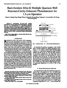
Figure 1: Schematic view of a typical aerosol impactor showing particle trajectories for different particle sizes collecting enough particle mass. A number of attempts have been made to develop airborne particle collectors with real-time monitoring capability. The main challenge in such system is aligning the aerosol jet stream with the microscale resonant device. In [6], airborne particles were deposited onto a film bulk acoustic resonator (FBAR) via thermophoretic precipitation technique. The particles were driven away from a heated surface and collected due to the gained kinetic energies. To align the thermophoretic module with the FBAR, an eight-piece assembly was implemented that required complicated assembly and suffered from low accuracy. In [7], a nanometer aerosol sampler (TSI 3089) was used as an electrostatic precipitator to trap charged engineered carbon nano-particles on a silicon resonant cantilever. This technique also requires complex and sophisticated instrumentation. This work presents a high precision real-time particle mass concentration monitor comprised of MEMS resonant mass balances [8] integrated within a custom made aerosol impactor. The resonator alignment challenge is resolved using a simple approach that will be described in the following sections.
KEYWORDS Aerosol impactor, MEMS resonator, micro alignment, mass balance, real-time mass measurements, particle mass concentration
INTRODUCTION Concentration measurement and size distribution analysis of airborne micro/nanoscale particles is of great interest to environmental scientists, and is required for monitoring of controlled environments such as cleanrooms and operating rooms. The majority of currently available particle monitoring systems detect particles based on reflection of light as particles pass through a laser beam. Such systems are however incapable of detecting particles below 100nm in diameter and do not provide adequate size distribution data. They also need integration of several optical components which make the overall system complex, costly, and bulky [1,2]. Inertial impaction, on the other hand, is an airborne particle sampling technique that can be used to collect and size segregate particles with dimensions down to a few nanometers. An impactor stage consists of a plate with one or multiple micro-orifices (nozzles) and an impaction substrate underneath the nozzles [3,4]. Jets directed onto impaction substrate are established by forming a partial vacuum on one side of the nozzles. Airborne Particles with diameters smaller than the stage cut-point (determined by flow rate, nozzle diameter and Stokes number [5]) flowing through the orifices escape collision with the impaction substrate, while particles larger than the cut-point will be deposited onto the impaction plate (Fig. 1). However, despite their versatility, conventional impactors cannot provide any real-time data and the impaction plates are to be weighed manually after
978-1-4673-5983-2/13/$31.00 ©2013 IEEE
T
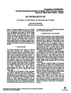
MEMS BALANCE DESCRIPTION Thermally actuated MEMS resonant structures were fabricated using the standard single mask process and used as highly sensitive mass balances. The fabrication process includes carving the structures out of the SOI device layer (by deep reactive ion etching) followed by removing the underlying buried oxide layer (BOX) in hydrofluoric acid (HF). Figure 2 shows the SEM view of a 5µm thick 2.87MHz dual plate thermally actuated resonant structure after airborne particle deposition. The short narrow beam connecting the two plates acts as both thermal actuator and piezoresistive sensor for operation of the device. Thermal actuation occurs by passing a fluctuating electrical current through the
661
Transducers 2013, Barcelona, SPAIN, 16-20 June 2013
Table 1: Design parameters Parameter
Value
ρp ρ µ Q P2 V0 W n
1000 1.2 1.81×10⁻⁵ 0.5 -21 83 0.25 2 0.47
√
can be collected if the particle slip correction is increased by operating the impactor at lower pressures. The most important characteristic of an impactor stage is, however, the collection efficiency curve, which indicates the percentage of particles of any size which are collected on the impaction plate as a function of the particle size. It is desirable for the efficiency curve to have a sharp division between the particles collected and those which are not [5]. As it can be seen on the collection efficiency curves in [5], the sharpness of cut is best for Reynolds numbers between 500 and 3000 which correspond to √ of 0.47. Reynolds number is a dimensionless number that quantifies the relative importance of inertial forces to viscous forces and is defined as
50µm
Figure 2: SEM view of a 5µm thick 2.87MHz dual plate thermally actuated resonant structure after particle deposition. actuator beam. The AC force generated in the beam as a result of the fluctuating temperature and therefore alternating thermal stress in the beam, can actuate the resonator in its in-plane resonant mode [9]. Modulation in the resistance of the same actuator beam due to the mechanical vibrations via the piezoresistive effect allows monitoring of the resonator vibration amplitude.
AEROSOL IMPACTOR DESIGN
(4)
The primary parameter that governs the collection of particles in an inertial aerosol impactor is the Stokes number, St, defined as [5]:
where , ρ is air density, Q is volumetric flow rate through the nozzles and n is the number of nuzzles. The impactor in this work is designed to have a flow rate of 0.5LPM and pressure difference of -21inHg across the nozzle attainable by a 2102X Dynaflo miniature pump. Selecting n and W to be 2 and 0.25mm, respectively, (4) will result in a Reynolds number of 1400. Recursively solving (2) and (3), with the parameters listed in Table 1, the cutoff size converges to 130nm.
(1) where ρp is the particle density, C is slip correction, V0 is the average air velocity at the nozzle exit, Dp is the particle diameter, µ is air viscosity and W is the nozzle diameter. Stokes number is a dimensionless parameter that can be used to predict whether a particle will impact on an impaction plate of stage or will follow the air streamline out of the impaction region and remain airborne (Fig. 1). Typically √ is defined as the value of √ corresponding to Dp50, which is the value of Dp collected with 50% efficiency. Thus [5]: √
√
Unit
kg/m3 kg/m3 kg/m.s LPM in Hg m/s mm -
Substituting
into (2), the following
equation is obtained. √
(2).
√
√
(6).
To achieve a different cutoff size with the same vacuum pump, n and W can be changed so that Re stays within the desired range. As it can be seen from (6), by increasing n while W is decreased, the cutoff size will have a lower value and vice versa. This approach can be used for successive stages in a cascade aerosol impactor to collect smaller particle sizes on the subsequent impaction plates. Further pressure drop in the subsequent impaction plates, which results in a larger slip correction, will also lead to an additional drop size in collected particles. The other two important physical parameters associated with impactor nozzles are jet to plate distance
The only two parameters in (2) which can be chosen to collect specific particle sizes are slip correction, C, and nozzle diameter, W. Cunningham slip correction factor can be found using [5]: (3) where P2 is static pressure at the impaction plate. Units for P2 and Dp are atm and µm, respectively. Smaller particles
662
(a)
(b)
Nozzle
(c)
Alignment Pin PCB
Resonator chip Lower chamber of impactor
Alignment Hole in PCB
Impactor Nozzle Plate
Figure 3: a) Bottom to top exploded views of the deigned aerosol impactor with embedded circuitry; b) Top to bottom exploded view of the system; c) Close-up view of the alignment pins in contact with the resonator chip from the backside of the PCB. (b)
(a)
Hole for bolt
(c)
Pump connection Bolts for holding pieces
Holes for inspection of Alignment Impactor outlet
Impactor nozzle (0.2mm)
Figure 4: Illustration of the assembly procedure. S and nozzle throat length T (shown in Fig. 1). As a design criterion, the jet to plate distance and the throat length should be at least equal to the nozzle diameter in order not to influence the cutoff characteristics. Also having a tapered inlet section for the nozzles is always recommended.
IMPACTOR FABRICATION ALIGNMENT TECHNIQUE
the PCB. Holes drilled in the PCB allow visual inspection of the position of the alignment pins with respect to the sample during assembly (Fig. 4b). After aligning the resonator chip with the impactor plate the two impactor parts and the PCB are fixed together using bolts (Fig. 4c).
AND
A single stage impactor with nozzle dimensions described above was machined out of aluminum (Figs. 3a, 3b, 4a). The nozzles that are the air inlets lie on the top plate while the outlet is embedded in the lower chamber. Face seal glands carved in the two parts along with Orings can seal the two parts on the two sides of the printed circuit board carrying the resonator chip. To align the microscale resonator underneath the nozzle, three precisely machined alignment pins are formed on the inner side of the impactor plate (Fig. 3c). Alignment is performed by pushing the pins against the edges of the resonator chip. To achieve perfect alignment, the position of the pins with respect to the nozzles on the impactor plate and that of the resonators on the silicon chip were carefully considered and matched in the designs. Furthermore, the silicon wafer was precisely diced into chips with predetermined exact dimensions (4mm×8mm).
ASSEMBLY RESULTS
AND
100µm
10µm
Figure 5: Optical microscope images of the resonator of Fig. 2 after airborne particle deposition.
MEASUREMENT
Figure 5 shows optical microscope views of the dualplate thermal-piezoresistive resonant balance of Fig. 2 after exposure to air flow through the impactor nozzle, showing a good alignment between the nozzle and the resonator. The slight misalignment (~30µm) could be due to the limited precision provided by machining process or
To perform the measurements, a resonator chip was placed in the designated location on the specifically designed PCB (Fig.4a) and one of the resonators on the chip was wire-bonded to the appropriate metal tracks on
663
-0.5 kHz/min
Laboratory
3
0.160µg/m
Gowning Room Area of Cleanroom
0.040µg/m -0.027 kHz/min
Laboratory
0.402µg/m
3
Cleanroom
0.024µg/m
3
-0.043 KHz/min
3
-0.2 kHz/min
Air Purifier
-0.05 kHz/min
3
0.03µg/m
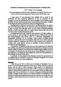
Figure 6: Real-time change in resonant frequency of the thermally actuated MEMS resonator of Fig. 2 during exposure to airborne particles in different environments with different particle concentrations. Misplacement of the assembled parts during tightening of the bolts. Air samples from four different sources, including the laboratory, an air filter, cleanroom and gowning area of the cleanroom were analyzed using the same impactor assembly. The resonant frequency of the resonator embedded in the impactor was carefully monitored over a period of 3 to 12 minutes in each environment. Figure 6 shows the collected frequency data over time. Clear shifts in the rate of change in frequency in accordance with the expected particulate mass levels in different environments, shows the capability of the implemented system for real-time monitoring of air-borne particle mass concentrations. Different shift rates obtained in the laboratory is due to the fact that it is not a controlled environment and the particle concentration can change due to various factors (e.g. number of users present in the lab). Taking impactor collection efficiency into account, the particulate mass concentrations in different air samples are estimated to be 0.402, 0.024, 0.032 and 0.040µg/m3 for regular laboratory, cleanroom, filtered air and gowning room, respectively. Assuming the average size of the deposited particles to be 500nm, the number of particles per cubic meter of the cleanroom air sample can be estimated to be 3.2×10⁵. The expected particle counts for particles larger than 200nm, based on ISO 14644-1 cleanroom standards, are 2.37×10⁶ and 2.37×10⁵, for class 10,000 and 1,000 cleanrooms respectively. This matches the expected class for the cleanroom where the tests were performed.
aligning microscale devices with aerosol impactor nozzles. Particle mass concentration data obtained from four different sources demonstrate the capability of the presented system for high precision real-time airborne particulate mass monitoring.
ACKNOWLEDGMENT This work has been supported by the National Science Foundation under SBIR grant #1214737.
REFERENCES [1] K. M. Davitt et al., “A compact aerosol sensor and spectroscopic sorting with UV LEDs,” in Proc. Optically Based Biol. Chem. Detection for Defense Conf., 2006, pp. 63980-989. [2] M. V. Panchenko et al., “Active spectral nephelometry as a method for the study of submicron atmospheric aerosols,” J. Remote. Sensing, vol. 29, no. 9, pp. 2567-2583, 2008. [3] K. R. May, “The Cascade Impactor: An Instrument for Sampling Coarse Aerosols,” Journal of scientific instruments, vol. 22, no. 10, pp.187-195, 1945. [4] V. A. Marple, K. L. Rubow, and S. M. Behm, “A microorifce uniform deposit impactor (MOUDI): Description, calibration, and use,” Aerosol Science and Technology, vol. 14, no. 4, pp. 434-446, 1991. [5] Marple, V.A. and Willeke, K., “Impactor design.” Atmospheric Environment, vol. 10, pp. 891-896, 1976. [6] J. P. Black et al., “MEMS-enabled miniaturized particulate matter monitor employing 1.6 GHz aluminum nitride thinfilm bulk acoustic wave resonator (FBAR) and thermophoretic precipitator,” in Proc. IEEE ltrasonics Symp., 2007, pp. 476–480. [7] H. S. Wasisto et al., “Airborne engineered nanoparticle mass sensor based on a silicon resonant cantilever,” Sens. Actuators B: Chem., vol. 180, pp. 77-89, 2013. [8] A. Hajjam, J.C. Wilson, and S. Pourkamali, “Individual airborne particle mass measurement using high-frequency micromechanical resonators,” IEEE Sensors Journal, vol. 11, no. 11, pp. 2883-2890, 2011. [9] A. Rahafrooz and S. Pourkamali, "High-frequency thermally actuated electromechanical resonators with piezoresistive readout," IEEE Transactions on Electron Devices, vol. 58, no. 4, pp. 1205-1214, 2011.
CONCLUSION Thermally actuated MEMS resonant mass balances were embedded within a custom made aerosol impactor for real-time mass concentration measurement of airborne particles in different environments. Alignment of the MEMS resonators with aerosol impactor nozzles was carried out using precisely machined pins formed on the inner side of the impactor plate. The outcome shows the devised technique is highly effective in accurately
664