1
Agent-based Distribution Circuit Automation Charles Vartanian, Member, IEEE, Dana Law, Member, IEEE, Paul Hines, Member, IEEE, Robert Yinger, Member, IEEE, Stephanie Hamilton, Ali Feliachi, Senior Member, IEEE
Abstract—This paper presents the results of efforts to (1) equip an existing utility distribution circuit with current automation and communications technology and to (2) develop an agent-based control scheme that can manage the distribution circuit in real time. The control scheme is being designed to increase the reliability and efficiency of the circuit by managing reactive power resources, distributed generators and switching devices in real-time according to agreed-upon operating goals. The agent-based control methods are being tested with models of an existing distribution circuit (the “Circuit of the Future”) at Southern California Edison, which has recently been retrofitted with an advanced protective scheme using multiple on-circuit fault interrupters with Intelligent Electronic Device (IED) relays, and a DG interconnection point. Additional planned retrofits on the Circuit of the Future will include a power electronics based dynamic reactive support device. Simulation results in this paper illustrate that the control methods managing and coordinating legacy and advanced devices can significantly improve the voltage profile, reduce losses and decrease restoration times relative to the existing control schemes. Index Terms—Power Distribution, Distribution Automation, Multi-agent systems
C
I. INTRODUCTION
entralized grid-operating systems can be easier to design and generally conform to current utility industry practice, but there are offsetting disadvantages. These include slower response times, inflexible predetermined switching schemes, limited robustness to failures, and limited physical and functional scalability. Utility operating systems that include Smart Agent based intelligent decentralized decision making may be able to react more quickly, isolate local problems with more discretion and higher isolation, may be more resilient to failure, and may facilitate interoperability and scalability. This paper presents results from system simulations that demonstrate the potential benefits of agent-based distribution circuit automation, and describes efforts at Southern California Edison (SCE) to update a distribution circuit with technology that will enable such an approach. This work was performed in part in support of the National Energy Technology Laboratory’s ongoing research in energy delivery and reliability under the RDS contract DE-AC26-04NT41817 and supported in part by the US Dept. of Energy under Award Number DE-FC26-06NT42793. Charles Vartanian, Stephanie Hamilton, Dana Law, Robert Yinger are with Southern California Edison, Rosemead, CA Ali Feliachi is with the Advanced Power and Electricity Research Center, West Virginia University, Morgantown, WV Paul Hines is with the National Energy Technology Laboratory and the College of Engineering, University of Vermont, Burlington, VT 05405. (e-mail:
[email protected]).
The current control algorithms are simple, but show potential to provide substantial benefits in terms of reducing customer outage time, reducing losses and improving the voltage profile within the circuit. The conceptual Smart Agent algorithm reconfigures a distribution circuit under post-fault emergency conditions to maximize load recovery, and manages controlled VAR sources to optimize circuit voltages during normal and emergency conditions. These conceptual application scenarios employ a combination of predictive and feedback control to calculate and implement control plans according to operating goals. Preliminary simulations, described in Section X, indicate that these algorithms will bring substantial benefits in terms of reducing losses and customer outages. The distribution model used for simulations in this paper includes a newly redesigned distribution circuit within the SCE service territory with advanced sensing, relaying, and switching capabilities. The circuit is SCE’s Avanti 12 kV “Circuit of the Future” (Avanti). This paper begins by describing the components and integrating systems used by SCE to implement the Avanti’s advanced protection scheme. With this existing SCE advanced distribution circuit as reference basis, the paper describes the expected benefits and challenges of integrating advanced operating devices concepts including agent-based controls within a distribution system to improve system performance. II. DISTRIBUTION CIRCUIT AUTOMATION AND SCE’S “CIRCUIT OF THE FUTURE” SCE’s Avanti circuit was the product of a design competition that SCE held in 2003 to develop a test platform for incorporating new distribution technologies and methods that increase reliability and safety, while controlling customer cost. The resulting Avanti circuit went online in 2007, and now serves 1,400 of SCE’s residential and business customers. The circuit currently incorporates several advanced devices and functionalities, while leaving room to incorporate even smarter devices and functionalities in the future. Below, we describe the circuit’s in-service advanced protection scheme that provides fast and highly discrete fault isolation. Following discussion of this existing functionality, several forward looking concepts are presented; load flow simulation of DG support of circuit voltage and post-fault load transfer concludes this section.
2
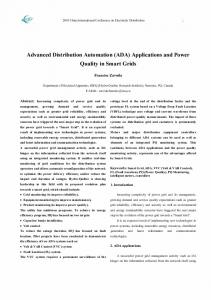
A. SCE’s Avanti Circuit, Improved Protection backend of the circuit to be manually picked up by one of the The automation scheme on the Avanti circuit consists of a adjacent tie circuits. central logic processor controlling multiple fast switching devices communicating via fiber-optic cable, in addition to a Utilinet radio network. The logic processor (SEL 2100), has been programmed with all reasonably possible failure scenarios, with an action for each. There are certain multiple failure scenarios that were not taken into account due to time limitations. The design team decided to limit the failure modes to n-2 conditions, since if all of the circuit relays failed to operate, the substation breaker would still trip, causing the whole circuit to go dead and turning the Circuit of the Future into the Circuit of the Present. The SEL 351S Remote Control Interrupter (RCI) controls and SEL 351R Remote Automated Recloser (RAR) control all communicate with each other Figure 1. Avanti circuit protection scheme through the SEL 2100 as well as with the substation gateway. While most of the logic is in the SEL 2100, there is still a Figure 1 illustrates the devices participating in the Avanti’s small amount in each one of the controls to be able to operate protection scheme which enables relatively faster and tighter in case the device loses communications with the SEL 2100. fault isolation, versus SCE’s current standard practice. Table During a fault, the SEL 2100 issues a “trip block” to all 1 identifies the key devices participating in the Avanti circuit devices upstream from the fault and allows only the affected protection scheme, and lists their current and potential-future relay to trip. After the relay has tripped, the SEL 2100 issues extended functionality. an “Isolation Open” to the next device downstream which isolates the fault between the two switches and allows the Table 1 – Avanti Circuit Protection Scheme Devices and Functions DEVICE/SYSTEM SEL 2100 SEL 351 R and S
Elastimold Vacuum Fault Interrupter w/Cleaveland Price Motor Operator Cleaveland Price Remote Control Switch Fiber Optic SEL 2407 Utilinet 900 MHz Radio
FUNCTION STANDARD/PROTOCOL Central processor. Permissive/block SEL Mirrored Bits relay scheme management Fault current trip. Instantaneous and SEL Mirrored Bits ToC options. SCADA Data capture. Fault break/isolation and circuit sectionalizing SCADA data capture. Load break and circuit reconfiguration. SCADA data capture. Relay-2100 communication GPS Time Clock No interaction with protective scheme. Used for remote-control distribution switch operation and SCADA polling.
While the Avanti has a finite number of failure scenarios that can be detected and corrected, the addition of Smart Agents could eliminate the need to try to consider every possible failure mode. Additionally, since Smart Agents are not hard-coded algorithms based on the individual configuration of each circuit, it becomes much easier to adapt the elements of the Avanti to other circuits on SCE’s system. Eliminating the need to develop logic from scratch each time
n/a
n/a
SEL Mirrored Bits GPS Metricomm carrying DNP 3.0
FUTURE EXTENSION Post-fault-clearing load transfer decision Incorporate GPS time stamp to enable 'PMU' type event recording; incorporate intelligence into device with circuit location information Participate in automatic load transfer scheme Participate in automatic load transfer scheme
PMU event recording, PMU Operations(angle check pretransfer) Establish comm link to allow DCMS to communicate with protection scheme devices for advanced/automated load transfer schemes
a new circuit is planned reduces the cost of planning a “smart” circuit down to levels approaching present circuits. Another potential improvement to the Circuit of the Future that could benefit from the introduction of Smart Agents is the concept of automatic reconfiguration. During present fault conditions, the device downstream of the fault is automatically opened by the SEL 2100, isolating the problem. However, the process of restoring power to the backend of the circuit is performed manually by an operator at the switching
3
center controlling a Remote Control Switch (RCS). This extra step in the load restoration process is to allow the operator to analyze adjacent circuits to make a decision as to which circuit will have the capacity to pick up the back end of the Avanti. To do this, historical load and ambient temperature curves are analyzed to find a previous day that closely resembles the current day in order to estimate how heavily loaded the circuit will be during the daily peak and whether it can support the extra load. Smart Agents would be able to analyze historical data much more quickly than a human and decide which, if any, tie circuit would be available to close into and restore power to the majority of the circuit. The communications network for the Avanti utilizes Schweitzer’s Mirrored Bits Protocol on the fiber for the highspeed communications and protection between devices as well as a proprietary Metricomm Protocol on SCE’s existing Utilinet radio system for device control. One of the key elements for protection in this system is the fiber-optic cable, which allows the devices to quickly communicate and isolate the fault. However, installing fiber-optic cable on every new circuit in the system would be cost-prohibitive. An alternative to the centralized control of the SEL 2100 would be to implement a Smart Agent in each one of the SEL 351 relays. The advantage of a decentralized control scheme would be a cost savings by having less equipment, as well as a decreased chance for complete failure should the controller fail. Ideally, centralized communication would not be necessary and each device would be able to monitor every other device and respond accordingly. This would only be possible if the device was able to know where it exists on the system and therefore detects what other devices are in the immediate vicinity. Granted, some sort of overall control system, such as SCE’s Distribution Control & Management System (DCMS), would still need to be in place in order to allow humans to conveniently interact with the system, but this would eliminate the need for a centralized controller (SEL 2100) on each circuit. If each device was able to receive a “ping” from the circuit breaker telling it which circuit it exists on, then a complete map can be created tracing the single switch all the way up to the generating station. During development of the Avanti circuit, SCE used load flow modeling to assess and scope several key components of the existing, and future envisioned, circuit. Load flow simulation was used to develop a performance specification for a dynamic reactive support device (planned for 2008 deployment), and to assess potential impacts of DG deployment on and adjacent to the Avanti. Two initial simple case studies using a load flow model of the Avanti and two adjacent circuits is presented to quantify the electrical distribution system impact of two conceptually advanced distribution system scenarios. The two scenarios are “DER and Voltage Support”, and “DER and Reconfiguration for Load Restoration”.
B. DER and Voltage Support SCE DER performed an earlier study that evaluated the beneficial impacts from connection of Distributed Generation (DG) DER with VAR capability to a distribution system. The reported findings from this earlier study [1] indicated that relatively large (MW-scale) DG with VAR capability will 1) reduce circuit losses, and 2) improve a circuit’s voltage profile. Using the Circuit of the Future load flow model, these earlier findings are again demonstrated in this report. Figure 2 illustrates a steady-state condition that meets SCE’s basic terms-of-service Tariff Rule 2 [2] requirement of maintaining steady-state bus voltages between 0.95 and 1.05 p.u.. In this initial case, without DG added, the average circuit voltages range from 0.96 – 0.99 p.u.. And the total calculated peak losses for the modeled three-circuit system is 0.77 MW. The attached Figure 3 shows the same system scenario, but with a 1 MW synchronous DG operating on the Avanti 12 kV circuit, and regulating its interconnection (12 kV) bus to 1.0 per unit. The voltages on the circuit with the DG operating had an improved range of 0.98 – 1.0 p.u., and the losses were reduced by -0.04 MW to 0.73 MW C.
DER and Reconfiguration for Load Restoration SCE’s existing practice for post-fault circuit reconfiguration for load restoration typically utilizes three types of isolating and/or switching devices: circuit breakers at the substation sending end of the circuit, fault-interruptingcapable normally closed remote controlled automatic reclosers (RAR) at circuit mid/interior-points, and normally open remote controlled switches (RCS) at outer-edge transfer points between circuits. In its most basic and typical implementation, this arrangement of devices allows for isolation of faulted sections through isolation of no more than half of the circuit, and then recovery and restoration of load to the unfaulted remaining half of the circuit. Without this arrangement, the whole circuit and all connected load is exposed to sustained outages for major circuit faults. One limitation is the available capacity on the receiving circuit. Figure 4 illustrates a load transfer that overloads the receiving circuit, and Figure 5 illustrates removal of this overload by addition of a participating DG providing 1 MW of output on the receiving circuit. The simple simulations presented here illustrate the potential to improve distribution system performance via use of participatory distributed resources. The control functionality was not explicitly modeled for these early study simulations. These simulations are simple ‘before and after’ load flow snapshots confirm potential beneficial impact of having new advanced device participate to help meet grid performance goals, such as improved circuit-level voltage profile, and mitigation of thermal overloads. These findings reinforce the author’s interest in gaining deeper understanding into the best means to implement a control environment that would support and enable these beneficial functionalities.
4
DG Off
0.96 p.u.
AVANTI 12 kV 0.99 p.u.
Figure 2. Avanti circuit without DG regulating voltage
DG On
0.98 p.u.
Figure 3. Avanti circuit with 1 MW DG regulating interconnection (12 kV) bus to 1 p.u.
1.0 p.u.
DG Off Open
Overloads
Closed
Figure 4. Avanti circuit load transfer, adjacent circuit overload (red circuit section, no DG on the Avanti 1
DG On
No Overloads
Figure 5. Avanti circuit load transfer, adjacent circuit overload mitigation with a 1 MW DG on the Avanti
1
The units for the values shown in Fig’s 4 & 5 are Amperes and percent of the circuit conductors’ emergency Ampacity ratings.
III. MULTI-AGENT CONTROL ALGORITHMS The communications, switching, and DER technology being implemented in the Avanti circuit provide an excellent test case for the design and testing of a Smart-Agent approach to real-time control. This section describes the two simple agent-based control algorithms for distribution circuit automation, which are being tested on models of the SCE Avanti and adjacent circuits. A. Control goals One characteristic that differentiates smart agents from simple control devices is preferences. Biological agents generally operate by choosing actions according to preferences rather than fixed sets of rules. Any set of preferences can be expressed as a set of goals, which can subsequently be written as an optimization formulation. This is roughly the approach used by economists to represent the decision-making process of humans and organizations. This approach is also useful in the design of smart-agent control systems. Clearly defining the goals of the system to be controlled can lead to clear methods for achieving those goals. The project team deemed the following goals to be relevant to distribution circuit operations: • Minimize the cost of serving existing load; • Minimize the cost of control actions (wear and tear on or damage to equipment); • When it is not possible to serve the entire existing load, serve as much load as possible, potentially weighted by relative priority among service locations; • Maintain the circuit’s voltage profile as close as possible to an operator-defined ideal profile. Other goals could be included in the above set, but these provide a good starting point for the design of our control agents. For the sake of simplicity, we divide these goals into two separate control problems, which could be assigned to two or more agents. The first problem attempts to schedule resources during normal operations. The second attempts to choose switching actions and other remedial actions to reconfigure the circuit after a fault. Section B describes the preliminary design for the agent-based control scheme; sections C and D describe the algorithms for scheduling and reconfiguration; and section E describes some anticipated future improvements to the algorithms, which will make the method more robust to failures and facilitate scalability. B. Preliminary design Our preliminary design is hierarchically organized. Two computational agents will be located at the distribution substation. The scheduling agent (SA) manages resource scheduling during normal operations. The reconfiguration agent (RA) calculates switching actions after a fault or some other unusual event. We also place a simple agent at each feeder or load switching device, switched capacitor or distributed generator. In the current hierarchical design, these agents simple respond to requests for measurement data, implement default control actions according to simple rules and respond to control commands from SA and RA. These
capabilities exist within the SEL relays being installed in the Avanti circuit. Using very simple (less-smart) agents at the actuator locations simplifies the design, and reduces costs, substantially. C. Real and reactive power resource scheduling The scheduling agent is responsible to ensure that the circuit operates according to agreed upon goals during normal operations. Its primary role is to schedule the distributed generator and capacitors to ensure a good voltage profile within the circuit and to minimize operating costs. The following formulation provides a convenient way to achieve these goals: n
(
Minimize C(G) + cV ∑ | Vi | −Vi G,V ,Y
i=1
)
n
Subject to S(Gi ,Di ,Vi ,Yi ) = Vi ∑ Iij* Iij = y ij (Vi − V j )
2
(1)
j=1
where C(G) represents the cost of supplying power to the circuit from local DGs and the grid, Vi represents the complex voltage at bus i. G and D give the generation and demand at each bus, Iij gives the complex branch current along the branch from bus I to bus j, and Yi gives the capacitance at bus i. The S(…) function provides the complex bus power injection given the various sources and sinks at each bus. The voltage cost term estimates the cost of deviating from the ideal node voltage ( Vi ). This formulation is roughly equivalent to the standard AC Optimal Power Flow problem, with the exception that the reactive power sources may be constrained to a discontinuous feasible set (they are switched rather than being continuously controllable), and the voltage constraints are expressed in the objective rather than as a hard constraint. In our preliminary design the scheduling agent runs its algorithm periodically (perhaps once per hour) to determine adjustments that should be made to switched capacitors and DG units. Once the SA has calculated a revised schedule it will send new set points to the DG and capacitor agents throughout the circuit. D. Circuit reconfiguration The circuit reconfiguration agent (RA) focuses on choosing branch switching actions to serve as much load as possible after a fault and a failure to re-close the circuit section. The agent may also be asked by the SA to reconfigure the circuit to alleviate branch current overload conditions within the circuit. The optimization formulation will be used to calculate control actions:
Maximize
⎛ n ⎞ ⎜ Di ⎟ − C(∆a) ⎝ i=1 ⎠
Subject to
Gi − Di = ∑ Fij
a,D,G
∑
n
(2)
j=1
Fij = aij bij (θ i − θ j ) Fij,min ≤ Fij ≤ Fij,max where Di and Gi are measures of the real power demand and generation, C(∆a) is the cost of switching actions (a represents branch statuses), Fij, aij and bij represent the current flow, branch status and susceptance of the branch between buses i and j. This formulation is roughly equivalent to the standard DC power flow, with the addition of the branch status variables. This addition causes the formulation to be non-linear and non-convex. Fortunately, given a large number M eqs. 3 and 4 below are both linear and equivalent providing a way to linearize the formulation.
−M(1− aij ) ≤ Fij − bij (θ i − θ i ) ≤ M(1− aij ) (3) −Fij,min aij ≤ Fij ≤ Fij,max aij
(4)
This problem can be solved for any distribution system using standard mixed integer linear programming tools. The output of the optimization algorithm will be a set of switching actions ( ∆a ) that will maximize the load served by the circuit. Once calculated the RA sends switching commands to the switch agents, who will enact the new circuit configuration and report back to RA regarding the new switch positions. If the reconfiguration is successful, the RA will signal the SA to calculate a new schedule for the circuit, given the revised configuration. 1) Illustrative results To illustrate the utility of the SA algorithm, we allow the SA to calculate a new schedule for the circuit after all capacitors have been switched out of the circuit. The resulting change in voltage profile is shown in Fig. 5. The resulting voltage profile is much closer to the 1.0p.u. goal and losses are reduced by about 0.5%.
Figure 6 – The voltage profile in the Avanti circuit, with 24 MW of demand, before and after capacitor switching according scheduling agent’s problem formulation.
E. Anticipated improvements to the control algorithms The algorithm described above relies on a very simple decomposition of the scheduling and reconfiguration problems. A better solution would allow the switching, DG and capacitor agents to self-coordinate their schedules. In future work we expect to build on the algorithms described in [3] and [4] to facilitate more autonomy in the switching and IV. CONCLUSIONS This paper describes the concept of improving operation of a distribution circuit of the future through installment of interoperable devices which are controlled using a multi-agent system approach. The controllable devices that are being deployed on SCE’s Circuit of the Future, Avanti 12kV, include IED-relay operated switches and fault interrupters, and DER. Through application of the technology and concepts presented in this paper, it is increasingly possible for the components of the T&D system to solve very difficult problems in real time, without needing to consult centrally located control centers. An agent-based design for coordinated real-time T&D control could bridge the gap between simple devices, such as relays, that use only local information to make quick decisions, and operator-based controls that require a lot of information and act along longer time horizons. While the concepts and results described in this paper are far from complete, they hopefully provide some guidance for the industry as it develops plans for future realtime control methods. V. ACKNOWLEDGMENT This material is based in part on work supported by the Department of Energy Office of Electricity Delivery and Energy Reliability under Award Number DE-FC2606NT42793. VI. DISCLAIMER This report was prepared in part as an account of work sponsored by an agency of the United States Government. Neither the United States Government nor any agency thereof, nor any of their employees, makes any warranty, express or implied, or assumes any legal liability or responsibility for the accuracy, completeness, or usefulness of any information, apparatus, product, or process disclosed, or represents that its use would not infringe privately owned rights. Reference herein to any specific commercial product, process, or service by trade name, trademark, manufacturer, or otherwise does not necessarily constitute or imply its endorsement, recommendation, or favoring by the United States Government or any agency thereof. The views and opinions of authors expressed herein do not necessarily state or reflect those of the United States Government or any agency thereof. VII. REFERENCES [1]
Hamilton S, Ang A., Hessenius C., “Fuel Cells: A Utilities’ Perspective,” Journal of Power Sources, vol. 158, no. 1, pp. 436-445, 2006.
[2]
Southern California Edison, “SCE Tariff Rule 2: Description of Service,” Online: http://www.sce.com/NR/sc3/tm2/pdf/Rule2.pdf.
[3]
Feliachi, A., Schoder, K., Ganesh, S., Lai, H.-J., ``Distributed Control Agents Approach to Energy Management in Electric Shipboard Power Systems,'' invited panel paper, IEEE Power Engineering Society General Meeting, Montreal, Quebec, Canada, June 18-22, 2006.
[4]
P. Hines, “A decentralized approach to reducing the social costs of cascading failures,” Ph.D. thesis, Carnegie Mellon University, 2007.
V. BIOGRAPHIES Charles Vartanian is Project Manager for DER Development at SCE’s Distributed Energy Resources group (DER). Charlie is the primary technical liaison for the group supporting joint technical research studies with external entities. These studies are actively evaluating how to best integrate and leverage DER assets for future utility grid benefit. Before this assignment, Charlie worked for SCE’s Transmission & Interconnection Planning group. Charlie received his MSEE from USC, and his BSEE from Cal Poly Pomona. Charlie is a licensed Professional Engineer in California, and is a member of IEEE. Dana Law is an engineer in the Field Technologies group at SCE, working on exploring safer and more efficient ways for field workers to do their job. He has also been involved with the design and implementation of SCE’s Circuit of the Future, as well as exploring RFID technology for utility use. Dana received his BSEE from The University of Southern California and is a member of IEEE. Paul Hines is an Assistant Professor in the School of Engineering at the University of Vermont (UVM). He received the Ph.D. degree in Engineering and Public Policy from Carnegie Mellon University in 2007 and the M.S. degree in Electrical Engineering from the U. of Washington in 2001. Formerly he worked as a Research Scientist at the National Energy Technology Laboratory, for the Federal Energy Regulatory Commission, where he studied interactions between nuclear power plants and transmission networks, for Alstom ESCA, where he designed a short-term load forecasting tool and for Black and Veatch, where he worked on substation design projects. His main research interests are in the areas of complex systems and networks, the control of cascading failures in power systems and energy system reliability. Robert Yinger is a Consulting Engineer in SCE’s Engineering Advancement Group. In his 30 years with SCE, Bob has been involved in a wide range of research and development activities including subtransmission planning, solar and wind energy development, power quality, peer-to-peer radio development, electronic metering systems, and substation automation. His present work includes investigation of the effects of air conditioner stalling on system voltage, advanced metering, and new automation technologies for substations and the distribution system. Bob received his BSEE from California State University, Long Beach. He is a licensed Professional Engineer in California and a member of IEEE. Stephanie Hamilton is in charge of Distributed Energy Resources for SCE. At SCE, Ms. Hamilton oversees a diverse portfolio R&D of new and emerging DER technologies, such concentrating solar, fuel cells, microturbines and balance of plant components such as inverters. Previously Ms. Hamilton held energy positions at some of the largest utilities in the US in both natural gas and power in both their regulated and unregulated subsidiaries, including Southern California Gas, Public Service New Mexico, and Grant County PUD. Ms. Hamilton holds an MBA and a BS in Mechanical Engineering and is widely published on energy and energy-related issues. Her latest book is The Handbook of Microturbine Generators. Meanwhile, she is an original member of DOE’s 13-member GridWise Architecture Council which is focused on increasing interoperability in the North American power industry. Ali Feliachi is the holder of the endowed Electric Power Systems Chair in the Department of Computer Science & Electrical Engineering and the Director of the Advanced Power & Electricity Research Center at West Virginia University. He obtained MS and PhD degrees in Electrical Engineering from Georgia Tech. Following graduation he held a postdoctoral position at Georgia Tech and was a consultant to Georgia Power Co. His research interests are control, modeling and simulation of electric power systems.