This paper focuses on the multi-agent highway traffic sim- ulation. It provides a realistic .... The highway is divided into same sized segments, where each ...
Agent-based Highway Traffic Simulation Jiˇrí Vokˇrínek, Jan Jiránek, Jiˇrí Hodík Agent Technology Center Department of Cybernetics FEE, Czech Technical University in Prague
{vokrinek}@agents.felk.cvut.cz
ABSTRACT This paper focuses on the multi-agent highway traffic simulation. It provides a realistic modeling with high fidelity continuous vehicle movement incorporating physical dynamics of the vehicles. The deliberative agent part of the system enables to implement and evaluate complex cooperation and coordination algorithms. The paper presents the architecture and implemented simulator for evaluation of a wide scale of non-cooperative and cooperative vehicles driving behaviors and intelligent highways.
Keywords simulation, highway traffic
1.
INTRODUCTION
The amount of vehicles whether it concerns personal vehicles or trucks and insufficient highway networks capacity cause serious problems in modern time. Based on statistical information, lot of car accidents occur everyday and the number of accidents is still fast increasing. These are the reasons for demands for design and development intelligent highway systems, which would be able to solve these problems on existing highway infrastructures. Since 90s there is the research trend, which is aimed at developing more or less automated and autonomous systems,which focus on safety and prevention or reduction the accidents, on existing highways. Some of the researches and theirs experimental demonstrations experience that there is possible to achieve these goals in given situations. Their logical result is that the capacities of highways are used inefficiently, because of controlling by humans. They usually don’t cooperate with the others and they have very limited or late knowledge about an environment. This brings the opportunity to design an automated controlling unit, which enhances these features. The multi-agent platform is suitable for design such systems.
This article contains unpublished work. Do not redistribute. Unpublished article Copyright 2010 Agent Technology Centre.
This paper presents the agent-based highway traffic simulation framework with high fidelity of vehicles movement modeling. The system supports validation and evaluation of various vehicle control mechanisms, such as non-cooperative drive, cooperative drive and information propagation, and intelligent highway systems.
1.1
Related Work
One of the famous and pioneering experimental system is the project Automated Highway System (AHS) [2], which is based on vehicle platooning. The platoon is a line of vehicles successive driving together and exchanging information about their actual states (e.g. speed and acceleration) with each other. In the case of necessity of turning maneuver, vehicles negotiate with each other to guarantee safety and smooth lane change. AHS was developed by researchers at the California PATH program and was demonstrated in San Diego on National Automated Highway System Consortium (NAHSC). The eight-vehicle platoon demonstration successfully demonstrated the technical feasibility of operating standard automobiles under precise automatic control at close spacing at highway speeds. The main problem of real world implementation of AHS is the need the construction of special joining lanes, by which new vehicles going to existing platoon would join to traffic. The Advanced Cruise-Assist Highway System Research Association (ASHRA) [3], was created by twenty-one private participating companies in the fields of automobile manufacturing, electronic, and telecommunications to oversee research and development of AHS road infrastructure. The association conducts a three-phased program: i) danger warning (AHS-i), ii) assistance for driving (AHS-c), and iii) automated highway system (AHS-a). ASHRA is a system, which detects, recognizes the road traffic environment, feeds back them to drivers in real time in one of three levels: information offer, control assist, and automated driving. Probably the most high-profile vehicle automation project in Europe in recent years has been Chauffer [4], which has implemented electronic tow-bar operations for heavy trucks. The project demonstrated basic capability on public highways in Germany, in which a lead truck (manually controlled) was followed by a second truck under fully automated control. This was accomplished with radar-sensing, infrared signatures and vehicle-vehicle communications. The project have shown that this type of operation can increase fuel economy (up to 20%) and reduce the traffic impediments caused by trucks (up to 8% improvement in capacity). Chauffeur II [4] concntrates to implementing the capability to entrain behind any type of vehicle and also platoon mul-
tiple trucks. There are two main differences between AHS and Chauffeur – Chauffeur specialization is only on trucks and human controls its lead vehicle. Before applying any drive control system to the real traffic, there is a need of experimental validation in simulated environment. Classical approaches of traffic simulation are based mainly on cellular automata (CA) [1]. CA is a discrete model in time, space, and state variables. It consists of a regular grid of cells, each in one of a finite number of states. For each cell, a set of cells called its neighborhood is defined relative to the specified cell. CA models are very efficient in large-scale network simulations, due to their simple design. This paper focus on continuous vehicle movement simulation that the CA is not able to provide in conjunction with agent-based driver behavior modeling that supports a large scale of autonomous deliberative models.
2.
TRAFFIC SIMULATOR
This section introduces the architecture of highway traffic simulator. It consists of highway model representation, model of objects (entities in the environment), and visibility modeling in the environment.
2.1
Highway representation
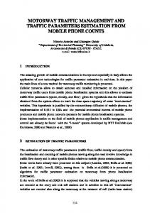
A typical road usually consists of several types of curves, lines and arches. For their representation we have decided to use B´ezier splines. It is universal solution and is known in computer graphics to model smooth curves. A B´ezier spline is a spline curve where each polynomial of the spline is in B´ezier form. In other words, a Bezier spline is simply a series of B´ezier curves stacked end to end where the last point of one curve coincides with starting point of the next curve. Because of polynomial equation of each Bezier curve, it is easy and efficient to calculate any point on this curve. Quadratic and cubic B´ezier curves are most common; higher degree curves are more expensive to evaluate. When more complex shapes are needed, low order B´ezier curves are patched together. There is used Cubic B´ezier curve as highway representation in this simulation. Four points P0 , P1 , P2 and P3 in the plane or in threedimensional space define a cubic B´ezier curve (see Figure 1). The curve starts at P0 going toward P1 and arrives at P3 coming from the direction of P2 . Usually, it will not pass through P1 or P2 ; these points are only there to provide directional information. The distance between P0 and P1 determines “how long” the curve moves into direction P2 before turning towards P3 . The main shape (represented by axis) of each highway is generated by B´ezier spline and all these highways form together whole highway network. To guarantee smoothness, the control point at which two curves meet and one control point on either side must be collinear. Every highway has at least one lane; lanes are parallel to main axis spline in xy plane. The bank of the whole highway is not included.Because vehicle is moving only on a highway, distance of vehicle from the start of this highway determines its position. Calculation of position as of real point in 3D world (coordinates x, y, z). We get position of vehicle from its distance by cast distance to polynomial form of spline. A position of a vehicle is specified by two types of distances, first is the distance between start of the highway and vehicle centre (distance) and second is the distance between the main axis and vehicle centre (distLane). Figure 2
Figure 1: The highvay representation based on the B´ ezier curve. The B´ ezier curve in the 3D space (a) and the sample of highway crossing (b).
Figure 2: Details of highway and its lanes. The representation of vehicle position on the highway (left) and the lane change (middle and right).
shows the vehicle position representation and the change of the lane. The vehicle increases it’s distLane position and thus effectively changes the lanes. There are a lot of objects on a highway network. Some objects are static, such as blocks and signs, some are dynamic – vehicles. A highway can be very long and vehicles are positioned on it differently in various distances. Because of this, we require to have reliable data representation of a whole highway to know exact position of each vehicle and also getting object in a visibility range for every vehicle placed on the highway. The simulated highway system is divided into segments and each object belongs to one segment at one time. The highway is divided into same sized segments, where each segment is represented by one cell of the hash-table. The hash function is based on the position of the vehicle on the highway segment, so each vehicle is then able to get information about near vehicles by accessing surrounding cells in the hash-table. See Section 2.3 for more details.
2.2
Object model
There are following types of objects in the highway simulation: • Blocks: A block is a static object on a highway; it represents an obstacle. One goal of the vehicle logic is to bypass all obstacles placed on highways and avoid collisions with them. • Signs: A sign is a static object and it has control function; it is not an obstacle. Every sign is assigned to a highway and the vehicles can see the signs and adapt it’s driving behavior using the information placed on the sign. • Vehicles: There are a lot of types of vehicles in real world. Besides these, there are a lot of types of drivers as well. There are four types of cars (physical models) implemented in the presented highway simulation system: TYPICAL, SPORT, F1, TRUCK with corresponding physical parameters of the model. Each vehicle is equipped by the agent responsible for the deliberative behavior (driving, communication and coordinations with others, etc.)
2.3
The Visibility
Each Vehicle Agent has defined its visibility ranges. In front of the vehicle there is the front visibility, behind the vehicle there is the rear visibility. If a object is within a visibility range of a vehicle, Vehicle Agent can see it, so the object is added to a visibility list of the Vehicle Agent. The visibility is very important for all vehicle logic. The vehicles act on the basis of locations and behaviors of visible objects. Generally, there are two types of vehicle visibility, the influence visibility and the communication visibility. The former one covers up all visible objects, which can influence the actual vehicle. For example the vehicle c3 on the Figure 3 is in visibility range of the vehicle c0, but this vehicle can not influence the vehicle c2. But still the c3 can communicates with vehicle c2. It is within its communication visibility range. An influence of a object on an actual vehicle is judged in the logic of the Vehicle Agent. All objects without influence are filtered out to improve the
Figure 4: The example of the visibility on the highway slip-road (left) and two parallel highways (right) computational performance. They can be used only in cooperative mode for interactions (i.e. communication). If the visibility range is too short in relation to speed of the vehicle, the vehicle could act too late (for example a vehicle has a distance of front visibility less than its breaking distance). The visibility of the vehicles is determined using highway representation depicted in Section 2.1 and it is not based on actual world position. The representation capture the highway segment interconnection and the crossing, slip-roads or exit-roads. The Figure 4 shows the visibility on the slip-road and parallel highways (in this case, the vehicles cannot influence each other). On the slip-road (left part of Figure 4) the vehicle 0 should see vehicle 2, because it is in his visibility range, even it is on different highway segment. It also can see the vehicle 1 on a slip-road. So the vehicle 0 can see both vehicles, even they are in different highway segments and hash tables. In case of parallel highways (right part of Figure 4) the vehicle 0 is able to see vehicle 2 like in previous example, but it is not able to see the vehicle 3 because those highway segments are not interconnected in the highway representation.
2.4
Vehicle Logic
There are many different vehicles on a highway. Each of them acts somehow according to its logic. The logic determines behavior of the vehicle and reaction to critical situations. We distinguish cooperative and non-cooperative logics. Their main difference is in communication and interaction. Non-cooperative vehicles do not interact with other vehicles. They do not use negotiations with other vehicles. Cooperative vehicles are able to interact with the other cooperative vehicles. The vehicle logic module (see Figure 5) serves as a Vehicle Agent interface providing visibility information and applying the movement strategies in the simulation. The pure logic is captured by the Vehicle Agent described in the next section.
3.
IMPLEMENTATION
The multi-agent simulation consists of individual autonomous entities – agents, which are using reciprocal coordination, cooperation and shared knowledge. The system has been implemented using A-globe[5] agent platform enriched by the JBullet1 physics library for rigid-body modeling of the 1
JBullet (http://jbullet.advel.cz/) is Java port of Bullet
Figure 3: The visibility representation on the highway and the contents of highway segments hash-tables.
Figure 5: The vehicle logic module. vehicles. Architecture of the system is Server-client type (see Figure 6 for more details). The central system element is server type container and it is also the server for GIS Service. The server communicates with registered client’s containers by means of this service. The client containers represent vehicles running on highway network. There is possibility to place up to 50 Vehicle Agents to each client container. Each Vehicle Agent is individual module, which has own logic and algorithms.
3.1
Server
There are three agents on a central container. • Highway Agent is a central agent with responsibility for creation global environment, such as network of highways, blocks and signs on it, data collection and processing, simulation management and its controlling. It also models physical movement behavior of the vehicles and their interactions with the environment. • Visio Agent cares for 2D or 3D visualization. HighPhysics Library (http://bulletphysics.org)
Figure 6: The architecture of agent-based highway simulator. way Agent sends update topics to Visio Agent, for updating position in visualization. • Detail Agent shows 2D visualization with all detail of movement and strategy and information about actual chosen client Vehicle Agent. It is used for measurement global variables of whole simulation, because it has shown all global information.
3.1.1
Highway Agent
It is main server type unit, which controls the whole simulation. It provides all world information, holds all highways and objects, and it is responsible for running whole system. Its main tasks are: creation of server container, simulation configuration, control simulation run, and communication with Visio and Detail Agents and maintaining all Vehicle Agents placed on client’s containers. It is also responsible for global movement of local copy of each vehicle. It means, the server has all information of each vehicle stored in server’s local list. Every Vehicle Agent sends to Highway Agent his planned strategy (acceleration, direction and other parameters). Highway Agent receives its strategy and applies appropriate steering in the physics engine. The Highway Agent ˇ lists. holds all highways and their hashSs
3.1.2
Visio Agent
Figure 7: The screenshot of Visio Agent.
Figure 8: The example of the tested highway system.
The function of this agent is evident from its name. It starts after initialization of the simulation and is responsible for data gathering for visualization of simulation. Visio ˇ messages as well. These messages Agent processes systemSs receive from Highway Agent in each cycle and contain vehicle’s updates (positions, angles, and visual parameters). Figure 7 shows the screenshot of the Visio Agent.
vehicle in hash map on Highway Agent and then sends topic to relevant Vehicle Agents to update its local instance. After that, it traverses the list again and sends visibility to each vehicle. At the end of the loop Highway Agent sends time topic to all agents. Highway Agent receives upˇ update dates from each Vehicle Agent. Each this vehicleSs contains a calculated planned strategy, which includes acceleration, direction and other variable parameters for next time tick, for next loop cycle.
3.1.3
Detail Agent
The function of this agent is to visualize data of actual chosen Vehicle Agent. It shows details about chosen strategy, actual parameters of vehicle, visibility and even global simulation parameters for measurement.
3.2
Clients
The next important part of whole simulation is client side. The client’s containers contain Vehicle Agents.
3.2.1
Vehicle Agent
The Vehicle Agents represents dynamic vehicles, running on this highway network. Each Vehicle Agent has own unique address for communication, and logic as well and works as independent unit. The Vehicle Agents communicate with the Highway Agent and in case of cooperative mode with each other. The communication itself is facilitated by the client’s containers. The interaction of the Vehicle Agent with the highway environment is influenced by the type of its car (its physical model) and type of its driver (its behavioral model). The communications between all agents are made by sending and receiving topics and messages.
3.3
The simulation thread
The simulation thread is an infinite loop. It traverses whole list of vehicles and does following for each vehicle in this list. At the beginning it calls move method, which updates local instance of vehicle in Highway Agent. The moveˇ movement along its actual ment method involves vehicleSs highway, it is placed on. The movement updates position, angles and distance moved. It updates that depending on actual acceleration and direction and other variable parameters received from its Vehicle’s Agent. Then update this
4.
VALIDATION
The multi-agent highway simulation system has been validated on the series of scenario. We have implemented noncooperative rule-based Vehicle Agent behavior and basic cooperative behavior. The example of the tested highway system is depicted on Figure 8. In this article we are not focusing ont he exact measurement of the implemented methods (the methods serv as the baseline for future improvements), but to the demonstration of the highway simulator capabilities (the example of the influence of the Vehicle Agents cooperation is captured by Figure 9). There are many parameters that can influence a traffic flow – the parameters of an individual vehicle and the parameters related to highway system. The parameters of the individual vehicles are relevant for evaluation of the driving strategy. Whereas the data related to a highway are very useful to its regulation and global influence of the vehicles to the traffic flow. The parameters of the simulation are follows: • Number of vehicles – the total number of vehicles in the simulation. • Number of blocks – the total numbers of blockades in the simulation. • Control signs – the control signs on the highways. • The highway structure – the highway system. Every highway has its properties (length, width of lane, number of lanes, etc.). The measured parameters of an individual vehicle are:
2. Perform collisions avoidance: maintain safe distance from the vehicle in the front. If the distance to the vehicle in the front if lower than safety distance try to change the lane. If the vehicles stay in the lane, reduce the speed to keep the safety distance. 3. Error application with constant probability to controlling. The speed determined from previous rules is decreased with probability p. This simulates incorrect estimation of safety distance to the vehicle in the front, which can cause unnecessary breaking. The first rule involves driver’s desire to drive as fast as possible. The second rule encodes the interactions between vehicles. These interactions occur to collision avoidance. The third rule is for achievement of more realistic simulation similar to real traffic flow. Figure 9: The comparison of the traffic flow on the partially blocked highway for non-cooperative (negotiation disabled) and cooperative (negotiation enabled) modes. • Status – the vehicle can be in three types of status. It can move, be crashed or stopped. • Average speed – average speed of the vehicle.
4.2
Cooperative Driving
For the comparison we have implemented the basic negotiationbased cooperation. In this mode, each vehicle negotiate with its neighborhood about its intentions (e.g. lane changes, acceleration, decelerations). The vehicles than adapt their behavior with respect to agreed actions – e.g. in case of lane change the vehicles can adapt the speed in advance to avoid the need to break. The method helps the vehicles synchronize the speeds and improve the lane changing.
• Moved distance – the total moved distance. • Time of driving – the number of simulation periods elapsed without crash. • The total number of accelerations – total number of simulation steps when the vehicle accelerate. • The total number of breaks – total number of simulation steps when the vehicle break. • The total number of left passing – total number of simulation steps when the vehicle changes the lane to the left. • The total number of right passing – total number of simulation steps when the vehicle changes the lane to the right. The measured parameters of the highway segment are: • Total capacity – the number of vehicles per meter per lane. • Average flow – the number of vehicles per hour on the highway. • The rate between input speeds and output speeds (the input speed is the speed, which the vehicle has when it enters to the highway segment, output speed is the speed, when the vehicle leaves the highway segment).
4.1
Non-cooperative Rules
The simplest rule set, which leads to a almost realistic behavior, consists of three following rules applied at the same time to every vehicle: 1. Accelerate to the maximal possible speed.
5.
CONCLUSION AND FURTHER WORK
The presented multi-agent highway simulation provides a realistic highway traffic modeling with high fidelity continuous vehicle movement simulation incorporating physical dynamics of the vehicles. The deliberative agent part of the system enables to implement and evaluate complex cooperation and coordination algorithms. The future work will address the effective and robust noncooperative and cooperative methods for safe and reliable highway traffic control and driving behaviors.
6.
REFERENCES
[1] Cellular automata. In http:// mathworld.wolfram.com / CellularAutomaton.html. [2] California path - partners for advanced transit and highways: Vehicle platooning and automated highways. In http:// www.path.berkeley.edu / PATH / Publications / Media / FactSheet / VPlatooning.pdf, 1997. [3] Advanced cruise-assist highway system research association. In http:// www.ahsra.or.jp / index e.html, 2007. [4] T. Benz, A. Braun, U. Ulken, M. Schulze, J. Schwarz, , and J. Sonntag. Chauffeur - tr 1009 - report on safety analysis of system components and hazard analysis of tow-bar. In ftp:// ftp.cordis.europa.eu / pub / telematics / docs / tap transport / chauffeur d7.1.1.pdf, 1999. ˇ sl´ [5] D. Siˇ ak, M. Rollo, and M. Pˇechouˇcek. A-globe: Agent platform with inaccessibility and mobility support. In M. Klusch, S. Ossowski, V. Kashyap, and R. Unland, editors, Cooperative Information Agents VIII, number 3191 in LNAI. Springer-Verlag, Heidelberg, September 2004.