International Journal of Software Engineering and Knowledge Engineering, Vol. 11, No. 3, pp.1-24, 2001.
Agent UML: A Formalism for Specifying Multiagent Software Systems Bernhard Bauer, Jörg P. Müller, J. Odell Siemens AG, Corporate Technology, Information and Communications, D-81730 München, Germany [bernhard.bauer|
[email protected]]
Abstract. To gain wider acceptance for the use of agents in industry, it is a necessity to relate it to the nearest antecedent technology (object-oriented software development) and to introduce appropriate artifacts to support the development environment throughout the full system lifecycle. We address both of these requirements by presenting AGENT UML, the Agent UML (Unified Modeling Language) — a set of UML idioms and extensions. This paper provides an AGENT UML representation of the internal behavior of an agent; it then relates this internal description to the external behavior of the agent by using and extending UML class diagrams and by describing agent interaction protocols in a new way. Our claim is that by extending the de-facto standard representation for object-oriented modeling to agents, the learning curve for object-oriented developers to adopt aspects of agent-based programming becomes much less steeper. Thus, agent-oriented programming as a whole will become more amenable to mainstream software engineering
1 Introduction For the past decade, research on agent-oriented software engineering had suffered from a lack of touch with the world of industrial software development. Recently, it has been recognized that the use of software agents is unlikely likely to gain wide acceptance in industry unless it relates to de facto standards (object-oriented software development) and supports the development environment throughout the full system lifecycle. Successfully bringing agent technology to market requires techniques that reduce the perceived risk inherent in any new technology, by presenting the new technology as an incremental extension of known and trusted methods, and by providing explicit engineering tools to support proven methods of technology deployment. Applied to agents, these insights imply an approach that: • introduces agents as an extension of active objects: an agent is an object that can say "go" (flexible autonomy as the ability to initiate action without external invocation) and "no" (flexible autonomy as the ability to refuse or modify an external request)1; • promotes the use of standard representations for methods and tools to support the analysis, specification, and design of agent software. The former aspect of our approach leads us to focus on fairly fine-grained agents. More sophisticated capabilities can also be added where needed, such as mobility, mechanisms for 1
See [15, 19, 21] for more comprehensive definitions of agents.
representing and reasoning about knowledge, and explicit modeling of other agents. Such capabilities are extensions to our basic agents—we do not consider them diagnostic of agenthood. To achieve the latter, three important characteristics of industrial software development should be addressed: 1. The scope of industrial software projects is much larger than typical academic research efforts, involving many more people across a longer period of time. Thus, communication is essential; 2. The skills of developers are focused more on development methodology than on tracking the latest agent techniques. Thus, codifying best practice is essential; 3. Industrial projects have clear success criteria. Thus, the ability to trace and track progress from initial requirements to final deliverables is essential. The Unified Modeling Language (UML) is gaining wide acceptance for the representation of engineering artifacts in object-oriented software. Our view of agents as the next step beyond objects leads us to explore extensions to UML and idioms within UML to accommodate the distinctive requirements of agents. To pursue this objective, recently a cooperation has been established between the Foundation of Intelligent Physical Agents (FIPA) [10] and the Object Management Group (OMG). As a first result of this cooperation, we analyzed the requirements for such an endeavor and proposed the framework of AGENT UML [1, 2, 3 , 4]. In this paper, we summarize core parts within AGENT UML, i.e., mechanisms to model protocols for multiagent interaction and an extension of class diagrams for agents. This is achieved by introducing new class of diagrams into UML: protocol diagrams and agent class diagrams. Protocol diagrams extend UML state and sequence diagrams in various ways. Particular extensions in this context include agent roles, multithreaded lifelines, extended message semantics, parameterized nested protocols, and protocol templates. An agent class diagram extends usual class diagrams with agent specific information. The paper is structured as follows: In Section 2, we survey approaches to software specification, including UML. Section 3 specifies the extension of UML by multiagent interaction protocols. Section 4 discusses further details of the extensions. Class diagrams are revisited in section 5. Section 6 attempts a preliminary evaluation of the concepts, summarizes the results of the paper and discusses future research topics.
2 Software Specification Techniques AGENT UML is an attempt to bring together research on agent-based software methodologies and emerging standards for object-oriented software development.
2.1 Methodologies for agent -based software development There is a considerable interest in the agent R&D community in methods and tools for analyzing and designing complex agent-based software systems, including various approaches to formal specification (see [14] for a survey). Since 1996, agent-based software engineering has been a focus of the ATAL workshop series and was the main topic for MAAMAW’99 [12]. Various researchers have reported on methodologies for agent design, touching on representational mechanisms as they support the methodology. Our own report at [24] emphasizes methodology, as does Kinny's work on modeling techniques for BDI agents [17, 18]. The close parallel that we observe between design mechanisms for agents and for objects is shared by a number of authors, for example, [7 9]. The GAIA methodology [26] includes specific recommendations for notation in support of the high-level summary of a protocol as an atomic unit, a notation that is reflected in our
recommendations. The extensive program underway at the Free University of Amsterdam on compositional methodologies for requirements [13], design [6], and verification [16] uses graphical representations with similarities to UML collaboration diagrams, as well as linear (formulaic) notations better suited to alignment with the UML meta-model than with the graphical mechanisms that are our focus. Our discussion of the compositionality of protocols is anticipated in the work of Burmeister et al. [8]. Dooley graphs [23] facilitate the identification of the character that results from an agent playing a specific role (as distinct from the same agent playing a different role). The wide range of activity in this area is a sign of the increasing impact of agent-based systems, since the demand for methodologies and artifacts reflects the growing commercial importance of agent technology. Our objective is not to compete with any of these efforts, but rather to extend and apply a widely accepted modeling and representational formalism (UML) in a way that harnesses their insights and makes it useful in communicating across a wide range of research groups and development methodologies. 2.2 UML The Unified Modeling Language (UML) [20] unifies and formalizes the methods of many objectoriented approaches, including Booch, Rumbaugh (OMT), Jacobson, and Odell. It supports the following kinds of models: • use cases: the specification of actions that a system or class can perform by interacting with outside actors. They are commonly used to describe how a customer communicates with a software product. • static models: describe the static semantics of data and messages in a conceptual and operational way (e.g., class and package diagrams). • dynamic models: include interaction diagrams (i.e., sequence and collaboration diagrams), state charts, and activity diagrams. • implementation models: describe the component distribution on different platforms (e.g., component models and deployment diagrams). • object constraint language (OCL): a simple formal language to express more semantics within an UML specification. It can be used to define constraints on the model, invariant, pre- and post-conditions of operations and navigation paths within an object net. In this paper, we propose agent-based extensions to four following UML representations: packages, templates, sequence diagrams and class diagrams. 2.3 A rationale for AGENT UML In previous papers, we have argued that UML provides an insufficient basis for modeling agents and agent-based systems [1, 2, 3], see also [22]. Basically, this is due to two reasons: Firstly, compared to objects, agents are active because they can take the initiative and have control over whether and how they process external requests. Secondly, agents do not only act in isolation but in cooperation or coordination with other agents. Multiagent systems are social communities of interdependent members that act individually. To employ agent-based programming, a specification technique must support the whole software engineering process—from planning, through analysis and design, and finally to system construction, transition, and maintenance. A proposal for a full life-cycle specification of agent-based system development is beyond the scope for this paper.
The subset was chosen because agent interaction protocols (AIP) and agent class diagrams representing the internal agent behavior and relating it the external behavior are complex enough to illustrate the nontrivial use of and are used commonly enough to make this subset of AGENT UML useful to other researchers. AIPs are a specific class of software design patterns in that they describe problems that occur frequently in multiagent systems and then describe the core of a reusable solution to that problem [11, p. 2]. The definition of interaction protocols is part of the specification of the dynamical model of an agent system. In UML, this model is captured by interaction diagrams, state diagrams and activity diagrams. • Interaction diagrams, i.e. sequence diagrams and collaboration diagrams are used to define the behavior of groups of objects. Usually, one interaction diagram captures the behavior of one use case. These diagrams are mainly used to define basic interactions between objects at the level of method invocation; they are not well-suited for describing the types of complex social interaction as they occur in multiagent systems. • State diagrams are used to model the behavior of a complete system. They define all possible states an object can reach and how an object's state changes depending on messages sent to the object. They are well suited for defining the behavior of one single object in different use cases. However, they are not appropriate to describe the behavior of a group of cooperating objects. • Activity diagrams are used to define courses of events / actions for several objects and use cases. The work reported in this paper does not suggest modifications of activity diagrams. • Class diagrams describe the static semantics of data and messages in a conceptual and implementational way.
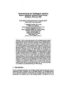
3 AGENT UML Interaction Protocols The definition of an agent interaction protocol (AIP) describes • a communication pattern, with • admissible sequences of messages between agents having different roles, • constraints on the content of the messages, and • a semantics that is consistent with the communicative acts (CAs) within a communication pattern. UML-Airlines / AuctionParticipants : Messages must satisfy standardized communicative Consumer Auctioneer : Seller (speech) acts which define the type and the content of inform(start-auction, 1 n departure, arrival) 1 n cfp(initial-price) the messages (e.g. the FIPA agent communication start cfp time n {m ≥ 0} notlanguage (ACL), or KQML). Protocols constrain the x 1 understood(syntax-error) m parameters of message exchange, e.g., their order or {m ≥ 0} not-understood x 1 n x (ontology) types, according to relationships between the agents or start cfp time 1 k propose(price, + 1 min departure, arrival) the intention of the communication. cfp-2 reject-proposal(wrong-price) The new diagram type introduced in this paper are k x Protocol Diagrams. Since interaction protocols, i.e. the accept-proposal(correctprice definition of cooperation between software agents, define the exact behavior of a group of cooperating cfp(new-price) 1 agents, we combine sequence diagrams with the n 1 1/inform(end-of-auction, notation of state diagrams for the specification of departure, arrival) interaction protocols. {0..1} [ actualprice >= 1 1 As an introductory example let us consider a surplus reserved_price] 2/request(pay-price) ticket market for flights. The example is taken from the personal travel application. The auctioning of such Figure 1. English-Auction protocol for surplus
flight tickets
tickets can be performed using, e.g. the FIPA English-Auction Protocol as shown in Figure 1. The auctioneer initially proposes a price lower than the expected market price, and then gradually raises the price. The auctioneer informs all participants that the auction has started (represented by the messages inform(start-auction, departure, arrival) in Figure 1) and announces the details of the flight. Each time a new price is announced (represented by cfp(intial-price) and cfp(new-price)), the auctioneer waits until a given deadline to see if any participants signal their willingness to pay the proposed price (propose) for the ticket. If a participant does not understand the ontology or syntax of the cfp it replies a not-understood communicative act. The diamond symbol with the 'x' in it indicates a decision resulting in zero or more communications being sent (see Section 4.2)). As soon as one participant indicates that it will accept the price, the auctioneer issues a new call for bids (cfp(new-price)) with an incremented price. The auction continues until no auction participants are prepared to pay the proposed price, at which point the auction ends. If the last price accepted by a buyer exceeds the auctioneer's reservation price, the ticket is sold to that participant for the agreed price (otherwise the auction fails). The participants are informed about the end of the auction and the buyer is requested to pay the price for the ticket. The diagram in Figure 1 provided a basic specification for a English Auction protocol. In [22] we have shown how such a specification can be gradually refined until the problem has been specified adequately to develop or generate code. Each level can express intra-agent or inter-agent activity.
4 Elements of Protocol diagrams In the last chapter we gave an example how interaction protocols can be specified using the UML extension. In this chapter we will have a closer look at the different extensions. 4.1 Agent roles In UML, role is an instance focused term. In the framework of agent oriented programming by agent-role a set of agents satisfying distinguished properties, interfaces, service descriptions or having a distinguished behavior are meant. UML distinguishes between multiple classification (e.g., a retailer agent acts as a buyer and a seller agent at the same time), and dynamic classification, where an agent can change its classification during its existence. Agents can perform various roles within one interaction protocol. E.g., in an auction between an airline and potential ticket buyers, the airline has the role of a seller and the participants have the role of buyers. But at the same time, a buyer in this auction can act as a seller in another auction. I.e., agents satisfying a distinguished role can support multiple classification and dynamic classification. Therefore, the implementation of an agent can satisfy different roles. An agent role describes two variations, which can apply within a protocol definition. A protocol can be defined at the level of concrete agent instances or for a set of agents satisfying a distinguished role and/or class. An agent satisfying a distinguished agent role and class is called agent of a given agent role and class, respectively. The general form of describing agent roles in AGENT UML is instance-1 ... instance-n / role-1 ... role-m : class denoting a distinguished set of agent instances instance-1,..., instance-n satisfying the agent roles role-1,..., role-m with n, m ≥ 0 and class it belongs to. Instances, roles or class can be omitted, in the case that the instances are omitted the roles and class are not underlined. In Fig. 1 the auctioneer is a concrete instance of an agent named UML-Airlines playing the role of an
Auctioneer being of class Seller. The participants of the auctions are agents of role AuctionParticipants which are familiar with auctions and of class Consumer. 4.2 Agent Lifelines and Threads of Interaction The agent lifeline in protocol diagrams defines the time period during which an agent exists, represented by dotted vertical lines. The lifeline starts when the agent of a given agent role is created and ends when it is destroyed. For example, a user agent is created when a user logs on to the system and the user agent is destroyed when the user logs off. The lifeline may split up into two or more lifelines to show AND and OR parallelism and decisions, corresponding to branches in the message flow. x Lifelines may merge at some subsequent point. In Figure 1 the lifeline splits in order to describe the different AND XOR OR reaction of the agent depending on the incoming messages, here to handle proposals and not-understoods Figure 2. Connector types respectively. Figure 2 shows the graphical representations for the logical connectors AND, XOR, and OR. The XOR can abbreviated by interrupting the threads of interaction as shown also in Figure 3 (right). The thread of interaction, i.e. the processing of incoming messages, is split up into different threads of interaction, since the behavior of an agent role depends on the incoming message. The lifeline of an agent role is split accordingly and the thread of interaction defines the x reaction to different kinds of received request request messages. The thread of interaction shows the period query x query x during which an agent role is performing not-understood some task as a reaction to an incoming not-understood message. It only represents the duration of the action, but not the control relationship Figure 3. Full and abbreviated notation of XOR between the sender of the message and its connection receiver. A thread of interaction is always associated with the lifeline of an agent role. Supporting concurrent threads of interaction is another recommended extension to UML . 4.3 Nested and Interleaved Protocols Because protocols can be codified as recognizable patterns of agent interaction, they become reusable modules of processing that can be treated as first-class notions. For example, Figure 4 depicts two kinds of protocol patterns. The left part defines a nested protocol, i.e. a protocol within another protocol, and the right part defines an interleaved protocol, e.g. if the participant of the auction requests some information about his/her bank account before bidding. Additionally nested protocols are used for the definition of repetition of a nested protocol according to guards and constraints. The semantics of a nested protocol is the semantics of the protocol. If the nested buyer-1 seller-1 protocol is marked with Auctioneer Buyer Bank some guard then the ... semantics of the nested inform(start-auction, commitment request departure, arrival) protocol is the semantics request-good : Request of the protocol under the inform request-pay : assumption that the guard Request evaluates to true, ... [commit]
...
Figure 4. nested protocol and interleaved protocol
otherwise the semantics is the semantics of an empty protocol, i.e. nothing is specified. If the nested protocol is marked with some constraints the nested protocol is repeated as long as the constraints evaluate to true. In addition to the constraint-condition used in UML the description n..m, denoting that the nested protocol is repeated n up to m times with n ∈Ν, m ∈Ν ∪ { * }, the asterisk denotes arbitrary times, is used as a constraint condition. 4.4 Extended Semantics of UML Messages The main purpose of protocols is the definition of communicative patterns, i.e., patterns of messages sent from one agent role to another. This is described by various parameters, such as different cardinalities, depending on some constraints, or using AND / OR parallelism and decisions. Sending a communicative act from one agent to another that conveys information and entails the sender's expectation that the receiver react according to the semantics of the communicative act. The specification of the protocol says nothing about how this reaction is implemented. 2. It shows the sending of the message without An asynchronous message is drawn as yielding control. A synchronous message is shown as . It shows the yielding of the thread of control (wait semantics), i.e. the agent role waits until an answer message is received and nothing else can be processed. Normally message arrows are drawn horizontally. This indicates the duration required to send the message is “atomic”, i.e. it is brief compared to the granularity of the interaction and that nothing else can “happen” during the message transmission. If the messages requires some time to arrive, e.g. for mobile communication, during which something else can occur then the message arrow is shown as . The repetition of a part of a protocol is represented by an arrow or one of its variations usually marked with some guards or constraints ending at a thread of interaction which is, according to the time axis, before or after the actual time point, like the cfp(new-price) in Fig. 1. This repetition is another extension to UML messages Each arrow is labeled with a message label3. The message label consists of the following parts, which can also be found in Fig. 1. The communicative act which is sent from one agent to another, like cfp(initial-price) with a list of arguments representing additional information for the characterization of the communicative act. The cardinality defines that a message is sent from one agent to n agents, like in the cfp(new-price) case. Constraints and guards, like {m >= 0 } and [actualprice >= reservedprice] respectively, can be added to define the condition when a message is sent. In addition to the constraint-condition used in UML the description n..m, denoting that the message is repeated n up to m times with n ∈Ν, m ∈Ν ∪ { * }, the asterisk denotes arbitrary times, is used as a constraint condition. Messages may be sent in parallel or exactly one message out of a set of different messages should be sent. E.g., in Figure 1, exclusive sending is denoted as for the reject-proposal and accept-proposal. inform(end-of-auction, departure, arrival) and request(pay-price) are sent in parallel but inform is sent first (1/inform-2) and the request is sent as the second message (2/request). The request is also sent zero or one time {0..1}, depending on whether the reservation price was reached or not.
2 3
Notation of UML v1.3. The message label is a special case of the message label presented in the UML 1.1 specification section 8.9.2.
4.5 Input and Output Parameters for Nested Protocols Nested Protocols can be defined either within or outside a protocol diagram where it is used or outside another protocol diagram. The commitment input parameters of nested protocols are threads of interaction which request-good : Request are carried on in the nested protocol and messages which are received from other protocols. The output parameters are the threads of interaction which are request-pay : Request started within the nested protocol and are carried on outside the nested protocol and the messages which are sent from inside the nested protocol to agent roles not involved in the actual nested protocol. A message or thread of interaction ending at an input or starting at an Figure 5. Input/output of output parameter of a nested protocol describes the connection of a nested protocols whole protocol diagram with the embedded nested protocol. The input and output parameters for the threads of interaction of a nested protocol are shown as in Figure 5 which is drawn over the top line and bottom line of the nested protocol rectangle, respectively. The input and output message parameters are shown as and , respectively. The message arrows can be marked like Auctioneer, Participant, inform-start-of-auction : inform, usual messages. In this context the cfp-1 : cfp, not-understood* : not-understood, predecessor denotes the number of the propose* : propose, accept-proposal* : accept-proposal, input / output parameter. The input / output reject-proposal* : reject-proposal, cfp-2 : cfp, FIPA-English-Auction-Protocol request* : request, inform* : inform thread of interaction can be marked with natural numbers to define the exact number Auctioneer Participant of the parameter. inform-start-of-auction 1 n 1
start cfp time
n
cfp-1
n x
1
{m ≥ 0} not-understood
4.6 Protocol Templates
m x
n
The purpose of protocol templates is to create reusable patterns for useful protocol k instances. E.g., Figure 6 shows a template x accept-proposal for the FIPA-English-Auction Protocol from Figure 1. It introduces two new cfp-2 1 concepts represented at the top of the sequence chart. First, the protocol as a 1/inform-2 n 1 whole is treated as an entity in its own right. The protocol can be treated as a {0..1} [ actualprice >= 1 1 reserved_price] pattern that can be customized for other 2/request problem domains. The dashed box at the Figure 6. A generic AIP expressed as a template upper right-hand corner declares this pattern as a template specification that identifies unbound entities (formal parameters) within the package which need to be bound by actual parameters when instantiating the package. A parameterized protocol is not a directly-usable protocol because it has unbound parameters. Its parameters must be bound to actual values to create a bound form that is a protocol. Communicative acts in the formal parameter list can be marked with an asterisk, denoting different kinds of messages which can alternatively be sent in this context. This template can be instantiated for a special purpose as shown in Figure 74. There, the FIPA English Auction Protocol is applied to a particular scenario involving a specific auctioneer UML-Airlines of role Auctioneer and Class Seller and AuctionParticipants of Class Consumer. Finally, a specific deadline has been supplied for a response by the seller. In UML 1
propose
reject-proposal
4
k
deadline
cfp-2
This template format is not currently UML-compliant but is a recommendation for future UML extensions.
terminology, the AIP package serves as a template. A template is a parameterized model element whose parameters are bound at model time (i.e., when the new customized model is produced). Wooldridge et al. suggest a similar form of definition with their protocol definitions [26]. Here, they define Figure 7. Instantiation of a template packaged templates as “a pattern of interaction that has been formally defined and abstracted away from any particular sequence of execution steps." In contrast to their notation, we suggest a graphical approach that more closely resembles UML, while expressing the same semantics. FIPA-English-Auction-Protocol < UML-Airlines / Auctioneer : Seller, AuctionParticipants : Consumer start cfp time + 1 min inform(start-auction, departure, arrival), cfp(initial-price), not-understood(syntax-error), not-understood(ontology), propose(pay-price), reject-proposal(wrong-price), accept-proposal(correct-price), cfp(increased-price), inform(end-of-action), request(pay-price, fetch-car) >
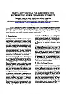
5 UML CLASS DIAGRAMS - REVISITED First of all let us have a closer look at the concepts of object oriented programming languages, namely the notions of object and class and adapt it afterwards to agent based systems. 5.1 Basics In object oriented programming languages an object consists of a set of instance variables, also called attributes or fields, and its methods. Creating an object its object identity is determined. Instance variables are variables holding special values, depending on the programming languages these fields can be typed. Methods are operations, functions or procedures, which can act on the instance variables and other objects. The values of the fields can be either pre-defined basic data types or references to other objects. A class describes a set of concrete objects, namely the instances of this class, with the same structure, i.e. same instance variables, and same behavior, i.e. same methods. There exists a standard method 'new', to create new instances of a class. A class definition consists of the declaration of the fields and the method implementations. It consists of a specification or an interface part as well as of an implementation part. The specification part describes, which methods with which functionality are supported by the class, but not how the operation is realized. The implementation part defines the implementation / realization of the methods and is usually not visible to the user of the method. The access rights define which methods are visible to the user and which one are not. In most programming languages classes define also types, i.e. each class definition defines a type of the same name. Some programming languages allow in class definitions also the definition of class variables, which are shared by all classes, in contrast to instance variables belonging to a single object. I.e. each instance of a class has its own storage for its instance variables, in contrast to class variables which share the same storage. Class variables are often used as a substitute for global variables. Beyond class variables, there are often used class methods which can be called independently of a created object and are used as global procedures. 5.2 Relating Objects to Agents Figure 8 illustrates our own view on the relationship between an agent and an object.
a ttr ib u te agent head ( g o a ls , a c tu a l s ta t e ,...)
a ttr ib u te a ttr ib u te
a c tio n
m e th o d
CA
a c tio n
m e th o d
CA
a c tio n
m e th o d
o b je c t
CA
Agent
Figure 8. object vs. agent We have autonomy, pro- and re-activity, the communication is based on speech act theory (communicative act, CA for short), the internal state is more than only fields with imperative data types, and additional features. All these concepts have to be supported by a class diagram for agents. In the agent oriented programming paradigm we have to distinguish between an agent class defining on the one side the type of an individual agent and being on the other side a blue print for individual agents, and individual agents. I.e. an (individual) agent is an instance of an agent class. Therefore we specify the schema of an agent class which is then used in programs as instantiated agents. An agent can be divided into the communicator - responsible for the physical connection, head dealing with goals, states, etc. of an agent, and body - performing the actions of the agent. For the internal view of an agent we have to specify the agent's head and body. The aim of the specification of the agent's internal behavior is to provide possibilities do define e.g. BDI semantics or permanent and actual goals as well as Java agents. Especially the semantics of the communicative acts and the reaction of an agent to some incoming messages have to be taken into consideration, this can be done either by the designer or the agent using e.g. BDI semantics. We allow the definition of a procedural as well as a declarative process description, the specification can e.g. be done using activity diagrams or the UML process specification language. The reaction to events and pro-active behavior can be defined either by pro-active actions or agent head automata for pro-active behavior. Not only methods can be defined for an agent which are only visible to the agent itself, but actions which can be accessed by other agents. But in contrast to object orientation the agent decides itself whether some action is performed or not. Abstract actions are characterized with pre-conditions, effects and invariants. Moreover the usual object oriented techniques have to be applied to agent technology, supporting efficient and structured program development, like inheritance, abstract agent types and agent interfaces, and generic agent types. Single, multi, and dynamic inheritance can be applied for states, actions, methods, and message handling. Associations are usable to describe e.g. agent A uses the services of agent B to perform a task (e.g. client, server), with some cardinality and roles. Aggregation and composition show e.g. car park service and car park monitoring can be part of an car park agent. The components can either be agent classes or usual object oriented classes. Several times we have argued that agent and objects are completely different paradigms. Therefore we have to distinguish in our specifications between agents and objects. Especially an agent can be build using some
object as part of its internal state. Therefore different notations between agents and objects have to be used either directly or using stereotypes. Relating classes in the sense of objects to agent technology raises the question what the term class means in the context of agents. Our answer is that in the same sense in which a class in the context of object oriented programming is a blueprint for objects, in our context an agent class has to be a blueprint for agents. This can be either an instance of an agent or a set of agents satisfying some special role or behavior. UML distinguishes different specification levels, namely the conceptual, the specification and the implementation level. For the agent oriented point of view in the conceptual level an agent class corresponds to an agent role or agent classification, e.g. monitoring and route planning can be defined in different agent classes. E.g. we can have an individual traffic (IT) route planning (RP) agent and an IT Monitoring agent informing the user about some traffic jams. On the specification level or interface level an agent class is a blueprint for instances of agents, e.g. the monitoring and route planner are part of one agent class. But only the interfaces are described and not the implementation, i.e. the agent head automata (see below) describing the behavior of the agent according to incoming messages is missing. Only the internal states and the interface, i.e. the communicative acts supported by the agent, are defined. The implementational level or code level is the most detailed description of a system, showing how instances of agents are working together and how the implementation of a class of agents look like. On this level the agent head automata has to be defined, too.
5.3 Agent class diagrams In this section we show how usual UML class diagrams can used and extended in the framework of agent oriented programming development. We will use the following notation to distinguish between different kinds of agent classes and instances. A g e n tC la ss
A g e n tC la s s / ro le -1 , ro le -2 , ...
A g e n tIn sta n c e / ro le -1 , ro le -2 ,...: A g e n tC la ss
Figure 9. different kinds of agent classes The first one denotes some agent class, the second some agent class satisfying distinguished roles and the last one defines some agent instance satisfying distinguished roles. The roles can be neglected for agent instances. According to the statement given above - what has to be specified for agent classes - we specify agents by the agent class diagram shown in Figure 10.
agent-class-name / rolename1, rolename-2, ...
state-description actions
methods
capabilities, service description, supported protocols
[constraint] society-name
CA-1 / protocol
CA-1 / protocol
CA-2 / protocol
CA-2 / protocol
agent-headautomata-name
notunderstood
default
IT RPAgent
IT Monitoring Agent
for short, e.g. Figure 10. agent class diagram and its abbreviations The usual UML notation can also be used to define such an agent class, but for more readable reasons we have introduced the above notation. Using stereotypes for an agent class written as a class diagram can look as shown in Figure 11. For a detailed description of the Agent class descriptions and roles, we refer to Section 4.1. 5.4 State description The state description looks similar to a field description in class diagrams with the exception that we introduce a distinguished class wff for well formed formula for all kinds of logical descriptions of the state, independent of the underlying logic. With this extension we have the possibility to define as well e.g. BDI agents. Beyond the extension of the type for the fields, we allow in addition to the visibility attributes a persistency attribute which characterizes that the value of this attribute
is persistence. E.g. in our personal travel assistance example the user agent can have an instance variable storing the already planned and booked travels. This field is persistent (denoted by the stereotype ) if the user agent is stopped and re-started later in a new session of the agent. Optionally the fields can be initialized with some values. In the case of BDI semantics one can define four instance variables, e.g. named beliefs, desires, intentions and goals each of type wff. Describing the beliefs, desires, intentions and goals of a BDI agent. These fields can be initialized with the initial state of a BDI agent. The semantics states that the wff holds for the beliefs, desires, intentions and goals of the agent. agent-class-name / rolename1, rolename-2, ... [constraint] society-name
fields methods
capabilities, service description, supported protocols
for short
IT RPAgent
IT Monitoring Agent
methods
CA-1/protocol
CA-1/protocol
CA-2/protocol
CA-2/protocol
default
default
Figure 11. using UML class diagrams to specify agent behavior and its abbreviations
In a pure goal-oriented semantics two instance variables of type wff can be defined, named permanent-goals and actual-goals, holding the formula for the permanent and actual goals. Usual UML fields can be defined if we have to specify a plain object oriented agent, i.e. an agent which is implementation on top of e.g. a Java-based agent platform, as e.g. JADE. However in different design stages different kinds of agent can be appropriate, e.g. on the conceptual level one can specify some BDI agents which are then implemented by some Javabased agent platform, i.e. some refinement steps from BDI agents to Java agents are performed. 5.5 Actions Pro-active behavior can be defined in two different ways, namely using pro-active actions and agent head automata with a pro-active behavior. The latter one will be considered later. Thus two kinds of actions can be specified for an agent: pro-active actions (denoted by the stereotype ) are triggered by the agent itself, e.g. using timer, or a special state is reached. I.e. it is tested on state changes of the agent (e.g. timer, sensor input) if the pre-condition of the action evaluates to true. Re-active actions (denoted by the stereotype ) are triggered by another agent, i.e. receiving some message from another agent.
The description of an agent's actions consists of the action signature with visibility attribute, actionname and a list of parameters with its associated types. The semantics of an action is defined by pre-conditions, post-conditions, effects and invariants as in UML. 5.6 Methods Methods are defined like in UML, eventually with pre-conditions, post-conditions, effects and invariants. 5.7 Capabilities The capabilities of an agent can be defined either in an informal way or using class diagrams for e.g. FIPA-service descriptions 5.8 Sending and Receiving of Communicative Acts The main interface of an agent to its environment is the sending and receiving of communicative acts. By communicative act (CA) we subsume the type of the message as well as the other information, like sender, receiver or content like in FIPA-ACL messages. We assume that the information about communicative acts are represented by classes and objects. How ontologies and classes / objects are playing together is beyond this paper and are reason for future work. The incoming messages are drawn as C A -1 / p ro to c o l
as instance.
C A -1 / p ro to c o l
and the outgoing messages are drawn
. The received or sent communicative act can either be some class or some concrete
The notation CA-1 / protocol is used if the communicative act of class CA-1 is received in the context of an interaction protocol protocol. In the case of an instance of a communicative act the notation CA-1 / protocol is used. As alternative notation we write protocol[CA-1] and protocol[CA-1]. The context / protocol can be omitted if the communicative act is interpreted independent of some protocol. In order to re-act to all kinds of received communicative acts, we use a distinguished communicative act default, which matches every incoming communicative act. The not-understood CA is sent if an incoming CA cannot be interpreted. We distinguish between instances and classes, because of the following reasons: • An instance describes a concrete communicative act with fixed content or other fixed values. Thus if we have a concrete request, say "start auction for a special good", an instance of a communicative act would be used. • In order to allow a more flexible or generic description, say "start auction for any kind of good", of the interface of an agent classes are used for the communicative acts. 5.9 Matching of Communicative Acts A received communicative act has to be matched against the incoming communicative acts of an agent to trigger the corresponding behavior of the agent. The matching of the communicative acts depends on the ordering of them, namely the ordering from top to bottom, since more than one communicative act of the agent can match an incoming message. The simplest case is the default case, default matches everything and not-understood is the answer to messages not understood by an agent. Since we match on the one side instances of communicative acts, as well as classes of communicative acts, we have to define free variables within an instantiated communicative act. This is shown in Figure 12 (class diagram for
communicative acts where the instance variables have the type undef). Communicative acts are defined by classes without methods. Communicative Act
FIPA sender : undef receiver : undef ... content : undef
FIPA-Inform sender : undef receiver : undef ... content : undef
FIPA-InformHotelInfo sender : undef receiver : undef ... content : HotelInfo
Figure 12. instance hierarchy on communicative acts, being an instance of the corresponding class hierarchy. An input communicative act CA matches an incoming message CA', iff •
•
CA is a class, then •
CA' must be an instance of class CA or
•
CA' must be a subclass of class CA or a subclass of it.
CA is instance of some class, then •
CA' is instance of the same class as CA and
•
CA.field matches CA'.field for all fields field of the class CA, defined as •
CA.field matches CA'.field, if CA.field has the value undef.
•
CA.field matches CA'.field, if CA.field is equal to CA'.field with CA.field not equal to undef and the type of field is a basic type.
•
CA.field matches CA'.field, if CA.field is unequal to undef and the type of field is not a basic data type and CA.field are instance of the same class C and CA.field.cfield matches CA'.field.cfield for all fields cfield of class C.
In the case of a communicative act in the context of a protocol, protocol[CA] matches protocol'[CA'], if CA matches CA' and protocol' is equal to protocol. The analogous holds for outgoing messages, in this case the communicative act has to match the result communicative acts of the agent head automata.
5.10 Agent-Head-Automata The agent head automata defines the behavior of an agent's head. We had defined an agent consisting of an agent's communicator, head and body. The agent communicator is responsible for the physical communication of the agent. The main functionality of the agent is implemented in the agent body. This can be e.g. an existing legacy software which is coupled to the multi agent system using wrapper mechanisms. The agent's head is the "switch-gear" of the agent. Its behavior has to be specified with the agent head automata. Especially this automata relates the incoming messages with the internal state, actions and methods and the outgoing messages, called the re-active behavior of the agent. Moreover it defines the pro-active behavior of an agent, i.e. it automatically triggers different actions, methods and state-changes depending on the internal state of the agent. An example of a pro-active behavior is to do some action at a specific time, e.g. an agent migrates at pre-defined times from one machine to another one, or it is the result of some request-when communicative act. UML supports for the definition of dynamic behavior four kinds of diagrams, namely sequence diagrams, collaboration diagrams on the object level, state and activity diagrams for other purposes. Sequence diagrams and collaboration diagrams are suitable for the definition of an agent's head behavior, since it is a object / agent instance focused diagram. So it can easily be used to define the concrete behavior, namely based on the actions, methods and state changes. It is up to the preferences of the designer to apply one of these diagrams. The state and the activity diagram is more suitable for a more abstract specification of the behavior of an agent's head. Again it is up to the designer to use one of these two diagrams. Let us first of all have a closer look at the re-active behavior. We have to specify how the agent reacts to incoming. The notation we use for this purpose are extended state automata (see Figure 12). In contrast to standard state automata the CA-notation of the class diagram is used to trigger an automata (initial states) and the final states match with the outgoing communicative acts. agent head automata
CA-1 / protocol
State
.......
CA-1 / protocol
state
Figure 13. extended state automata Pro-active behavior is not triggered by incoming messages, but depends on the validity of constraints or conditions. I.e. in the state automata the initial state(s) are marked with some conditions.
6 EVALUATION AND CONCLUSION The artifacts for agent-oriented analysis and design were developed and evaluated in the German research project MOTIV-PTA (Personal Travel Assistant) [5], aiming at providing an agent-based infrastructure for travel assistance in Germany (see http://www.motiv.de). MOTIV-PTA run from 1996 to 2000. It is a large-scale project involving approx. ten industrial partners, including Siemens, BMW, IBM, DaimlerChrysler, debis, Opel, Bosch, and VW. The core of MOTIV-PTA is a multiagent system to wrap a variety of information services, ranging from multimodal route planning, traffic control information, parking space allocation, hotel reservation, ticket booking and purchasing, meeting scheduling, and entertainment. From the end user's perspective, the goal is to provide a personal travel assistant, i.e., a software agent that uses information about the users' schedule and preferences in order to assist them in travel, including preparation as well as on-trip support. This requires providing ubiquitous access to assistant functions for the user, in the office, at home, and while on the trip, using PCs, notebooks, information terminals, PDAs, and mobile phones. From developing PTA (and other projects with corporate partners within Siemens) the requirements for artifacts to support the analysis and design became clear, and the material described in this paper has been developed incrementally, driven by these requirements. So far no empirical tests have been carried out to evaluate the benefits of the AGENT UML framework. However, from our project experience so far, we see two concrete advantages of these extensions: Firstly, they make it easier for users who are familiar with object-oriented software development but new to developing agent systems to understand what multiagent systems are about, and to understand the principles of looking at a system as a society of agents rather than a distributed collection of objects. Secondly, our estimate is that the time spent for design can be reduced by a minor amount, which grows with the number of agent-based projects. However, we expect that as soon as components are provided to support the implementation based on AGENT UML specifications, this will widely enhance the benefit. Areas of future research include aspects such as • • • •
description of mobility, planning, learning, scenarios, agent societies, ontologies and knowledge development of patterns and frameworks support for different agent communication languages and content languages development of plug-ins for CASE-tools
At the moment we plan to extend the presented framework towards inclusion of these topics.
References [1] B. Bauer. Extending UML for the Specification of Interaction Protocols. submission for the 6th Call for Proposal of FIPA and revised version part of FIPA 99, 1999. [2] B. Bauer: UML Class Diagrams Revisited in the Context of Agent-Based Systems, submitted to AOSE 2001, Montreal, 2001 [3] B. Bauer, J. Odell, H. v. D. Paranuk: AUML - First Steps, Proceedings of SCI/ISAS 2000, Orlando, FL, 2000. [4] B. Bauer, J.P. Müller, J. Odell: An Extension of UML by Protocols for Multiagent Interaction, Proceeding, Fourth International Conference on MultiAgent Systems, ICMAS 2000, Boston, IEEE Computer Society, 2000. [5] B. Bauer, M. Berger: Agent-Based Personal Travel Assistance, accepted for MAMA 2000, 2000. [6] F. M. T. Brazier, C. M. Jonkers, and J. Treur. Principles of Compositional Multi-Agent System Development. Proceedings 15th IFIP World Computer Congress, WCC'98, Conference on Information Technology and Knowledge Systems, IT&KNOWS'98, pages 347-360, Chapman and Hall, 1998.
[7] J. Bryson, and B. McGonigle. Intelligent Agents IV: Agent Theories, Architectures, and Languages. Proceedings ATAL 98, ed., Springer, 1998 [8] B. Burmeister, A. Haddadi, and K. Sundermeyer. Generic, Configurable, Cooperation Protocols for Multi-Agent Systems. Proceedings Fifth European Workshop on Modelling Autonomous Agents in a Multi-Agent World, MAAMAW'93, pages 157-171, Springer, 1993. [9] B. Burmeister. Models and Methodology for Agent-Oriented Analysis and Design. ed., 1996. [10] http://www.fipa.org [11] E. Gamma, R. Helm, R. Johnson, and J. Vlissides. Design Patterns. Addison-Wesley, 1997. [12] F. J. Garijo, and M. Boman. Multi-Agent System Engineering. Proceedings of MAAMAW'99. Springer, ed., 1999. [13] D. E. Herlea, C. M. Jonker, J. Treur, and N. J. E. Wijngaards. Specification of Behavioural Requirements within Compositional Multi-Agent System Design. Proceedings of Ninth European Workshop on Modelling Autonomous Agents in a Multi-Agent World, pages 8-27, Springer, 1999. [14] C. A. Iglesias, M. Garijo, and J. C. González. A Survey of Agent-Oriented Methodologies. Proceedings of Fifth International Workshop on Agent Theories, Architectures, and Languages, pages 185-198, University Pierre et Marie Curie, 1998. [15] N. R. Jennings, K. Sycara, and M.J.Wooldridge. A Roadmap of Agent Research and Development. Journal of Autonomous Agents and Multi-Agent Systems. 1(1), pages 7-36. July 1998. [16] C. M. Jonker, and J. Treur. Compositional Verification of Multi-Agent Systems: a Formal Analysis of Pro-activeness and Reactiveness. Proceedings of International Workshop on Compositionality (COMPOS'97), Springer, 1997. [17] D. Kinny, and M. Georgeff. Modelling and Design of Multi-Agent Systems. Intelligent Agents III, Springer, 1996. [18] D. Kinny, M. Georgeff, and A. Rao. A Methodology and Modelling Technique for Systems of BDI Agents. 7th European Workshop on Modelling Autonomous Agents in a Multi-Agent World (MAAMAW'96)., pages 56-71. Springer, 1996. [19] J. P. Müller. The Design of Autonomous Agents : A Layered Approach, volume 1177 of Lecture Notes in Artificial Intelligence. Springer-Verlag, Heidelberg, 1997. [20] J. Odell and M. Fowler. Advanced object-oriented analysis and design using UML. SIGS Books / Cambridge University Press, 1998. [21] J. Odell. Agent Technology, green paper, produced by the OMG Agent Working Group, ed., 1999. [22] J. Odell, H. v. D. Paranuk, B. Bauer: Representing Agent Interaction Protocols in UML, Proceedings of the Workshop on Agents in Industry, Autonomous Agents 2000, 2000 [23] H. V. D. Parunak. Visualizing Agent Conversations: Using Enhanced Dooley Graphs for Agent Design and Analysis. Proceedings of Second International Conference on Multi-Agent Systems, pages 275-282, 1996. [24] H. V. D. Parunak, and J. Odell. Engineering Artifacts for Multi-Agent Systems, ERIM CEC, 1999. [26] M. Wooldridge, N. R. Jennings and D. Kinny. The Gaia Methodology for Agent-Oriented Analysis and Design. International Journal of Autonomous Agents and Multi-Agent Systems, 3, 2000.