3 Dipartimento di Sistemi e Informatica, Universit`a di Firenze. 4 Istituto di Scienze e ... Application areas of AGILE include E-Business, Telecommunications, Wireless. Applications ...... S. Kuske, M. Gogolla, R. Kollmann, and H.J. Kreowski.
AGILE: Software Architecture for Mobility?
??
L. Andrade6 , P. Baldan8 , H. Baumeister1 , R. Bruni2 , A. Corradini2, R. De Nicola3 , J. L. Fiadeiro6 , F. Gadducci2 , S. Gnesi4 , P. Hoffman7 , N. Koch1 , P. Kosiuczenko1, A. Lapadula3 , D. Latella4 , A. Lopes5 , M. Loreti3 , M. Massink4 , F. Mazzanti4 , U. Montanari2 , C. Oliveira5 , R. Pugliese3 , A. Tarlecki7, M. Wermelinger5 , M. Wirsing1 , and A. Zawlocki7 1
4
Institut f¨ ur Informatik, Ludwig-Maximilians-Universit¨ at M¨ unchen 2 Dipartimento di Informatica, Universit` a di Pisa 3 Dipartimento di Sistemi e Informatica, Universit` a di Firenze Istituto di Scienze e Tecnologie dell’Informazione “A. Faedo” CNR Pisa 5 Faculdade de Ciˆencias da Universidade de Lisboa 6 ATX Software SA 7 Institute of Informatics, Warsaw University 8 Dipartimento di Informatica, Universit` a di Venezia
Abstract. Architecture-based approaches have been promoted as a means of controlling the complexity of system construction and evolution, in particular for providing systems with the agility required to operate in turbulent environments and to adapt very quickly to changes in the enterprise world. Recent technological advances in communication and distribution have made mobility an additional factor of complexity, one for which current architectural concepts and techniques can be hardly used. The AGILE project is developing an architectural approach in which mobility aspects can be modelled explicitly and mapped on the distribution and communication topology made available at physical levels. The whole approach is developed over a uniform mathematical framework based on graph-oriented techniques that support sound methodological principles, formal analysis, and refinement. This paper describes the AGILE project and some of the results gained during the first project year.
1
Introduction
Architecture-based approaches have been promoted as a means of controlling the complexity of system construction and evolution, in particular for providing systems with the agility that is required to operate in turbulent environments and to adapt very quickly to new business requirements, new design technologies, or even to changes in the enterprise world which, like mergers and acquisitions, ?
??
This research has been partially sponsored by the EC 5th Framework project AGILE (IST-2001-32747) (www.pst.informatik.uni-muenchen.de/projekte/agile). Appeared in Recent Trends in Algebraic Develeopment Techniques—16th International Workshop, WADT 2002, Frauenchiemsee, Germany. Vol. 2755 of LNCS. c Springer Verlag, 2003.
1
require new levels of openness and interoperability. However, the architectural approach offers only a “logical” view of change; it does not take into account the properties of the “physical” distribution topology of locations and communication links. It relies on the fact that the individual components can perform the computations that are required to ensure the functionalities specified for their services at the locations in which they are placed, and that the coordination mechanisms put in place through connectors can be made effective across the “wires” that link components in the underlying communication network. Whereas the mobility of computations is a problem that we are becoming to know how to address in the field of “Global Computation”, the effects of mobility on coordination are only now being recognised as an additional factor of complexity, one for which current architectural concepts and techniques are not prepared for. As components move across a network, the properties of the wires through which their coordination has to take place change as well, which might make the connectors in place ineffective and require that they be replaced with ones that are compatible with the new topology of distribution. In addition, updates on the communication infrastructure will lead, quite likely, to revisions of the coordination mechanisms in place, for instance to optimise performance. The AGILE project aims to contribute to the engineering of Global Computation and Coordination Systems. It is funded by EU initiative on “Global Computing”. The partners of the AGILE project are Ludwig-Maximilians-Universit¨ at M¨ unchen, Universit` a di Pisa, Universit` a di Firenze, Istituto di Scienze e Tecnologie dell’Informazione “A. Faedo” CNR Pisa, ATX Software SA, Faculdade de Ciˆencias da Universidade de Lisboa, and more recently the University of Warsaw and the University of Leicester. The objective of AGILE is to develop an architectural approach in which mobility aspects can be modelled explicitly as part of the application domain and mapped to the distribution and communication topology made available at physical levels. The whole approach is developed over a uniform mathematical framework based on graph-oriented techniques that support sound methodological principles, formal analysis, and refinement across levels of development. Application areas of AGILE include E-Business, Telecommunications, Wireless Applications, Traffic Control Systems and decision support systems which need to collect global information. More precisely, AGILE pursues the following three main research topics: – The development of primitives for explicitly addressing mobility within architectural models. This work is based on CommUnity and its categorical framework [17, 16] supporting software architectures on the basis of the separation between “computation” and “coordination” with an additional dimension for “distribution”. Consequently, primitives for the third dimension of “mobility”, are developed with which the distribution topology can be explicitly modelled and refined across different levels of abstraction. – The definition of algebraic models for the underlying evolution processes, relating the reconfiguration of the coordination structure and the mobility of components across the distribution topology. This work is based on graph 2
transformation techniques [7] and Tile Logic [18], and is also the basis for logical analysis of evolution properties as well as for tools for animation and early prototyping. – The development of an extension of UML for mobility that makes the architectural primitives available to practitioners, together with tools for supporting animation and early prototyping. The following main aspects are pursued in all three research topics: – analysis techniques for supporting compositional verification of properties addressing evolution of computation, coordination and distribution, and – refinement techniques for relating logical modelling levels with the distribution and communication topology available at physical levels In this paper we give an introduction to the approach of the AGILE project and present some of the results gained during the first project year. In particular, we present extensions of three well-known formalisms to mobility: extensions of CommUnity, of UML, and of Graph Transformation Systems. We also introduce an extension of Klaim, an experimental kernel programming language specifically designed to model and to program distributed concurrent applications with code mobility. In the developed extension of CommUnity, primitives were added to CommUnity that support the design of components that can perform computations in different locations and be interconnected to other components over a distributed and mobile network. Patterns of distribution and mobility of components (or groups of components) can be explicitly represented in architectures through a primitive called distribution connector. These patterns include coordination patterns that are location-dependent or even involve the management of the location of the coordinated parties. The semantics of the architectural aspects of this extension were developed over the categorical formalisation already adopted for CommUnity. The extensions of UML cover class diagrams, sequence diagrams, and activity diagrams. The idea for all of these extensions is similar to the idea of ambients or Maude, in that a mobile object can migrate from one host to another and it can be a host for other mobile objects. It may interact with other objects. Like a place, a mobile object can host other mobile objects, and it can locally communicate and receive messages from objects at other places. Objects can be arbitrarily nested, generalising the limited place-agent nesting of most agent and place languages. Graph Transformations Systems are used to give an operational semantics to the UML extensions. Object diagrams and the actions of activity diagrams are represented using Typed Hyperedge Replacement Systems. Each action of an activity diagram is modelled by a unique graph transformation rule. We can show that under suitable assumptions a set of graph transformation rules implements correctly the dependencies in an activity diagram. In case stronger synchronisation is necessary, we use a specialisation of the tile model: Synchronised Typed Hyperedge Replacement Systems. 3
As for Klaim, although designed for dealing with mobility of processes located over different sites of local area networks, it lacked specific primitives for properly handling open systems, namely systems with dynamically evolving structures where new nodes can get connected or existing nodes can disconnect. In the paper we present OpenKlaim, an extension of Klaim with constructs for explicitly modeling connectivity between network nodes and for handling changes in the network topology. The paper is organised as follows. The next section introduces the airport case study, which serves as a running example for the material in the following sections. Section 3 presents our UML extensions for modelling mobile systems. Next, in Sect. 4 we present our research on the structural aspects of the architectural approach. The starting point for this research are CommUnity (Sect. 4.1) and Klaim (Sect. 4.2). Section 5 presents the way graph transformation and its synchronised version (which is a specific instance of the Tile Mode) can be used for the specification of a fragment of the airport case study. Finally, in Sect. 6 a conclusion and an outlook to future work is presented.
2
The Airport Case Study
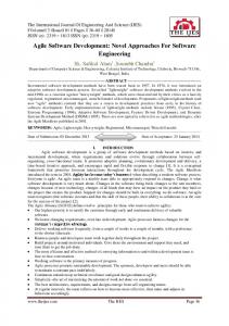
As an example of mobile objects we consider planes landing and taking off from airports. These planes transport other mobile objects: passengers. In a simplified version of this scenario, departing passengers check in and board the plane. After the plane has arrived at the destination airport, passengers deplane, and claim their luggage. We consider also actions performed by the passengers during the flight, like the consumption of a meal, or making and publishing pictures. Figure 1 shows these requirements as a UML use case diagram. A use case diagram consists of use cases and actors. The identified actors are the Airport, the Passenger and the Plane. The actor Airport starts the use cases Departure and Arrival, which allow passengers to check in and to deplane, respectively, and allow planes to take off and land, respectively (included use cases TakingOff and Landing). Planes control the use case Flying. The flow of events of a use case can either be detailed textually or graphically using UML activity diagrams or UML sequence diagrams. The objects involved and their classes are described by class diagrams. Parts of this case study serve as running example for the modelling techniques presented in the following sections.
3
UML for Global Computation
UML is extended using the extension mechanisms provided by the UML itself, i.e. stereotypes, tagged values and OCL constrains as well as by improvements in the visual representation used in activity and sequence diagrams. The objective of this research is to develop an extension of the UML to support mobile and distributed system design. This includes linguistic extensions 4
Take off
Departure
Check in
Airport
Passenger
Arrival
Landing
Plane
Flying
Fig. 1. Use Case diagram
of the UML diagrammatic notations using the extension mechanisms provided by the UML itself, i.e. stereotypes, tagged values, and OCL constrains, as well as introducing new visual representations. Further, the objective includes extensions of the Unified Process and a prototype for simulating and analysing the dynamic behaviour of designs of mobile and distributed systems. In this section, we give a UML (Unified Modeling Language) [34] specification of the flight. The specification consists of use case diagrams, class diagrams, activity diagrams and sequence diagrams. In the following we show only a part of the solution; a more comprehensive solution can be found in [3, 27]. 3.1
Class Diagrams
We model the simplified airport problem domain using UML class diagrams. We identify the following classes: Airport, Plane, Flight, Passenger and Country, where: – – – –
Airport is an origin or destination location. Flight is the trip that happens along a particular route on a particular day. Plane is the machine that operates a flight. Passenger is a person who is waiting for boarding a plane at an airport, is on a plane or has just arrived at the airport. – Country is a place where an airport is located.
In our extension of class diagrams for mobility, we distinguish between objects and locations which are movable and which are not (cf. [3]). Movable objects are denoted with the UML stereotype �mobile�, and objects which can serve as locations are indicated with the stereotype �location�. Movable objects and locations are required to have a unique attribute atLoc whose value is the location they are at. We require that the relation given by the atLoc attribute is acyclic. Note that this implies that locations form a hierarchy. 5
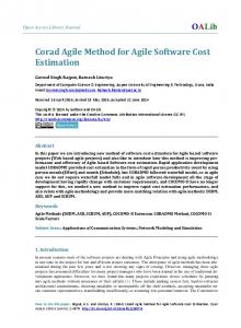
We can only move objects and locations that are movable. In our example, Passenger and Plane are mobile objects. In addition, Plane has a location role, the same as Airport. The problem domain is visualised as a UML class diagram as it is shown in Fig. 2. Note that OCL constraints [34] can be attached to modelling elements to express semantic conditions. Country name 1 * has Airport
TakeOff is only possible when all passengers have boarded
name origin 1
*
1 destination
* Plane type operate numberOfSeats * land() takeOff()
Luggage
* Flight
*
number date boardingTime gate
1
1 *
*
*
1 Passenger name eat() board() deplane()
1
Ticket
1 1
Fig. 2. Class diagram of the airport example
3.2
Activity Diagrams
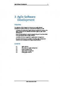
In this section we introduce two variants of activity diagrams for modelling mobility. These diagrams were introduced in [3]. The first variant is responsibility centered and uses swimlanes to model who is responsible for an action. The second is location centered and uses the notation of composite objects to visualise the hierarchy of locations. A typical activity of mobile objects is the change of location, i.e., the change of the atLoc attribute. An object can move from one location to another. In our UML extension, we distinguish these activities by representing them as a stereotyped activity that we call �move�. (cf. 4). Not included in the example, but not less important is the stereotyped activity called �clone� that first clones the object to be moved afterwards. Figure 3 shows the activity diagram corresponding to the Departure use case. Note that the fact that the plane can only take off if the passenger boarded and the luggage is loaded is expressed by the use of joins in the UML activity diagram. 6
Passenger
Munich Airport
Plane
checks in
boards
loads luggage
takesOff
Fig. 3. Activity diagram of the departure scenario
Compare this with the CommUnity approach presented in Sec. 4.1. Note that partitions marked with actor’s names are defined to organise responsibilities for these activities. Such an activity diagram with partitions gives a responsibilitycentred view of the flow of events. Once the objects are identified, the activity diagrams can be enhanced with object flows, showing relationships among successive loci of control within the interaction. Figure 4 shows such an enhanced activity diagram. The objects are attached to the diagram at the point in the computation at which they are suitable as an input or produced as an output. In our example, the in-going objects to an activity are very often the same as the outgoing. The corresponding state of the objects is specified in the square brackets (cf. objects Plane and Passenger in Fig. 4). This is what we call responsibility-centred view; the responsibilities are given by swimlanes and the locations are represented indirectly by object states. We present here also another kind of view, the so called location-centred view, with the goal to visualise a location directly by object box containment: states of objects are not longer needed to represent locations. We eliminate the swimlanes and we place the activities inside the locations. This UML extension gives a direct presentation of the topology of locations. Figure 5 shows the Departure and the Flight scenario. 3.3
Sequence Diagrams
In this subsection we consider again a flight from Munich to Lisbon. We specify the flight from two different perspectives. The first perspective is the perspective 7
Passenger
Munich Airport
Plane
checks in :Passenger [at source airport] « move » boards
loads luggage
:Plane [at source airport]
:Passenger [at the plane] «move » takesOff :Plane [in the air]
Fig. 4. Activity diagram departure scenario: Responsibility centered view
of an observer in Munich. The second perspective refines the first one adding several details. We use here the extension of UML sequence diagrams proposed in [27] for modelling mobile objects. The behaviour of mobile objects is modelled by a generalised version of lifelines which allows us to represent directly the topology of locations within a sequence diagram. For different kinds of actions like creating, entering or leaving a mobile object stereotyped messages are used. This notation provides also a zoom-out, zoom-in facility allowing us to abstract from specification details. Figure 6 shows a simple story of a passenger x who boards an airplane in Munich airport, flies to Lisbon and publishes a picture in a WAN. The domain model of this sequence diagram is based on the class diagram of Fig. 2 and uses additionally the class Network. The story is described from the perspective of an observer on the German side. The person x together with other passengers enters the airport and then boards the airplane A7. The airplane flies to Lisbon (the flight number is 99), but the only thing the observer can see is that the airplane is airborne, but not what happens inside the airplane nor further details of this flight. The next event which the observer is able to notice is the appearance of a picture in the WAN. To model several passengers (i.e. objects of class Passenger), we use the UML multi-object notation, which allows us to present in a compact way several passengers playing the same role. Person x is distinguished using the composition relationship. The observer does not care about the order in which the passengers board or leave the plain and what they do during the flight. We abstracted here also from the architecture of WAN and the person’s position. This simple view shows some of the barriers person x has to cross while flying from Munich to Lisbon. In the view presented in Fig 7, 8
Munich:Airport
checks in :Passenger «move » boards
deliver luggage
:Plane :Passenger :Air :Plane « move »
:Passenger
takesOff eats
flies
Fig. 5. Activity diagram: Location centered view
we show much more details. We show political boundaries which regulate the movement of people and devices, like airplanes, computers and so on. Within those boundaries, there are other boundaries like those protecting airports and single airplanes against intruders. Only people with appropriate passports and tickets may cross those boundaries. Therefore, in our model we make explicit those boundaries and moving across them. The airplane A7 is a very active mobile computing environment, full of people who are talking, working with their laptops, calling their families, making pictures or connecting to Web via phones/modems provided in the airplane. We can see here, what happens inside the airplane during the flight; the jump arrow contains the action box of the airplane A7. Passenger x makes pictures with his digital camera, the pictures are send then to the WAN. As usual, a digital camera does not allow him to send pictures directly to WAN. It is also forbidden to use mobile phones during the flight. Therefore the passenger safes the pictures to his notebook nb, logs into the onboard network and then transmits the pictures to WAN via the onboard network. We abstract here from the structure of the WAN network (indicated by dashed line). Let us point out that the sending of the picture by passenger x is not temporally related to crossing any border like those of Germany, or Munich and so on. The only thing we can say is that it happens between the start of the 9
��� ������ � �� � 01�� �2 3 4 ��* # � � + , � %.-&/
#�$&%�'�'!(
���� ��� ��
�� � )
� � � ���! "�"
�����
Fig. 6. Sequence diagram with mobility M�7 8�9 :�;. a�:�;�C b c _ O� @�] F @ P ^ H ZI`
F�GIHIJ�J!K
5�6�7 8�9 :�;. L
B C D�E�9 ; N O P Q.R!S T T
WYX L
?1@�A \
U�U V V
Z�U [ V
F�GIHIJ�JIK
\ d
Fig. 7. Sequence diagram with mobility: zoom in
airplane and its landing. Finally, all the passengers leave the airplane and the airport. The passenger can see that the airplane is boarded by new passengers. 3.4
Statechart diagrams
In this section we show the use UML statecharts for the design and the specification of the dynamic behaviour of the airport system. A statechart diagram is defined for each class of the model, providing a complete operational description of the behaviour of all the objects of the class. The full system is then represented by a set of class objects. The UML semantics [34, 37, 31, 38] associates to each active object a state machine, and the possible system behaviours are defined by the possible evolutions of these communicating state machines. All the possible system evolutions can be formally represented as a bi-labelled transition system in which the states represent the various system configurations and the edges the possible evolutions of a system configuration. The topology of the system 10
is modelled by an atLoc attribute, associated to each class, which represents its locality. Mobility is realized by all the operations which update the atLoc attribute of an object (the �move� operations). The verification of the system is done with a prototypal “on-the-fly” model checker (UMC) (cf. [20]) for UML statecharts. On-the-fly verification means intuitively that, when the model checker has to verify the validity of a certain temporal logic formula on one state, it tries to give an answer by observing the internal state properties (e.g. the values of its attributes) and than by checking recursively the validity of the necessary subformulas on the necessary next states. In this way (depending on the formula) only a fragment of the overall state space might need to be generated and analysed to be able to produce the correct result (cf. [5, 14]). The logic supported by UMC, µACTL+ (cf. [20]) is an extension of the temporal logic µACTL, (cf. [13]) which has the full power of µ-calculus (cf. [28]). This logic allows both to specify the basic properties that a state should satisfy, and to combine these basic predicates with advanced logic or temporal operators. More precisely the syntax of µACTL+ is given by the following syntax where the χ formulae represent evolution predicates over, signal events sent to a target object (here square parenthesis are used to denote optional parts): χ ::= true | [target.]event[(args)] | ¬χ | χ ∧ χ
φ ::= true | φ ∧ φ | ¬φ | assert(VAR = value) | EXτ φ | EXχφ |EF φ | µY.φ(Y ) | Y
where Y ranges over a set of variables, state formulae are ranged over by φ, EXχ is the indexed existential next operator and EF is the eventually operator. Several useful derived modalities can be defined, starting from the basic ones. In particular, we will write AGφ for ¬EF ¬φ, and νY.φ(Y ) for ¬µY.¬φ(¬Y ); ν is called the maximal fixpoint operator. The formal semantic of µACTL+ is given over bi-labelled transition systems. Informally, a formula is true on an LTS, if the sequence of actions of the LTS verifies what the formula states. We hence say that the basic predicate assert(VAR = value) is true if and only if in the current configuration the attribute VAR has value equal to value. The formula EXχφ holds if there is a successor of the current configuration which is reachable with an action satisfying χ and in which the formula φ holds. The formula AGφ, illustrates the use of the ”forall” temporal operator and holds if and only if the formula φ holds in all the configurations reachable from the current state. Following the above syntax we will write using µACTL+ formulae such as: EX {Chart.my event} true that means: in the current configuration the system can perform an evolution in which a state machine sends the signal myevent to the state machine Chart. Or the formula: AG ((EX {my event} true) → assert(object.attribute = v)) meaning that the signal myevent can be sent, only when the object attribute has value v. 11
∗
Coming back to the airport example, let us consider an extremely simplified version of the system composed of two airports, two passengers (one at each airport), and one plane. The plane is supposed to carry exactly one passenger and flies (if it has passengers) between the two airports. Departing passengers try to check in at the airport and than board the plane. We contemplate only one observable action performed by the passengers during the flight, namely the consumption of a meal. The complete dynamic behaviour of the objects of classes Passenger, Airport and Plane, is shown in Fig. 8 and Fig. 9, in the form of statecharts diagrams.
created
landing_request(P) / P.landing_delayed
- [ MyPlane = null ]
- [MyPlane /= null]
checkin(D,T) / T.checkin_closed
HANDLING CHECKIN
HANDLING LANDING
checkin(D,T) [D=MyLink ] / T.checkin_ok; MyPlane.allow_boarding(T,D)
landing_request(P) / P.landing_delayed
landing_request(P) / P.allow_landing
checkin(D,T) / T.checkin_closed
landing_request(P) / P.landing_delayed
HANDLING BOARDING
HANDLING ARRIVALS
landing_done(P)/ MyPlane := P;
boarding_done / MyPlane.allow_takeoff landing_request(P) / P.landing_delayed
checkin(D,T) / T.checkin_closed
checkin(D,T) / T.checkin_closed HANDLING TAKEOFF takeoff_done / MyPlane := null;
Fig. 8. Airport statemachine
The initial deployment of the system is defined by the following declarations object Airport1 Airport2 Traveler1 Traveler2 Plane1
class Airport Airport Passenger Passenger Plane
initial values for attributes MyLink ⇒ Airport2, MyPlane ⇒ Plane1 MyLink ⇒ Airport1 atLoc ⇒ Airport1, Destination ⇒ Airport2 atLoc ⇒ Airport2, Destination ⇒ Airport1 atLoc ⇒ Airport1 12
PASSENGER STATECHART
PLANE STATECHART
STARTING
BOARDING
-/ atLoc.checkin(Destination,Self)
allow_boarding(T,D) / T1 := T; MyDest:=D; T1.onboard(Self); atLoc.boarding_done
TRYING CHECKIN checkin_closed / atLoc.checkin(Destination,Self)
checkin_ok
LEAVING allow_takeoff / atLoc.takeoff_done; atLoc := null; T1.take_tray
BOARDING onboard (Plane)/ atLoc := Plane
FLYING
EATING take_tray / OUT. eating (Self); atLoc.takeback_tray
takeback_tray / MyDest.landing_request(Self)
DEPLANING deboard / atLoc := Destination
LANDING landing_delayed / MyDest.landing_request(Self);
allow_landing / MyDest.landing_done(Self); atLoc := MyDest; T1.deboard
Fig. 9. Plane and passenger statemachines
An example of property which can be verified over this system is the following: It is always true that Traveler1 can eat only while he/she is flying on Plane1. This property can be written in µACTL+ as: AG ((EX {eating(Traveler1)} true) → (assert (Traveler1.atLoc = Plane1) & assert(Plane1.atLoc = null))) We wish to point out that that the development activity of UMC is still in progress and we have reported here some preliminary results on its application to the airport case study. Indeed several aspects of UML statcharts are not currently supported (e.g. the execution of “synchronous call” operations, the use of “deferred events”, the use of “history states”), and the logic itself needs to be better investigated, (e.g. its relation with localities). Work in this direction is planned in the next future. 13
4
The structural aspects of the architectural approach
The goal of the research on architectures is to develop the structural aspects of the architectural approach to mobility, including semantic primitives, categorical semantics, refinement mechanisms, and a toolbox of connectors and operations, as well as modularisation and structuring facilities for the systems considered and their specifications. The starting point for this research are three complementary formalisms: the parallel program design language CommUnity [17] as a platform in which the separation between “computation” and “coordination” has been achieved; the language Klaim [11] as a programming language with appropriate coordination mechanisms that permit negotiating the cooperation activities of mobile components, services and resources; the specification language CASL [1] as a means for providing architectural specification and verification mechanisms. During the first year of the project, the grounds for the integration of distribution and mobility in architectures were set by designing and mathematically characterising basic extensions of CommUnity for distribution and mobility, by adding higher-order mechanisms to Klaim, and by enriching CASL with observational interpretation. In the following we will focus on the extensions to CommUnity by presenting a solution of the airport scenario. 4.1
CommUnity
CommUnity, introduced in [17], is a parallel program design language that is similar to Unity [6] in its computational model but adopts a different coordination model. More concretely, whereas, in Unity, the interaction between a program and its environment relies on the sharing of memory, CommUnity relies on the sharing (synchronisation) of actions and exchange of data through input and output channels. Furthermore, CommUnity requires interactions between components to be made explicit whereas, in Unity, these are defined implicitly by relying on the use of the same variables names in different programs. As a consequence, CommUnity takes to an extreme the separation between computation and coordination in the sense that the definition of the individual components of a system is completely separated from the interconnections through which these components interact, making it an ideal vehicle for investigating the envisaged integration of distribution and mobility in architectural models. In CommUnity the functionalities provided by a component are described in terms of a set of named actions and a set of channels. The actions offer services through computations performed over the data transmitted through the channels. Channels In a component design channels can be declared as input, output or private. Private channels model internal communication. Input channels are used for reading data from the environment of the component. The component has no control on the values that are made available in input channels. Moreover, reading a value from an input channel does not consume it: the value 14
remains available until the environment decides to replace it. Output and private channels are controlled locally by the component, i.e. the values that, at any given moment, are available on these channels cannot be modified by the environment. Output channels allow the environment to read data produced by the component. Private channels support internal activity that does not involve the environment in any way. Each channel is typed with the sort of values that it can transmit. Actions The named actions can be declared either as private or shared. Private actions represent internal computations in the sense that their execution is uniquely under the control of the component. Shared actions offer services to other components and represent possible interactions between the component and the environment, meaning that their execution is also under the control of the environment. The significance of naming actions will become obvious below; the idea is to provide points of rendezvous at which components can synchronise. Space of Mobility We adopt an explicit representation of the space within which mobility takes place, but we do not assume any fixed notion of space. This is achieved by considering that space is constituted by the set of possible values of a special data type Loc included in the fixed data type specification over which components are designed. The data sort Loc models the positions of the space in a way that is considered to be adequate for the particular application domain in which the system is or will be embedded. The only requirement that we make is for a special location ⊥ to be distinguished whose role will be discussed further below. In this way, CommUnity can remain independent of any specific notion of space and, hence, be used for designing systems with different kinds of mobility. For instance, in physical mobility, the space is, typically, the surface of the earth, represented through a set of GPS coordinates. In some kinds of logical mobility, space is formed by IP addresses. Other notions of space can be modelled, namely multidimensional spaces, allowing us to accommodate richer perspectives on mobility such as the ones that result from combinations of logical and physical mobility, or logical mobility with security concerns. Unit of Mobility In components that are location-aware, we make explicit how their constituents are mapped to the positions of the fixed space. Mobility is then associated with the change of positions. By constituents we mean channels, actions, or any group of these. This means that the unit of mobility — the smallest constituent of a system that is allowed to move — is fine-grained and different from the unit of execution. The constituents of a component are mapped to the positions of the space through location variables. These variables (locations, for short) can be regarded as references to the position of a group of constituents of a component that are permanently colocated. In a component design, locations can be declared as 15
input or output in the same way as channels but are all typed with sort Loc. Input locations are read from the environment and cannot be modified by the component. Hence, if l is an input location, the movement of any constituent located at l is under the control of the environment. Output locations can only be modified locally but can be read by the environment. Hence, if l is an output location, the movement of any constituent located at l is under the control of the component. Each local channel x of a design is associated with a location l. We make this assignment explicit by writing x@l. At every given state, the value of l indicates the position of the space where the values of x are made available. A modification in the value of l entails the movement of x as well as of the other channels and actions located there. Input channels are located at a special output location whose value is invariant and given by ⊥. The intuition is that this location variable is a non-commitment to any particular location. The idea is that input channels will be assigned a location when connected with a specific output channel of some other component of the system. Each action name g is associated with a set of locations including λ, meaning that the execution of action g is distributed over those locations. In other words, the execution of g consists of the synchronous execution of a guarded command in each of these locations.
Airport Example We consider a system that is required to control the check-in and boarding of passengers as well as the take-off of planes at airports. In the case of flights with stops, the system should also control the boarding and deplane of passengers during the intermediary stops. The design solution we shall adopt distributes the system over hosts at airports and planes and comprises mobile agents moving from host to host. Moreover, some of the hosts are themselves mobile. Flights, seats, airports and planes identifiers are modelled by data types.
ArpId % airports identifiers PlId % plane identifiers Flight % flight info src: Flight->ArpId %source of flights dest: Flight->ArpId %destination of flights next: ArpId*Flight->ArpId % next stop relationship of flights
We need a bi-dimensional space in order to model (1) the physical movement of planes and, consequently, the movement of the hosts they hold, and (2) code mobility. We define the data types Phy and Host to model these two dimensions. Locations consist of a physical location followed by a logical one — Phy.Host. For simplicity, we consider that airports and planes are associated with single hosts. 16
Host % logical dimension ahost:ArpId->Host phost:PlId-> Host Phy % physical dimension = ArpId+{air} Loc % locations = Phy.Host ph:Loc->Phy % 1st projection host:Loc->Host % 2nd projection
In the envisaged airport system, we may easily identify two component types — passenger and plane; both have a dynamic set of instances in the running system. Passengers have a seat in a given flight and are involved in activities such as check-in, boarding and exiting the plane. Planes operate flights, transporting luggage and passengers. They take off and land, possibly more than once.
design passenger is l inloc s@l: [0..2], seat@l: StId, fl@l: Flight prv checkin@l: [ s=0 → s:=1 ] do [] boards@l: [ s=1 → s:=2 ] [] leaves@l: [ s=2 → s:=1 ] design plane is l outloc fl@l: Flight, out s@l: [0..3], id@l: PlId, a@l:AirId prv load_lug@l: [ s=0 → s:=1 ] do [] takesoff@l: [ s=1 ∧ ph(l) dest(fl) → s:=2 || l:=air.host(l) || a:=next(a,fl)] [] lands@l: [ s=2 → s:=1 || l:=a.host(l) ] [] unload_lug@l: [ s=1 ∧ ph(l)=dest(fl) → s:=3 ]
Planes offer one output channel so that their behaviour can be coordinated according to the flights they operate. Whereas planes have output locations, passengers have input locations: this is because planes control their own mobility whereas passenger movement is determined by the environment, namely the planes that they board. It remains to define the coordination of the activities of planes and passengers at departure, namely the fact that a plane can take off only when all passengers that checked-in are on board. In CommUnity, the mechanisms through which coordination between system components is achieved can be completely externalised from the component programs and modelled explicitly as first-class citizens. The global property of the airport system just described can be achieved by interconnecting a plane and each of its passengers through a connector that ensures that the action takesoff of plane cannot precede the action boards of passenger. This coordination activity can be established by interconnecting plane and passenger to a scheduler: a program seq with two actions ac1 and ac2 that have to be executed in order. The required interconnection is expressed through the following diagram 17
connector departure(passenger,plane) is design do a
cable1 is
boards→a←ac1
design cable2 is inloc x do a l←x→l ac2→a←takesoff
passenger
design seq is inloc l prv s@l:[0..2] do ac1@l:[s=0→s:=1] [] ac2@l:[s=1→s:=2]
plane
This connector type ensures, for the instances of planes and passengers to which it is applied, that the plane takes off only when the passenger is on board (cf. 3). The physical presence of a passenger in a check-in counter has to give rise to the creation of an instance of passenger somewhere. Recall that the location of passenger was defined to be controlled by the environment but, so far, we have not specified by who and how. We opt for a solution where the instances of passenger are mobile agents. They are initially placed on the host of the source airport but boarding triggers their migration to the host of the corresponding plane. The required pattern of distribution and mobility of passenger can be regarded as part of the necessary coordination between the passenger and the corresponding plane in the system. In fact, it can be completely externalised from the component design and modelled explicitly as a first-class citizen through a binary distribution connector. The passenger and the corresponding plane have to be interconnected through a program driver as shown in the following diagram. design cable3 is inloc x in y:Flight do ac1[] ac2
cable2 l←x→l boards→a←mv
passenger
lp←x→l fl←y→fl tk,tkidle→ac1←takesoff ld,ldidle→ac2←lands
design driver is plane inloc lp outloc l fl:Flight in prv a@l:AirId, inplane@l:bool mv@l:[ ¬inplane →l:=lp || inplane:=true] do [] tk@l:[ inplane → l:=air.host(l) || a:=next(a,fl)] [] ld@l:[ inplane → l:=a.host(l)] [] tkidle@l:[ ¬inplane → skip] [] ldidle@l:[ ¬inplane → skip]
This diagram defines that the program driver controls the location of the passenger. The boarding is defined to be the trigger for the migration and the new position is provided by the plane — its own current location. Moreover, from that moment on, the location of the passenger is subject to the same changes that the location of that plane. 18
4.2
Klaim
Klaim [11, 4] (Kernel Language for Agent Interaction and Mobility) is an experimental kernel programming language specifically designed to model and to program distributed concurrent applications with code mobility. The language is inspired by the Linda coordination model [19], hence it relies on the concept of tuple space. A tuple space is a multiset of tuples; these are containers of information items (called fields). There can be actual fields (i.e. expressions, processes, localities, constants, identifiers) and formal fields (i.e. variables). Syntactically, a formal field is denoted with !ide, where ide is an identifier. For instance, the sequence (“foo”, “bar ”, !P rice) is a tuple with three fields: the first two fields are string values while the third one is a formal field. Tuples are anonymous and content-addressable. Pattern-matching is used to select tuples in a tuple space. Two tuples match if they have the same number of fields and corresponding fields match: a formal field matches any value of the same type, and two actual fields match only if they are identical (but two formals never match). For instance, tuple (“foo”, “bar ”, 100 + 200) matches with (“foo”, “bar”, !V al). After matching, the variable of a formal field gets the value of the matched field: in the previous example, after matching, V al (an integer variable) will contain the integer value 300. Tuple spaces are placed on nodes that are part of a net. Each node contains a single tuple space and processes in execution; a node can be accessed through its address. There are two kinds of addresses: Sites are the identifiers through which nodes can be uniquely identified within a net; Localities are symbolic names for nodes. A reserved locality, self, can be used by processes to refer to their execution node. Sites have an absolute meaning and can be thought of as IP addresses, while localities have a relative meaning depending on the node where they are interpreted and can be thought of as aliases for network resources. Localities are associated to sites through allocation environments, represented as partial functions. Each node has its own environment that, in particular, associates self to the site of the node. Klaim processes may run concurrently, both at the same node or at different nodes, and can perform five basic operations over nodes. in(t)@` evaluates the tuple t and looks for a matching tuple t0 in the tuple space located at `. Whenever the matching tuple t0 is found, it is removed from the tuple space. The corresponding values of t0 are then assigned to the formal fields of t and the operation terminates. If no matching tuple is found, the operation is suspended until one is available. read(t)@` differs from in(t)@` only because the tuple t0 , selected by pattern-matching, is not removed from the tuple space located at `. out(t)@` adds the tuple resulting from the evaluation of t to the tuple space located at `. eval(P )@` spawns process P for execution at node `. newloc(s) creates a new node in the net and binds its site to s. The node can be considered a “private” node that can be accessed by the other nodes only if the creator communicates the value of variable s, which is the only way to access the fresh node. Finally, Klaim processes are built up from the special process nil, that does not perform any action, and from the basic operations by using 19
standard operators borrowed from process algebras [33], namely action prefixing, parallel composition and process definition. In particular, recursive behaviours are modelled via process definitions. It is assumed that each process identifier A, parameterised w.r.t. Pe , `e and ee, has a single defining equation of the form e ee) def A(Pe, `, = P (notation e· denotes a list of objects of a given kind).
A Klaim extension: OpenKlaim OpenKlaim, that has been first presented in [4], is an extension of Klaim that was specifically designed for enabling users to give more realistic accounts of open systems. Indeed, open systems are dynamically evolving structures: new nodes can get connected or existing nodes can disconnect. Connections and disconnections can be temporary and unexpected. Thus, the Klaim assumption that the underlying communication network will always be available is too strong. Moreover, since network routes may be affected by restrictions (such as temporary failures or firewall policies), naming may not suffice to establish connections or to perform remote operations. Therefore, to make Klaim suitable for dealing with open systems, the need has arisen to extend the language with constructs for explicitly modelling connectivity between network nodes and for handling changes in the network topology. OpenKlaim is obtained by equipping Klaim with mechanisms to dynamically update allocation environments and to handle node connectivity, and with a new category of processes, called coordinators, that, in addition to the standard Klaim operations, can execute privileged operations that permit establishing new connections, accepting connection requests and removing connections. The new privileged operations can also be interpreted as movement operations: entering a new administrative domain, accepting incoming nodes and exiting from an administrative domain, respectively. The syntax of OpenKlaim processes is presented in Table 1. OpenKlaim processes can be thought of as user programs and differs from Klaim processes in the following three respects. – When tuples are evaluated, locality names resolution does not take place automatically anymore. Instead, it has to be explicitly required by putting the operator ∗ in front of the locality that has to be evaluated. For instance, (3, l) and (s, out(s1 )@s2 .nil) are fully-evaluated while (3, ∗l) and (∗l, out(l)@self.nil) are not. – Operation newloc cannot be performed by user processes anymore. It is now part of the syntax of coordinator processes because, when a new node is created, it is necessary to install one such process at it and, for security reasons, user processes cannot be allowed to do this. – Operation bind has been added in order to enable user processes to enhance local allocation environments with new aliases for sites. For instance, bind(l, s) enhances the local allocation environment with the new alias l for s. Coordinators can be thought of as processes written by node managers, a sort of superusers. Thus, in addition to the standard Klaim operations, such 20
˛ ˛ ˛ ˛ ˛ ˛ f ::= e ˛ P ˛ ` ˛ ∗ l ˛ ! x ˛ ! X ˛ ! ` ˛ t ::= f ˛ f, t
˛ ` ::= l ˛ s
a ::= ˛ ˛ ˛ ˛ ˛ ˛ ˛ ˛
˛ ˛ ˛ ˛ ˛ ˛ ˛ ˛
P ::=
Tuples
Localities & Sites Actions output
in(t)@`
input
read(t)@`
read
eval(P )@`
migration
bind(l, s)
bind
P
newloc(s, C) creation login
logout(`)
logout
accept(s)
accept
˛ ˛ pa.C ˛ ˛ C1 | C2 ˛ e `, e eei ˛ AhC,
null process action prefixing parallel composition process invocation Coordinators (standard) process action prefixing parallel composition coordinator invocation
˛ ˛ C ::= heti ˛ C ˛ C | C Node Components
(standard) action
login(`)
˛ ˛ a.P ˛ ˛ P1 | P2 ˛ e eei ˛ AhPe, `,
C ::=
Privileged Actions a
Processes nil
out(t)@`
pa ::=
Tuple Fields
N ::= ˛ ˛ s ::S ρ C ˛ ˛ N1 k N 2
Nets
single node net composition
Table 1. OpenKlaim Syntax
processes can execute local (namely they are not indexed with a locality) coordination operations to establish new connections (viz. login(`)), to accept connection requests (viz. accept(s)), and to remove connections (viz. logout(`)). Coordinators are stationary processes (namely, they cannot occur as arguments of eval) and cannot be used as tuple fields. They are installed at a node either when the node is initially configured or when the node is dynamically created, e.g. when a coordinator performs newloc(s, C) (where C is a coordinator). An OpenKlaim network node is a 4-tuple of the form s ::Sρ C, where s is the site of the node (i.e. its physical address in the net), ρ is the local allocation environment, S gives the set of nodes connected to s and C are the components located at the node, i.e. is the parallel composition of evaluated tuples (represented as heti) and of (user and) coordinator processes. A net can be either a single node or the parallel composition of two nets N1 and N2 with disjoint sets of node sites. If s ::Sρ C is a node in the net, then we will say that the nodes in S are logged in s and that s is a gateway for those nodes. A node can be logged in more than one node, that is it can have more than one gateway. Moreover, if s1 is logged in s2 and s2 is logged in s3 then s3 is a gateway for s1 too. Gateways are essential for communication: two nodes can interact only if there exists a node that acts as gateway for both. Moreover, to evaluate locality names, whenever s 1 is logged in s2 , if a locality cannot be resolved by just using the allocation environment of 21
s1 , then the allocation environment of s2 (and possibly that of nodes to which s2 is logged in) is also inspected. The OpenKlaim approach puts forward a clean separation between the coordinator level (made up by coordinator processes) and the user level (made up by standard processes). This separation makes a considerable impact. From an abstract point of view, the coordinator level may represent the network operating system running on a specific computer and the user level may represent the processes running on that computer. The new privileged operations are then system calls supplied by the network operating system. From a more implementation oriented point of view, the coordinator level may represent the part of a distributed application that takes care of the connections to a remote server (if the application is a client) or that manages the connected clients (if the application is a server). The user level then represents the remaining parts of the application that can interact with the coordinator by means of some specific protocols. To save space, here we do not show OpenKlaim operational semantics (we refer the interested reader to [4]). Informally, the meaning of the coordination primitives is the following. Operation newloc(s, C) creates a new node in the net, binds the site of the new node to s and installs the coordinator C at the new node. Notice that a newloc does not automatically log the new node in the generating one. This can be done by installing a coordinator in the new node that performs a login. Differently from the standard Klaim newloc operation, the environment is not explicitly inherited by the created node, instead it is subsumed by using the “logged in” relationships among nodes. Operation login(`) logs the executing node, say s, in ` but only if at ` there is a coordinator willing to accept a connection, namely a coordinator of the form accept(s0 ).C. As a consequence of this synchronisation, s is added to the set S of nodes logged in ` and s0 is replaced with s within C. Operation logout(`) disconnects the executing node, say s, from `. As a consequence, s is removed from the set S of nodes logged in ` and any alias for s is removed from the allocation environment of `. An OpenKlaim implementation of the Airport Scenario As an example of the use of OpenKlaim, we consider in this section the simplified airport scenario, with planes landing and taking off and passengers arriving and departing. The scenario we want to implement has the following specification: – a passenger has to check in before board a plane; – a plane is ready to take off when all passengers have boarded and the luggage has been loaded. Passengers already have a boarding card, thus each passenger knows plane and seat assigned to him/her and, moreover, the number of passengers that must board on a plane is known. For simplicity sake, we only model one airport, one plane, and the passengers that must board on that plane. We can identify two participants – passenger and plane; both have a dynamic set of instances in the running system. The implementation we present models 22
each instance as an OpenKlaim node. Methods (i.e. checkin, loadLug and so on) are implemented by OpenKlaim processes. We model passenger and plane mobility via the OpenKlaim primitives for reconfiguring open nets (i.e. login, accept and logout).
The model of the physical space is represented by an OpenKlaim net. For each airport there exists a node in the net where passengers and planes can be host (i.e. connected). Airport nodes represent the immobile nodes of the system, passenger and plane are mobile nodes. In the system we present, each mobile node (plane and passengers) is initially connected with an immobile node (airport).
Passengers already have assigned a seat in a given flight and are involved in activities such as check-in and boarding the plane. Planes make flights by transporting luggage and passengers. A passenger first checks-in, then he can board the plane. A plane has to load all the luggage and all passengers having a boarding card for that flight before it can take off.
Node passenger hosts processes checkin and boards defined as follows:
def
checkin(airport, f light, seat) = out(“checkin”, ∗self, f light, seat)@airport. in(“checkinOk”)@self. out(“boardOk”)@self def
boards(airport, plane) = in(“boardOk”)@self. login(plane). logout(airport). out(“boards”, ∗self)@plane
Process checkin, parameterised w.r.t. airport, flight and seat, merely sends a “checkinOk” request to the airport and waits for a reply. Process boards, parameterised w.r.t. airport and plane, after checkin has been completed, allows passengers to log in the plane and to log out the airport (this implements the physical mobility of passengers).
Node plane hosts processes loadLug and takesoff defined as follows: 23
def
loadLug(airport) = out(“loadLug”, ∗self)@airport. in(“loadLugOk”)@self. out(“takeoff Ok”)@self def
takesoff (airport) = accept(s1 ). in(“boards”, s1 )@self. ... accept(sn ). in(“boards”, sn )@self. in(“takeoff Ok”)@self. logout(airport). out(“On air!”)@self Process loadLug, parameterised w.r.t. airport, simply represents the load of luggage. Process takesoff , parameterised w.r.t. airport, allows the plane to log out the airport only when all the passengers are on board (i.e. have been accepted by the plane). Node airport hosts processes handleCheckin and handleLoadLug, used to handle check-in requests from passengers and loading-luggage messages from planes respectively, defined as follows: def
handleCheckin = in(“checkin”, !l, !f light, !seat)@self. out(“checkinOk”)@l. handleCheckin def
handleLoadLug = in(“loadLug”, !l)@self. out(“loadLugOk”)@l. handleLoadLug Finally, the overall system is defined by a net with a node for each instance of airport, plane and passenger: def
system = airport k plane k passenger1 k . . . k passengern where each node is defined as follows: def
{s ,s ,...,s ,spln }
n airport = sarp ::{s1arp2/self}
handleCheckin | handleLoadLug
def
plane = spln ::{spln /self,sarp /airport} loadLug(airport) | takesoff (airport) 24
def
passengeri = si ::{si /self,sarp /airport,spln /plane} checkin(airport, f light, seati) | boards(airport, plane)
5
Specification framework for evolution
The objective of this research is to design a framework for the specification and analysis of the system’s evolution arising from reconfiguration and mobility. This includes extensions to Graph Transformation and Tile Logic to include key features for representing distribution and mobility, the application of such extensions to model the evolution arising from the reconfiguration of the distributions connectors introduced in the research on architectures, and the development of analysis techniques for the verification of security and behavioural properties of mobile distributed systems, including the design of topological modalities. The logical techniques developed will be generalised to allow for combination with other formalisms. During the first year of the project the grounds were set for the integrated specification framework by extending graph transformations and tile logic by encoding of Single-Pushout graph rewriting into Tiles, defining transactions in the Tile Model, by adding higher order features for graph rewriting, and by defining an appropriate graph transformation framework for the operational semantics of UML. To obtain analysis techniques for security and behavioural properties, two ambient-like calculi were developed [35, 32] and a technique for the analysis of graph transformation systems was proposed [2]. In the following we will focus on the operational semantics of UML object and activity diagrams by Graph Transformation Systems. Starting from the UML specification, we first show how to encode instance diagrams as graphs of a suitable kind, in order to define rule-based transformations on them. Next we represent behavioural diagrams as graph transformation systems: we consider a simple activity diagram, and we present one graph transformation rule for each activity in it. Each rule will describe the local evolution of the system resulting from the corresponding activity. Most importantly, by resorting to the theory of graph transformation we are able to show that the proposed rules implement correctly the dependencies among the various activities, as described in the activity diagram. Finally, we show that a generalisation of the example by allowing a list of passengers boarding to a plane (instead of a single passenger), can be modelled conveniently by an extension of graph transformation with synchronisation, which is a specific Tile Model. 5.1
Modelling the Airport Scenario with Graph Transformation
The various kinds of diagrams used in a UML specification essentially are graphs annotated in various ways. Therefore it comes as no surprise that many contributions in the literature use techniques based on the theory of graph transformation 25
to provide an operational semantics for UML behavioural diagrams (see, among others, [12, 22, 30, 29, 15, 21]). Clearly, a pre-requisite for any such graph transformation based semantics is the formal definition of the structure of the graphs which represent the states of the system, namely the instance graphs. However, there is no common agreement about this: we shall present a novel formalisation, which shares some features with the one proposed in [23]. An instance graph includes a set of nodes, which represent all data belonging to the state of an execution. Some of them represent the elements of primitive data types, while others denote instances of classes. Every node may have at most one outgoing hyperedge, i.e., an edge connecting it to zero or more nodes. 1 Conceptually, the node can be interpreted as the “identity” of a data element, while the associated hyperedge, if there is one, contains the relevant information about its state. A node without outgoing hyperedges is either a constant or a variable. Typically, an instance of a class C is represented by a node n and by an hyperedge labelled with the pair hinstanceName : Ci. This hyperedge has node n as its only source, and for each attribute of the class C it has a link (a target tentacle) labeled by the name of the attribute and pointing to the node representing the attribute value. Every instance graph also includes, as nodes, all constant elements of primitive data types, like integers (0, 1, -1, . . . ) and booleans (true and false), as well as one node null:C for each relevant class C. Figure 10 (a) shows an instance diagram which represents the initial state of the airport scenario. As usual, the attributes of an instance may be represented as directed edges labeled by the attribute name, and pointing to the attribute value. The edge is unlabeled if the attribute name coincides with the class of the value (e.g., lh123 is the value of the plane attribute of tck). An undirected edge represents two directed edges between its extremes. The diagram conforms to a class diagram that is not depicted here. Figure 10 (b) shows the instance graph (according to the above definitions) encoding the instance diagram. Up to a certain extent (disregarding OCL formulas and cardinality constraints), a class diagram can be encoded in a corresponding class graph as well; then the existence of a graph morphism (i.e., a structure preserving mapping) from the instance graph to the class graph formalizes the relation of conformance. In the following we shall depict the states of the system as instance diagrams, which are easier to draw and to understand, but they are intended to represent the corresponding instance graphs. Figure 3 shows the activity diagram of the Use Case Departure of the airport case study. This behavioural diagram ignores the structure of the states and the information about which instances are involved in each activity, but stresses the causal dependencies among activities and the possible parallelism among them. More precisely, from the diagram one infers the requirement that board and load luggage can happen in any order, after check in and before take off. 1
Formally, the graphs are term graphs [10, 36].
26
Muc:Airport
atLoc
passen
ger
atLoc
passenger
tck:Ticket
lh123:Plane
ge
et
lug
tick
true ticket
tck:Ticket
checked:false
suit1:Luggage
ge
lugga
ticket
Jan:Passenger
checked
(a)
atLoc
suit1:Luggage
ga
Jan:Passenger
atLoc
Muc:Airport
atLoc
atLoc
plane lh123:Plane
false
(b)
Fig. 10. An instance diagram (a) and the corresponding instance graph (b).
By making explicit the roles of the various instances in the activities, we shall implement each activity as a graph transformation rule. Such rules describe local modifications of the instance graphs resulting from the corresponding activities. We will show that they provide a correct implementation of the activity diagram, since the above requirement is met.
c
ticket
:Ticket checked
true
:Plane
plane
ticket
:Ticket checked
:Plane
ticket
passenger
e
ag
gg
lu
atLoc
plane
passenger
e
ag
gg
lu
atLoc
:Passenger
:Airport
atLoc
ticket
passenger
:Airport luggage
e
ag
gg
lu
plane
ticket
:Ticket
true
:Airport
luggage atLoc
atLo
:Passenger
checked
:Plane
true
Fig. 11. The graph transformation rule for boarding.
Let us first consider the activity board. Conceptually, in the simplified model we are considering, its effect is just to change the location of the passenger (i.e., its atLoc attribute) from the airport to the plane. In the rule which implements the activity, we make explicit the preconditions for its application: 1) the passenger must have a ticket for the flight using that plane; 2) the value of the checked attribute of the ticket must be true; 3) the plane and the passenger must be at the same location, which is an airport. All this is represented in the graph transformation rule implementing the activity board, shown in Fig. 11. Formally, this is a double-pushout graph transl r formation rule [9], having the form L ← K → R, where L, K and R are instance graphs, and the l and r are graph morphisms (inclusions, in this case; they are determined implicitly by the position of nodes and edges). 27
Intuitively, a rule states that whenever we find an occurrence of the left-hand side L in a graph G we may replace it with the right-hand side R. The interface graph K and the two morphisms l and r provide the embedding information, that is, they specify where R should be glued with the context graph obtained from G by removing L. More precisely, an occurrence of L in G is a graph morphism g : L → G. The context graph D is obtained by deleting from G all the nodes and edges in g(L − l(K)) (thus all the items in the interface K are preserved by the transformation). The embedding of R in D is obtained by taking their disjoint union, and then by identifying for each node or edge x in K its images g(x) in G and r(x) in R: formally, this operation is a pushout in a suitable category. Comparing the three graphs in the rule, one can see that in order to change the value of the attribute atLoc of the Passenger, the whole hyperedge is deleted and created again: one cannot delete a single attribute, as the resulting structure would not be a legal hypergraph. Instead, the node representing the identity of the passenger is preserved by the rule. Also, all the other items present in the left-hand side (needed to enforce the preconditions for the application of the rule) are not changed by the rule. It is possible to use a much more concise representation of a rule of this kind, by depicting it as a single graph (the union of L and R), and annotating which items are removed and which are created by the rule. Figure 12 (a) shows an alternative but equivalent graphical representation of the rule of Fig. 11 as a degenerate kind of collaboration diagram (without sequence numbers, guard conditions, etc.) according to [8].
check_in
board {destroy} atLoc {ne w} atL oc
:Airport
:Plane
:Ticket
:Passenger
:Ticket
:Ticket
:Luggage
atLoc
:Passenger
checked:false
checked: true
checked:true
{destroy}
(a)
{new}
(b)
Fig. 12. The rules for boarding (a) and for checking in (b) as collaboration diagrams.
Here the state of the system is represented as an instance diagram, and the items which are deleted by the rule (resp. created) are marked by {destroy} (resp. {new}: beware that these constraints refer to the whole Passenger instance, and not only to the atLoc tentacle. For graph transformation rules with injective right-hand side (like all those considered here), this representation is equivalent to the one above, and for the sake of simplicity we will stick to it. 28
take_off
:Airport
:Passenger
:Luggage
atLoc {destroy}
:Luggage
atLoc
oc
atLoc
oc
atL
null
:Plane
:Ticket
atL
{new}
:Airport
{destroy} atLoc
load_luggage
:Ticket checked: true
checked: true
(a)
{new} atLoc
:Plane
(b)
Fig. 13. The rules for loading the luggage (a) and for taking off (b).
Figure 12 (b) and Fig. 13 (a, b) show the rules implementing the remaining three activities of Fig. 3, namely check in, load luggage and take off: the corresponding full graphical representation can be recovered easily. Notice that the effect of the take off rule is to change the value of the atLoc attribute of the plane: we set it to null, indicating that the location is not meaningful after taking off; as a different choice we could have used a generic location like Air or Universe. The next statement, by exploiting definitions and results from the theory of graph transformation, describes the causal relationships among the potential rule applications to the instance graph of Fig. 10 (b), showing that the dependencies among activities stated in the diagram of Fig. 3 are correctly realized by the proposed implementation. Proposition 1 (Causal dependencies among rules implementing activities). Given the start instance graph G0 of Fig. 10 (b) and the four graph transformation rules of Fig. 12 and 13, – the only rule applicable to G0 is check in, producing, say, the instance graph G1 ; – both board and load luggage can be applied to graph G 1 , in any order or even in parallel, resulting in all cases in the same graph (up to isomorphism), say G2 ; – rule take off can be applied to G2 , but not to any other instance graph generated by the mentioned rules. 5.2
Enriching the Model with Synchronised Graph Transformation
Quite obviously, the rule take off presented in the previous subsection fits in the unrealistic assumption that the flight has only one passenger. Let us discuss how this assumption can be dropped by modeling the fact that the plane takes off only when ALL its passengers and ALL their luggages are boarded. 29
We shall exploit the expressive power of Synchronized Hypergraph Rewriting [24, 26, 25], an extension of hypergraph rewriting which uses some basic features inspired by the Tile Model [18], to model this situation in a very concise way. Intuitively, the plane has as attribute the collection of all the tickets for its flight, and when taking off it broadcasts a synchronization request to all the tickets in the collection. Each ticket can synchronize only if its passenger and its luggage are on the plane. If the synchronization fails, the take off rule cannot be applied. This activity can be considered as an abstraction of the check performed by the hostess/steward before closing the gate. Conceptually, a graph transformation rule with synchronization is a rule where one or more nodes of the right-hand side may be annotated with an action. If the node is a variable, the action can be interpreted as a synchronization request issued to the instance which will be bound to the variable when applying the rule. If instead the annotated node is the source of an instance, the action can be interpreted as an acknowledgment issued by that instance. Given an instance graph, a bunch of such rules with synchronization can be applied simultaneously to it only if all synchronization requests are properly matched by a corresponding acknowledgment.
boarded_ack
take_off_synch
:Passenger
at
:Luggage
Lo
boarded
c atLoc
atLoc
ticketList
c Lo } at ew {n
{destroy}
:Plane
boarded
null
:Ticket
:Airport
:Plane
checked:true
(a)
(b)
Fig. 14. The rules for taking off while checking that all passengers are on board (a), and for acknowledging the synchronization (b).
1
∗
To use this mechanism in our case study, consider the association Plane ⇐⇒ Ticket with the obvious meaning: we call TicketList the corresponding attribute of a plane (cf. Fig. 2). Figure 14 (a) shows rule take off synch: the plane takes off, changing its location from the airport to null, only if its request for a synchronization with a boarded action is acknowledged by its collection of tickets. In this rule we depict the state as an instance graph, because we want to show explicitly that a node representing the value of the attribute ticketList of the plane is annotated by the boarded action. On the other side, according to rule boarded ack, a ticket can acknowledge a boarded action only if its passenger and its luggage are both located on its plane. Here the state is depicted again as an 30
instance diagram, and the boarded action is manifested on the node representing the identity of the ticket. To complete the description of the system, we must explain how the tickets for the flight of concern are linked to the ticketList attribute of the plane. In order to obtain the desired synchronization between the plane and all its tickets, we need to assume that there is a subgraph which has, say, one “input node”(the ticketList attribute of the plane) and n “output nodes” (the tickets); furthermore, this subgraph should be able to “match” synchronization requests on its input to corresponding synchronization acknowledgments on its ouputs. More concretely, this is easily obtained, for example, by assuming that the collection of tickets is a linked list, and by providing rules for propagating the synchronization along the list: this is shown in Fig. 15, where the rules should be intended to be parametric with respect to the action act. next_act
start_act
act
last_act
act
act act
:List
act first
next
next :ListNode
act element
:ListNode
null
act element
Fig. 15. The rules for broadcasting synchronizations along a linked list.
6
Concluding Remarks
The AGILE project is developing an architectural approach to software development for global computing in which mobility aspects can be modelled explicitly at several levels of abstraction. The whole approach is developed over a uniform mathematical framework based on graph-oriented techniques to support sound methodological principles, formal analysis, and refinement. In this paper we have presented some of the results gained during the first project year. AGILE has obtained many other results concerning specification, verification and analysis of global computation systems we could not present here because of lack of space. Using the running example of the simple airport case study we have shown how several well-known modelling, coordination and programming languages can be extended or directly used to model mobility. In particular, we have presented – an extension of the UML for modelling mobility, – an extension of the program design language CommUnity to support mobility, and – OpenKLAIM, a language for programming distributed open systems, – and have shown how a graph transformations and tile logic can be used to give a mathematical basis to a kernel of UML with mobility. 31
Currently, we pursue our goal of developing a mathematically well-founded architectural approach to software engineering of global computing systems. We are working on a tighter integration of the different formalisms by analysing their relationships, by defining further translations between each of the formalisms, and by studying analysis, verification and refinement techniques where also institutions and categorical techniques will play a major role. We have also started to design and implement tools for supporting software development with our methods. Acknowledgments We would like to acknowledge the contribution of E. Tuosto, L. Bettini, D. Gorla, A. Knapp, S. Merz, J. Zappe, G. Marczynski, M. Bednarczyk, T. Borzyszkowski, A. Borzyszkowski, and J. Gouveia.
References 1. E. Astesiano, M. Bidoit, H. Kirchner, B. Krieg-Br¨ uckner, P. D. Mosses, D. Sannella, and A. Tarlecki. CASL: The common algebraic specification language. Theoretical Computer Science, 2003. To appear. See also the CASL Summary at http://www.brics.dk/Projects/CoFI/Documents/CASL/Summary/. 2. P. Baldan, A. Corradini, and B. K¨ onig. Static analysis of distributed systems with mobility specified by graph grammars – A case study. In H. Ehrig, B. Kr¨ amer, and A. Ertas, editors, Integrated design and Process Technology. Society for Design and Process Science, 2002. 3. Hubert Baumeister, Nora Koch, Piotr Kosiuczenko, and Martin Wirsing. Extending activity diagrams to model mobile systems. In M. Aksit, M. Mezini, and R. Unland, editors, Objects, Components, Architectures, Services, and Applications for a Networked World. International Conference NetObjectDays, NODe 2002, Erfurt, Germany, Oct. 7–10, 2002. Revised Papers, volume 2591 of LNCS, pages 278–293. Springer, 2003. 4. L. Bettini, M. Loreti, and R. Pugliese. Structured nets in Klaim. In Proc. of the 2000 ACM Symposium on Applied Computing (SAC’00), Special Track on Coordination Models, Languages and Applications, pages 174–180, 2000. 5. G. Bhat, R. Cleaveland, and O. Grumberg. Efficient on-the-fly model checking for CTL*. In Proceedings of Symposium on Logics in Computer Science, pages 388–397. IEEE, 1995. 6. K. Chandy and J. Misra. Parallel Program Design — A Foundation. AddisonWesley, 1988. 7. A. Corradini and R. Heckel. Graph transformation and visual modelling techniques. In J.D.P. Rolim, A.Z. Broder, A. Corradini, R. Gorrieri, R. Heckel, J. Hromkovic, U. Vaccaro, and J.B. Wells, editors, ICALP Workshops 2000, volume 8 of Proceedings in Informatics, pages 357–486. Carleton Scientific, 2000. 8. A. Corradini, R. Heckel, and U. Montanari. Graphical Operational Semantics. In Rolim et al. [7], pages 357–486. 9. A. Corradini, U. Montanari, F. Rossi, H. Ehrig, R. Heckel, and M. L¨ owe. Algebraic Approaches to Graph Transformation I: Basic Concepts and Double Pushout Approach. In Grzegorz Rozenberg, editor, Handbook of Graph Grammars and Computing by Graph Transformation. Vol. 1: Foundations. World Scientific, 1997.
32
10. A. Corradini and F. Rossi. Hyperedge replacement jungle rewriting for term rewriting systems and logic programming. Theoretical Computer Science, 109:7–48, 1993. 11. R. De Nicola, G.-L. Ferrari, and R. Pugliese. KLAIM: A kernel language for agents interaction and mobility. IEEE Transactions on Software Engineering, 5(24):315– 330, 1998. 12. G. Engels, J.H. Hausmann, R. Heckel, and S. Sauer. Dynamic meta modeling: A graphical approach to the operational semantics of behavioural diagrams in UML. In Proceedings of the Third International Conference on the Unified Modeling Language (UML’2000), volume 1939 of LNCS, pages 323–337. Springer, 2000. 13. A. Fantechil, S. Gnesi, F. Mazzanti, R. Pugliese, and E. Tronci. A symbolic model checker for ACTL. In International Workshop on Current Trends in Applied Formal Methods, number 1641 in LNCS. Springer - Verlag, 1999. 14. J.-C. Fernandez, D. Jard, T. J´eron, and C. Viho. Using on-the-fly verification techniques for the generation of test suites. In Proceedings of Conference on Computer-Aided Verification (CAV ’96), number 1102 in LNCS, pages 348–359. Springer-Verlag, 1996. 15. G. L. Ferrari, U. Montanari, and E. Tuosto. Graph-based models of internetworking systems. In A. Haeberer, editor, Formal Methods at the Crossroads: from Panaces to Foundational Support, LNCS. Springer, 2003. To appear. 16. J. L. Fiadeiro, A. Lopes, and M. Wermelinger. A mathematical semantics for architectural connectors. In R.Backhouse and J.Gibbons, editors, Generic Programming, number 2793 in LNCS. Springer-Verlag, 2003. 17. J. L. Fiadeiro and T. Maibaum. Categorical semantics of parallel program design. Science of Computer Programming, 28:111–138, 1997. 18. F. Gadducci and U. Montanari. The Tile Model. In G. Plotkin, C. Stirling, and M. Tofte, editors, Proof, Language and Interaction: Essays in Honour of Robin Milner. MIT Press, 2000. 19. D. Gelernter. Generative communication in Linda. ACM Transactions on Programming Languages and Systems, pages 80–112, 1985. 20. S. Gnesi and F. Mazzanti. On the fly model checking of communicating UML State Machines. Technical report, ISTI, 2003. submitted for publication. 21. M. Gogolla, P. Ziemann, and S. Kuske. Towards an integrated graph based semantics for UML. In Paolo Bottoni and Mark Minas, editors, Electronic Notes in Theoretical Computer Science, volume 72. Elsevier Science, 2003. 22. Martin Gogolla. Graph transformations on the UML metamodel. In ICALP Workshop on Graph Transformations and Visual Modeling Techniques, pages 359–371. Carleton Scientific, 2000. 23. R. Heckel, J.M. K¨ uster, and G. Taentzer. Confluence of typed attributed graph transformation systems. In Proceedings of the First International Conference on Graph Transformation (ICGT’2002), volume 2505 of LNCS, pages 161–176. Springer, 2002. 24. D. Hirsch and U. Montanari. Synchronized hyperedge replacement with name mobility. In K.G. Larsen and M. Nielsen, editors, Proceedings of CONCUR 2001, volume 2154 of LNCS, pages 121–136. Springer, 2001. 25. Dan Hirsch. Graph Transformation Models for Software Architecture Styles. PhD thesis, Universidad de Buenos Aires, Argentina, 2003. To appear. 26. B. K¨ onig and U. Montanari. Observational Equivalence for Synchronized Graph Rewriting. In Proceedings TACS’01, volume 2215 of LNCS, pages 145–164. Springer, 2001. 27. P. Kosiuczenko. Sequence diagrams for mobility. In J. Krogstie, editor, Proc. of MobIMod workshop, Tampere, Finland, LNCS. Springer, Berlin, 2002. to appear.
33
28. D. Kozen. Results on the propositional µ−calculus. Theoretical Computer Science, 27, 1983. 29. S. Kuske, M. Gogolla, R. Kollmann, and H.J. Kreowski. An integrated semantics for UML class, object and state diagrams based on graph transformation. In Integrated Formal Methods, Third International Conference, IFM 2002, volume 2335 of LNCS, pages 11–28. Springer, 2002. 30. Sabine Kuske. A formal semantics of UML state machines based on structured graph transformation. In M. Gogolla and C. Kobryn, editors, Proceedings of the Fourth International Conference on the Unified Modeling Language (UML’2001), number 2185 in LNCS, pages 241–256. Springer, 2001. 31. D. Latella, I. Majzik, and M. Massink. Towards a formal operational semantics of UML statechart diagrams. In Proceedings of IFIP TC6/WG6.1 FMOODS ’99. Kluwer Academic Publishers, 1999. 32. S. Merz, M. Wirsing, and J. Zappe. A spatio-temporal logic for the specification and refinement of mobile systems. In M. Pezz`e, editor, Fundamental Approaches to Software Engineering (FASE 2003), Lecture Notes in Computer Science, Warsaw, Poland, April 2003. Springer-Verlag. To appear. 33. R. Milner. Communication and Concurrency. Prentice-Hall, 1989. 34. OMG. Unified Modeling Language (UML), version 1.5. www.omg.org, March 2003. 35. D. Pattinson and M. Wirsing. Making components move: A separation of concerns approach. In Proc. 1st International Workshop on Formal Methods for Components (FMCO’02), Lecture Notes in Computer Science. Springer-Verlag, 2002. To appear. 36. Detlef Plump. Term graph rewriting. In H. Ehrig, G. Engels, H.-J. Kreowski, and G. Rozenberg, editors, Handbook of Graph Grammars and Computing by Graph Transformation. Vol. 2: Applications, Languages, and Tools. World Scientific, 1999. 37. M. von der Beeck. Formalization of UML-statecharts. In M. Gogolla and C. Kobryn, editors, Proceedings of the Fourth International Conference, number 2185 in LNCS, pages 406–421. Springer-Verlag, 2001. 38. T. Wieringa and J. Broersen. A minimal transition system semantics for lightweight class and behavioral diagrams. In ICSE’98 Workshop on Precise Semantics for Software Modeling Techniques, 1998.
34