Presented at the 28th AIAA Fluid Dynamics Conference, June 29 - July 2, 1997, Snowmass Village, CO. Paper 97-1773
MICRO-HEAT ENGINES, GAS TURBINES, AND ROCKET ENGINES -THE MIT MICROENGINE PROJECTBy A.H. Epstein, S.D. Senturia, O. Al-Midani, G. Anathasuresh, A. Ayon, K. Breuer, K-S Chen, F.E. Ehrich, E. Esteve, L. Frechette, G. Gauba, R. Ghodssi, C. Groshenry, S. Jacobson, J.L. Kerrebrock, J.H. Lang, C-C Lin, A. London, J. Lopata, A. Mehra, J.O. Mur Miranda, S. Nagle, D.J. Orr, E. Piekos, M.A. Schmidt, G. Shirley, S.M. Spearing, C.S. Tan, Y-S Tzeng, I.A. Waitz Massachusetts Institute of Technology, Rm. 31-265 Cambridge, MA 02139 USA,
[email protected]
large-sized machines produced today, thus producing powers of 10 to 100 watts in sub-centimeter-sized packages. Based on classic thermodynamic cycles (Brayton, Rankine, etc.), such devices would have significantly different behavior than, but equivalent performance to, their more familiar full-sized embodiments. These micro-heat engines could see widespread application as mobile power sources, propulsion engines, boundary layer and circulation control, and coolers for both electronics and people. MEMS power systems offer new opportunities to the world of power and propulsion. The micro-heat engine concept is based on the micromachining of high temperature non-metallic materials such as silicon carbide. Current micromachining technology primarily uses lithography to define planar geometries which are then formed into structures by etching or vapor deposition. Multiple layers are employed to create more complex three-dimensional devices (although 10-20 layers is a large number currently). Advantages of this manufacturing approach relevant to heat engines are: the very high geometric accuracy possible (sub-micron), parallel fabrication of large numbers of identical devices (enabling low unit cost), and the simultaneous fabrication of both mechanical and electrical elements. Unlike conventional fabrication, little penalty is incurred in micromachining for geometric complexity (in-plane at least). As has been widely noted, MEMS technology thus enables the fabrication of complex microelectromechani-cal assemblies at very low cost1. The premise advanced herein is that, by applying MEMS to refractory materials and engineering the devices with the same rigor of structural, fluid, and system design as employed on the best large-scale heat engines such as gas turbines and rocket engines, it should be possible to realize micro-heat engines with close to the same level of specific power as large engines and, perhaps, at an equivalent cost per unit output.
ABSTRACT This is a report on work in progress on microelectrical and mechanical systems (MEMS)-based gas turbine engines, turbogenerators, and rocket engines currently under development at MIT. Fabricated in large numbers in parallel using semiconductor manufacturing techniques, these engines are based on micro-high speed rotating machinery with the same power density as that achieved in their more familiar, full-sized brethren. The micro-gas turbine is a 1 cm diameter by 3 mm thick SiC heat engine designed to produce 10-20 W of electric power or 0.050.1 Nt of thrust while consuming under 10 grams/hr of H2. Later versions may produce up to 100 W using hydrocarbon fuels. A liquid fuel, bi-propellant rocket motor of similar size could develop over 3 lb of thrust. The rocket motor would be complete with turbopumps and control valves on the same chip. These devices may enable new concepts in propulsion, fluid control, and portable power generation. INTRODUCTION Currently, society finds it most economical to produce power in as large a unit as possible. Electrical power is generated centrally on megascale (with turbines producing on the order of 100 MW) and then distributed to individual users. Cooling is likewise centralized (building-wide, complex-wide) whenever possible. Aircraft and spacecraft propulsion is provided by as few engines as is consistent with safety and engineering capability (e.g. transpacific two-engine aircraft). The advent of a manufacturing technology based on semiconductor fabrication methods called microelectrical and mechanical systems (MEMS) may change this model. We propose herein a new class of MEMS devices, MEMS power systems or power MEMS, characterized by thermal, electrical, and mechanical power densities equivalent to those in the best Copyright © 1997 by Alan H. Epstein. Published by the American Institute of Aeronautics and Astronautics, Inc. with permission.
1 American Institute of Aeronautics and Astronautics
The realization of MEMS power systems presents new challenges both to micromachining and to the traditional mechanical and electrical engineering disciplines of fluid dynamics, structural mechanics, bearings and rotor dynamics, combustion, and electric machinery design. This paper delineates the technology challenges of power MEMS, suggests promising approaches to these challenges, describes the work ongoing at MIT in this area, and discusses possible uses for micro-heat engines.
can be quite different. Examples of these differences include the viscous forces in the fluid (larger at microscale), usable strength of materials (larger at microscale), surface area-to-volume ratios (larger at microscale), chemical reaction times (invariant), realizable electric field strength (higher at microscale), and manufacturing constraints (limited mainly to two-dimensional, planar geometries given current microfabrication technology). There are many thermodynamic and architectural design choices in a device as complex as a gas turbine engine. These involve tradeoffs among fabrication difficulty, structural design, heat transfer, fluid mechanics, and electrical performance. Given that the primary goal of this research effort is to demonstrate that a high power density MEMS heat engine is physically realizable, the design philosophy adopted is that the first engine will be as simple as possible, trading performance for simplicity. For example, the addition of a heat exchanger transferring heat from the turbine exhaust to the compressor discharge fluid (a so-called recuperated cycle) offers many benefits including reduced fuel consumption and relaxed turbomachinery performance requirements, but it introduces additional design and fabrication complexity. Thus, the first baseline design is a simple cycle integrated gas turbine generator. How big should a “micro” engine be? A micron, a millimeter, a centimeter? Determination of the optimal size for such a device involves considerations of application requirements, fluid mechanics and combustion, manufacturing constraints, and economics. The requirements for many power production applications favor a larger engine size, 50-100 W. Viscous effects in the fluid and combustor residence time requirements also favor larger engine size. Current semiconductor manufacturing technology places both upper and lower limits on engine size. The upper size limit is set mainly by etching depth capability, a few hundred microns at this time. The lower limit is set by feature resolution and aspect ratio. Economic concerns include manufacturing yield and cost. A wafer of fixed size (say 200 mm diameter) would yield many more low power engines than high power engines at essentially the same manufacturing cost per wafer. (Note that the sum of the power produced by all of the engines on the wafer would remain constant at 1-10 kW.) When commercialized, applications and market forces may establish a strong preference here. For this first demonstration of the concept, a minimum technical risk approach is attractive. Analysis suggested that fluid mechanics would be difficult at smaller scales, so the largest size within the edge of current microfabrication technology was adopted, about a centimeter in diameter. Performance calculations indicate that the power per unit airflow from the baseline configuration discussed below is about 130 W/g/sec of airflow, the specific fuel
MICRO-GAS TURBINE ENGINE Thermodynamic and Scaling Considerations Thermal power systems encompass a multitude of technical disciplines. The architecture of the overall system is determined by thermodynamics while the design of the system’s components is influenced by fluid and structural mechanics and by material, electrical and fabrication concerns. The physical constraints on the design of the mechanical and electrical components are often different at microscale than at more familiar sizes so that the optimal component and system designs are different as well. Most steady thermodynamic systems in common use today are variations of the Brayton (air) cycle or the Rankine (vapor) cycle, while unsteady engines are based on the Otto, Diesel, and Stirling cycles. The Brayton power cycle (gas turbine) was selected for the initial investigation based on relative considerations of power density, simplicity of fabrication, ease of initial demonstration, ultimate efficiency, and thermal anisotropy. A conventional, macroscopic gas turbine generator consists of a compressor, a combustion chamber, and a turbine (driven by the combustion exhaust) that powers the compressor, and can drive machinery such as an electric generator. The residual enthalpy in the exhaust stream provides thrust. A macroscale gas turbine with a meter diameter air intake area generates power on the order of 100 MW. Thus, tens of watts would be produced when such a device is scaled to millimeter size if the power per unit of airflow is maintained. When based on rotating machinery, such power density requires combustor exit temperatures of 1300-1700 K; rotor peripheral speeds of 300-600 m/s and thus rotating structures centrifugally stressed to several hundred MPa (the power density of both fluid and electrical machines scale with the square of the speed, as does the rotor material centrifugal stress); low friction bearings; high geometric tolerances and tight clearances between rotating and static parts (to inhibit fluid leakage, the clearances in large engines are maintained at about 1 part in 2000 of the diameter); and thermal isolation of the hot and cold sections. These thermodynamic considerations are no different at micro- than at macroscale. But the physics and mechanics influencing the design of the components do change with scale, so that the optimal detailed designs 2
American Institute of Aeronautics and Astronautics
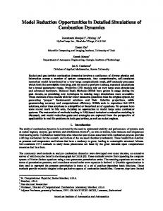
adopted here is to use scaling laws to aid the development process by permitting superscale testing of components at a size accessible to conventional instrumentation and manufacturing techniques while preserving the essential physics. This has been done for turbomachinery fluid mechanics, bearing fluid mechanics and rotor dynamics, and starter/generator electromechanics. Combustors and material properties do not scale so that all combustor and material development are done at full engine scale. The baseline engine design is illustrated in Fig. 1 and its characteristics are summarized in Table 1. The engine consists of a supersonic radial flow compressor and turbine connected by a hollow shaft . (The shaft is hollow to limit heat conduction.) Gaseous H2 fuel is injected at the compressor exit and mixes with air as it flows radially outward to the flameholders. The combustor discharges radially inward to the turbine whose exhaust turns 90 degrees to exit the engine nozzle. A thin film electric startergenerator is mounted on a shroud over the compressor blades and is cooled by compressor discharge air. Compressor discharge air is also used to cool the structure in order to thermally isolate the compressor from the combustor and turbine. The rotor is supported on air bearings. It should be noted that a highly integrated design was adopted in order to minimize the number of components and external connections. The development program includes two high speed rotating machines in addition to the gas turbine engine, a turbine-generator and a motor-driven compressor of similar size and configuration. The turbine-generator consists of a disk rotor; one side of the disk is the radial inflow turbine wheel, the other side is the generator rotor. The rim of the disk is the journal air bearing and the axial loads are supported by air bearing thrust plates on either side at the disk center. The rotor is supported within the stator and end plates, with channels to distribute air to the bearings, completing the assembly. Designed to produce 20 W of electrical power with a compressed air inlet, the unit is primarily intended as a development tool for the bearings and rotor dynamics, turbine aerodynamics, and generator electromechanics. The motor-driven compressor has a similar geometric arrangement to that of the turbine, with the airfoils modified to those of a radial outflow compressor and the electrical machine configured as a motor. The design application is the pressurization of 100 W fuel cells. The following sections briefly discuss component design considerations and aspects of the baseline design.
consumption is 0.44 g/w-hr, and the thrust-to-weight ratio is 12:1. The airflow rate is limited primarily by airfoil height as set by stress in the turbine blade roots. Calculations suggest that it might be possible to improve the specific work, fuel consumption and airflow rate in later designs with recuperators to realize microengines with power outputs of as much as 100 W, specific fuel consumption of 0.28 g/w-hr, and thrust-to-weight ratios of 100:1. This level of specific fuel consumption approaches that of current small gas turbine engines in the megawatt power range but the thrust-to-weight ratio is 5-10 times better than that of the best aircraft engine. The extremely high thrust-to-weight ratio is simply a result of the so-called cube-square “law”. All else being the same as the engine is scaled down linearly, the airflow and thus the power decreases with the intake area (the square of the linear size) while the weight decreases with the volume of the engine (the cube of the linear size), so that the power-toweight ratio increases linearly as the engine size is reduced. The actual scaling is not quite this dramatic since the power per unit air flow decreases somewhat with size. Reducing the scale of the device also reduces the characteristic times (other than that for chemical reaction) so that the startup and shutdown of such a microengine can be very rapid, on the order of a few hundred microseconds. This suggests that operating such an engine in a pulse-width-modulated mode, either at 100% or 0% power, may be attractive to avoid requirements for offdesign point operation and the relatively inefficient part power regime. A principal point is that the a micro-heat engine is a different device than more familiar full-sized engines, with different weaknesses and different strengths. Engine Layout and Design This research program to build the micro-gas turbine generator is structured into five phases. (1) Following a preliminary design process which incorporated current understanding of device physics and manufacturing limitations, a consistent ”baseline” design of the engine and its components was established. (2) Component, material, and fabrication research and design proceed starting from the baseline engine design. (3) The individual components are being individually tested and characterized. (4) Based on the results of (2) and (3), a final, detailed design of the engine will be completed. (5) The engine will be fabricated and tested. The program is currently in phases (2) and (3) which are scheduled to be completed in 1998. One complication in the development of components whose dimensions are measured in tens or hundreds of microns is the difficulty of instrumentation, especially detailed instrumentation. In general, instruments cannot be developed separately from the components but must be fabricated in situ, significantly complicating the component design and fabrication process. The approach
Structures and Materials The thermodynamic cycle requirements of powergenerating turbomachinery drive the design towards high rotational speeds and high temperatures. To achieve the 3
American Institute of Aeronautics and Astronautics
can be recovered3. Analysis of stress and deformation are required to design a reliable structure. In the microengine, the most critical component is the turbine rotor, which experiences high centrifugal stress and elevated temperatures, with the additional possibility of high impact loads. For brittle structures, it is appropriate to use a probabilistic analysis approach to account for the stochastic nature of material strength4. A 3-D finite element stress analysis in combination with a weakest-link statistics (Weibull) model for material strength indicates that the overall failure probability is acceptably low (less than 10-5 ) at the baseline operating conditions. The high temperature performance of silicon is limited by its creep life, thereby requiring the development of more refractory microfabricated materials. Work is currently underway to design and fabricate SiC and Si/SiC hybrid structures by chemical vapor deposition of relatively thick silicon carbide layers (10-200 µm) over silicon molds. The preliminary analysis and testing suggests that this is a promising approach. In addition, because of the small length scales required here, materials which are unsuitable for large heat engines due to thermal shock considerations (e.g. aluminum oxide) would be usable in a microengine given a fabrication technology.
specified performance requires materials with high specific strength at temperature. Ceramic materials generally have lower densities, higher stiffnesses, lower thermal expansion coefficients, and higher allowable operating temperatures than the metals used in conventional, macroscale gas turbine engines. These characteristics are attractive for turbomachinery design at all scales, but success in introducing ceramics into conventional gas turbines has been limited by the low toughness of the materials. The low toughness implies that the strength of ceramics is extremely sensitive to flaws, introduced during processing or subsequent service. However, the strength of brittle materials is scale-dependent. Experimental studies have shown that small specimens, on average, exhibit higher strengths than larger ones, simply because the probability of there being a flaw larger than a critical size decreases with the specimen size. In addition, the use of microfabrication processes on single crystal materials results in very high quality surfaces, and commensurately high strengths. This favorable scaling of strength is one of the enabling factors behind the concept of micro-heat engines. Table 2 compares the key material merit indices for rotating machinery thermal structures at the macroand mesoscales. Other structural design parameters are scale-dependent as well, as summarized in Table 3. Whereas strength and thermal shock resistance scale favorably, the high surface area-to-volume ratio increases the relative oxidation rates, and drives the structures towards isothermal operation. These scale dependencies determine the importance placed on different parameters within the structural design process. The design of a working microengine, in common with all macroscale turbomachinery, requires accurate determination of the material allowables and then detailed structural analysis of the proposed design. Progress on these tasks is briefly described below. More detailed descriptions are available elsewhere2, 3. Material strength is the key input to the structural design process. Since it is a function of processing routes and physical scale, the microengine materials must be tested using specimens produced by the same fabrication route and at a similar scale. Experiments show that the reference strength s0* of silicon after deep reactive ion etching can be in excess of 4 GPa for flat biaxial specimens2. For specimens containing sharp transitions, such as those found at the roots of turbine blades, the strength is reduced by up to a factor of three, due to an increased local surface roughness. However, by use of an isotropic etch to homogenize the surface roughness, the strength
Fabrication The fabrication of a structure as large and complex as a micro-gas turbine generator poses several challenges. These include the production of features hundreds of microns deep, fillets to reduce stress on highly-loaded parts, electrical properties for the motor-generator, the excavation of volumes millimeters across and hundreds of microns deep, and assembly and packaging. Since the initial component demonstrations are in silicon, early emphasis was placed here. Air flows of 0.1-0.2 g/sec imply airfoil and passage heights on the order of 200-300 microns given the geometries of Fig. 1. The bearings require similar dimensions. Deep reactive ion etching was used to produce the turbine shown in Fig. 2 which has a 4 mm rotor diameter, 200 micron span blades, and a 10 micron bearing gap between the rotor disk and stator baseplate. The MIT MEMCAD program, a MEMS process design tool, has been used to create a “strawman” process for complete engines. Using only known process steps, the process yields wafers of completed engines, including a freely-turning rotor, without additional assembly. It is a complex and aggressive process requiring 7 aligned wafer bonds, 20 lithography steps, and the deposition of 9 thin film layers. Roughly speaking, the overall process is as challenging as that of a state-of-the-art CMOS microprocessor.
*
The reference strength is defined as the strength when 63% specimens fail. 4
American Institute of Aeronautics and Astronautics
Turbomachinery and Fluid Mechanics Efficient, high speed turbomachinery is at the heart of this micro-heat engine concept. The development of microfluid machinery, efficient at very small length scale and compatible with the constraints of current microfabrication technology, offers new challenges to fluid mechanics. While the length scales of interest here are not so small as to invoke non-continuum fluid mechanics concerns, the Reynolds numbers are several orders of magnitude lower than those in conventional turbomachinery. Also, current fabrication limitations preclude the 3-D geometries common at large scale. Thus, microturbomachinery cannot be scaled-down versions of conventional devices. These microengine constraints pose several new challenges to the fluid machine designer. First, the relatively high pressure ratios per stage needed for an efficient gas turbine imply that peripheral Mach numbers in the transonic regime are required. But even at this high speed, the Reynolds number of the cold components is only in the tens of thousands while that of the engine turbine is only a few thousand, a regime in which the flow is laminar and diffusion is difficult. This low Reynolds number, high Mach number design space is not one for which either design experience, empirical data, or qualified fluid design and analysis tools exist. The second challenge is the current inability of micromachining technology to fabricate other than planar, “extruded”-like geometries. Thus, endwall contouring and airfoil twist cannot be used to control diffusion and reduce boundary layer separation. The third challenge is turning the flow in the outfabrication plane direction (such as through the flame holders in Fig. 1) without incurring undo pressure loss and blockage. Turning vanes and contouring as would commonly be employed for such turns at large scale cannot be easily microfabricated. The one benefit of the micro regime is that the comparatively higher strength of materials enables higher peripheral speeds per unit pressure rise than is acceptable in the macro world. Thus, less diffusion is needed than would otherwise be the case. This research program requires the design and development of four different turbomachines: a 4:1 pressure ratio compressor and companion “hot” inlet turbine for the gas turbine engine, a “cold” inlet turbine for the turbine generator, and a 2:1 pressure ratio compressor for the electric motor-driven compressor. All four designs share a common design intent, using blade shapes to control the passage area distribution and thus the diffusion rate at constant passage height. The design of all four turbomachinery components was executed with a 2-D numerical cascade design code5 and then a 3-D finitevolume Navier-Stokes solver 6 was used to evaluate the performance. The resultant designs have unusual blade shapes and high swirl leaving the rotor. The numerical
analysis predicts the compressors to have stage efficiencies of 60-65% and the “cold” turbine to produce 65 W at a rotor efficiency of 75%. In all cases, the 3-D losses were predicted to be about twice those predicted in 2-D, a result comparable to that for large-scale turbomachinery. The sensitivity of the pressure losses to scale (Reynolds number) is shown in Fig. 3. The computational results also indicated that the primary constraint on the efficiency of this microturbomachinery arose not from the inherent physics of operating at low Reynolds numbers but from the limitations imposed by 2-D microfabrication. Overall, these predicted performance levels are very encouraging since they are more than sufficient for a viable microengine. Also, these are the first design iterations and it may be possible to realize significant performance improvements through redesign. While the results of the computational simulations are encouraging, only hardware results count in the engine. As a development aid, a turbomachinery test rig has been built at 75 times the linear scale of the micro devices. This scale-up also allows the use of conventional metalworking for rapid turnaround and permits the use of conventional instrumentation. The Reynolds number and Mach number are matched throughout the flow by scaling the pressure down by a factor of 75 while keeping the peripheral speed constant. The rig is designed to accommodate both compressor and turbine testing. Since compressors tend to be more difficult to design aerodynamically than turbines, it is currently configured as a compressor test rig. Initial test results are expected in summer 1997. Combustion The functional requirements for a combustor for a micro-heat engine are similar to those for a conventional gas turbine combustor. The primary functional requirement is to convert chemical energy to thermal and kinetic energy with low total pressure loss. Other requirements include introduction and mixing of fuel and air, ignition, and stable operation for all engine operating conditions. The principal constraints are associated with maintaining low-stressed, cooled structures, and a size and shape that is compatible with the overall engine geometry. Designing a combustor for a microengine application introduces at least two new challenges. The first is the limited flow residence time within the combustor that comes with the small size of the device. This presents difficulties, because while many of the fluid mechanical processes such as injection and mixing may scale with the size of the device, the chemical reaction time is independent of size. The second challenge is associated with the increased surface area-to-volume ratio which is such that heat loss to the walls of the combustor can be significant relative to the heat released in the combustion process. There are 5
American Institute of Aeronautics and Astronautics
carbon-air mixtures. The first is simply to use another fuel such as hydrogen which, due to its high reactivity with oxygen, has an exceptionally wide flammability envelope. The second option is to use surface catalysis to promote a lean hydrocarbon-air combustion process. Indeed, surface catalysis is particularly well-suited to microengine applications because of the relatively high surface-to-volume ratio. A significant benefit is accrued by burning at such lean conditions. Namely, the combustion occurs at relatively cool conditions (1400K to 1600K) which fall within the usable material temperature limits for the refractory ceramics employed in the microengine. This greatly simplifies the combustor design because it eliminates requirements for both active cooling of the walls and a combustor dilution zone. The short residence time coupled with the low temperatures also implies that Nox emissions will be extremely low compared to conventional burners. Both hydrogen-air combustors and catalytic hydrocarbon combustors are currently being pursued. Preliminary results for a hydrogen-air system have been obtained and are shown in Fig. 4. The figure shows measurements of combustor exit temperature for atmospheric pressure tests of a xxx mm3 microcombustor of a geometry similar to that depicted in the schematic of the microengine shown in Fig. 1. The results are shown for various fuelair mixture ratios. Also plotted in the figure is the adiabatic flame temperature that would be expected for each mixture ratio and the associated combustor efficiency. The measurements of combustor temperature were obtained using a 0.01 mm diameter type K thermocouple with an estimated uncertainty (after corrections for conduction and radiation) of ±75K. As shown in the figure, requisite combustor exit temperatures for operation of a micro-heat engine have been obtained (although the combustor efficiency is quite low by today’s standards for gas turbine combustors). The source of the low combustor efficiency is the heat loss from the combustor walls which are uninsulated here. The walls may be insulated or a recuperated engine design can be used to minimize such heat loss. This combustor has been operated for tens of hours at the required space heating rate for the microengine. Additional tests have confirmed similar performance over a range of inlet temperatures and pressures up to 4 atm. A heated wire has proven to be a satisfactory ignitor. This experimental work has been supported by 2-D and 3-D numerical simulations with show similar results. Overall, a microengine sized combustor has been operated successfully.
also new opportunities associated with designing a combustor for the micro environment. Principal among these is the improved material performance which enables operation of uncooled structures at temperatures as high as 1700 K, several hundred degrees hotter than allowable in combustors of more conventional size. Table 4 presents a comparison between various performance parameters for a microcombustor and a combustor as might be found on a typical 30:1 pressure ratio gas turbine engine. The performance parameters for the microcombustor are for a non-recuperated microengine operating at a pressure ratio of about 4:1. The estimates for the various parameters were obtained by making conservative assumptions about achievable performance for a hydrogen-air system. The microcombustor is 1/100 the length of the conventional combustor and 1/1,000,000 the volume. At this size the space heating rate is 10 times larger than that of conventional gas turbine combustors. The microcombustor development effort has been described in detail by Waitz et al.7 and here we only review the basic ideas that underlie the microcombustor design strategies that are being pursued, and then present some preliminary results. The strategies are based on three general concepts. The first is an increase in the size of the combustor relative to the engine in order to increase combustor residence time. The increase in relative size is compounded by the low pressure ratio of the engine. Relative to the engine, the combustors that are being studied are 40 times larger (by volume) than their counterparts in conventional engines. This provides for a residence time of 0.5-1.0 ms which is more than an order of magnitude longer than the characteristic chemical reaction time. Note that even with the large increase in size relative to the engine, the combustor can still be contained in a volume well less than 1 cm3. The second general concept on which the combustion strategies are based is the introduction and mixing of the fuel well upstream of the combustor itself. In the schematic of the microengine shown in Fig. 1, the fuel is injected into the vaneless portion of the diffuser just downstream of the compressor in order to minimize the volume of the combustor. In conventional combustors, most of the combustor volume is devoted to mixing, whether it be fuel-air mixing in the primary zone or mixing with dilution air farther downstream. The difficulty associated with premixing of the fuel in this manner is that most gas turbine cycles mandate an overall fuel-air ratio which is relatively lean due to turbine inlet temperature limitations. These mandated fuel-air ratios lie outside the lean flammability limit for homogeneous gas phase hydrocarbon-air combustion. As such, the third general concept on which the combustor strategies are based is very lean burning (e.g. equivalence ratios near 0.3 or 0.4). There are two well-known options for burning beyond the lean flammability limit for hydro-
Bearings and Rotor Dynamics Low friction bearings are required to support the rotor against fluid and electrical forces, rotor dynamics, and externally applied accelerations while operating at speeds 6
American Institute of Aeronautics and Astronautics
of over two million rpm. Previous rotating MEMS devices8 relied on dry-friction bearings, but high speed turbomachinery requires a lubrication system to ensure a useful operating life. Gas film, electrical, and hybrid gaselectrical bearings were examined. Gas bearings were selected for the baseline engine design based on superior load bearing capability and relative ease of fabrication. A journal bearing supports the radial loads and thrust plates support the axial loads. The physical regime that the micro-gas bearings must operate in are unusual in several regards: the peripheral speed of the bearing is transonic so compressibility effects are important; the ratio of inertial to viscous forces (Reynolds number) is high; the surface area of the bearing is very large compared to the mass of the rotor (the cube-square “law”); and the journal length-to-diameter ratio is quite low. The net effect of these influences is a bearing design well outside existing theory and empirical design practice, especially the journal bearing. Most gas bearing systems operate either subcritically or no higher than the first few critical modes. Subcritical operation here would require submicron operating clearances which are difficult to fabricate and incur viscous losses greater than the engine power output. The current design places rotor speed two orders of magnitude higher than the critical frequency of the rotating system. So, as in any supercritical mechanical system, stability is a major concern. Two broad design options exist. The first places the journal bearing close to the center of the machine. This has the advantage of relatively low surface speeds and consequently low bearing drag and the absence of compressible fluid effects. However, the large gap-to-radius ratio (c/R) leads to poor bearing performance. The second option is to place the bearing on the outer radius of the rotating wheel. This has better load and stability characteristics although the high rim speed results in a transonic bearing flow and a high gap Reynolds number (traditional bearings have vanishingly small Reynolds numbers). Lastly, the bearing has a very low aspect ratio and takes on a “pancake” appearance which adversely affects its stability. Nevertheless, for ease of fabrication, this latter design is the current “baseline” bearing. Because the high Reynolds and Mach numbers in the bearing result in non-negligible inertia and thermal effects in the bearing gap, a full Navier-Stokes computation of the bearing flow was carried out and compared with a spectrally-accurate Reynolds lubrication equation calculation. The results show that, over a wide range of bearing numbers and inertial parameters, the Reynolds equation solutions remain accurate9. Based on these results, subsequent studies have focused on the Reynolds equations which are much faster to solve, particularly for investigation of bearing stability problems. Early estimates suggested that the journal bearing
would be operating in a linearly unstable regime but in a stable limit cycle. The stability of a gas film system can be characterized by a non-dimensional mass parameter: M = (c/R)5 (m p) / (72 L m2) which is extremely sensitive to the bearing gap-to-radius ratio (c/R) and, for MEMS devices, tends to be large compared to its value in conventional bearings. (L is the bearing length radius, m the rotor mass, p the bearing pressure, and m the fluid viscosity.) It is well known that operating a gas bearing eccentrically will increase its stability since c is effectively reduced. (By definition, eccentricity e = 0 when the bearing is centered in the gap, and e = 1 when the bearing touches the wall.) The import of this is evident from Fig. 5 which shows the calculated bearing stability boundary as a function of non-dimensional rotational speed (bearing number = w6m / p[c/R]2, where w is the bearing angular velocity) for different eccentricities. The specific geometry defines a specific M, the dotted line. (M decreases slightly at high speed due to rotor expansion). The solid lines depicts the stability boundaries for a given eccentricity. Thus, at a bearing number of 0.1, the bearing is only stable at eccentricities above roughly 0.9. The stability improves as the speed increases. For conventional bearings, M is two to three orders-of-magnitude lower so the minimum eccentricity is lower, on the order of 0.5. Also, the eccentricity needed for stability decreases as the bearing aspect ratio increases. These stability characteristics imply that these bearings must operate at high eccentricities. In macro bearings, the eccentricity is often imposed by gravity, given that gravity-loading in a MEMS device is effectively zero (the cube-square “law” renders the rotor mass negligible), alternate methods of loading the bearing are needed to ensure stability. This is presently achieved by two means: (1) a differential side pressurization scheme, and (2) the purposeful use of mass unbalance, which forces the rotor to whirl about its center of mass rather than its geometric center. Other bearing geometries, finite amplitude stable whirl cycles, and electrostatic bearings are also being evaluated. Turbine-driven rotor dynamic test rigs have been constructed both at 1:1 microscale (Fig. 2) and at 26:1 macroscale (to facilitate detailed instrumentation). Preliminary data confirm that a rotor of this geometry can be operated a high speed. Electrical Machinery A motor-generator starts the gas turbine and produces the electrical power output. Integrating the electrical machine within the engine offers the advantages of mechanical simplicity (no additional bearings or structure is required over that needed for the engine) and a ready supply of cooling air. In general, either electrical or magnetic machines could be used. An electric machine was 7
American Institute of Aeronautics and Astronautics
chosen for this application due to considerations of power density, microfabrication, and high temperature and high speed operation. The baseline design is a 500 pole planar electric induction machine mounted on the shroud of the compressor rotor. External switching and control circuitry is an integral part of the design. Power is produced at several hundred volts at 3-5 MHz, so power conditioning is required as well. Simulation suggest that such a machine can produce on the order of 20-40 watts with an electrical efficiency in excess of 80%. The major source of loss in the machine is viscous drag in the rotor-stator gap. A superscale version of the device has been constructed as an aid to the development of the power electronics.
APPLICATIONS Button-sized heat engines are certainly fascinating but are they useful? The answer is yes, there are many recognized applications in both the near and far term. Perhaps the most widespread application would be for portable power production. Tens of watts of electric power is sufficient for many portable electronics devices. The energy density of a liquid hydrocarbon fuel is 20-30 times that of the best battery technology so the size of the power source can shrink concomitantly. Also, recharging is simply refueling, which can be done very quickly. Note that a microengine would consume on the order of 10 g/hr of fuel while the engine weight is less than 1 gram, Thus, except for applications which require only a few minutes of operation, engine fuel consumption is more important than engine size. When more power is required than a single microengine can deliver, several or many can be used in parallel. One convenient manner of implementing this parallelism would be wafer scale integration, e.g. including the interconnecting fuel and control lines on the fabrication wafer. Such a wafer, 200 mm diameter by 3 mm thick, could produce as much as 10 kW of power. Since its power-to-weight ratio is so high, one attractive use of such an array would be for distributed, compact, highly redundant auxiliary power units in air and land vehicles. Another use for micro-gas turbine engines is vehicle propulsion. The output of a single engine is sufficient for the micro-aircraft of current interest to DOD, with gross takeoff weights of 50-100 g 10. When more thrust is needed, multiple engines or wafers can be used. A 200 mm diameter wafer may produce 20 lb of thrust, or about 60 lb/ft2 . (It is interesting to note that such a wafer comes very close to the idealized concept of an actuator disk.) This approaches the wing loading of aircraft so that air vehicles should have sufficient area to support surfacemounted microengines for propulsion, eliminating most propulsion system interior volume requirements. Applications might include tactical munitions and UAVs in the 100-1000 kg range, which would require thousands of engines. In such an arrangement, the propulsion system can ingest the vehicle’s boundary layer and thus eliminate the wake, which is well known to improve the propulsive efficiency. Another advantage of a microengine approach to propulsion is that thrust is truly modular, so one engine design can be used over a wide range of vehicles and thus be produced in large quantity. Also, an increase in vehicular thrust requirements would be met simply by adding more engines, rather than the current practice of modifying or redesigning the engine. It must be pointed out that the fueling, control, and integration problems are formidable when large numbers of engines are considered separated from wafers. Further, the specific fuel consumption of the microengines is consider-
Auxiliary Systems, Integration, and Packaging A complete, operational gas turbine requires auxiliary equipment in addition to the components described above, specifically: a fuel control system including sensors, processor and a fuel control valve; control electronics for the electric motor-generator; an inlet air filter; and a fuel supply (including either a pressurized tank or pump). The engine development program does not at this time include these components since its goal is a bench top demonstration of the microengine concept and these functions can be provided by available macroscale equipment. Microsensors, valves and pumps have been demonstrated by many investigators, although we know of none that have the characteristics required for this application. Integration of a bare microengine (Fig. 1) into a user’s system is known as installation in the aeronautical world and packaging in the semiconductor field where it can dominate cost in some cases. For the microengine, this includes: electrical and fuel connections, mechanical mounting, and intake and exhaust gas ducting. The electrical connection can be handled similarly to that of current semiconductor devices but the technology for mechanical and fluid interconnections must be developed. The thermal interface is quite different for micro-heat engines than for integrated circuits. In the case of the latter, waste heat must be conducted away from the outside of the package (i.e. the device must be cooled). The waste heat of a gas turbine is conducted away by the exhaust flow, thus the engine walls may be insulated to protect the environment. For the simple baseline gas turbine generator, the exhaust temperature is XXX C. Calculations indicate the a recuperated engine with an exhaust mixer (similar to those employed on helicopters as infrared suppressers) will have an exhaust temperature below 100 C. When closely integrated, such auxiliary equipment may double or triple the engine size and weight. A factor of three over the bare engine weight is included in the weight estimates in Table 1. 8
American Institute of Aeronautics and Astronautics
ably inferior to that of large aircraft engines. Thus microengines for the propulsion of large manned aircraft seem unlikely in the foreseeable future, although their very high thrust-to-weight ratio and inherent very low noise may make them attractive for auxiliary propulsion uses such as short duration vertical lift engines. Surface-mounted microengines may be of use for boundary layer and circulation control. They are very energetic fluid sources and sinks which may be rapidly modulated for either passive or active control. They are thus amenable to many types of boundary layer modification, as widely discussed in the literature. Engine components – compressor, turbine, motor, generator, combustor – are the enabling technology for many thermodynamic cycles other than a gas turbine. For example, the turbomachinery can be used as an air-cycle machine for cooling. Cooling can also be achieved with a motor-driven compressor and heat exchangers configured in a variety of microrefrigeration cycles for both near room temperature and cryogenic applications. The motor compressor geometry adapted as a motor-driven centrifugal pump enables a host of Rankine cycle power production applications, for example solar dynamic power cycles at the 50W level for space or terrestrial applications, or power production from waste heat (bottoming cycles). Conceivably, a bottoming cycle could be added to the gas turbine to realize a high efficiency, combined cycle micro-power plant. Obviously, there are also a host of uses for these microcomponents in applications other than thermodynamic cycles. There are undoubtedly many other uses for microgas turbine engines and components than just those discussed above and readers are encouraged to speculate. If microengines are built with sufficient performance, they will be quite useful.
superior properties of microfabrication materials results in an unusual design. The engine configuration is prismatic 2-D structure to be compatible with current fabrication technology. This requires all of the nozzle expansion to be in-plane (the illustration is for a 15:1 area ratio for sea level testing) so it is the nozzle exhaust area which limits the engine power that can be fit onto a chip rather than propellant pumping capability. There are several options for producing much larger thrusts if needed including: stacking motors together (80 lb per square inch of motor footprint can be produced in this manner); placing only the pumps, controls and chamber on a chip and mating one or more such chips to a conventionally fabricated large exhaust nozzle; or placing only the pumps and controls on a chip and feeding a conventional chamber and nozzle. At these small scales, the combustion chamber pressure must be quite high, 100-200 atm, for the design to close and to realize a near ideal specific impulse. The high chamber pressure is needed for three reasons. The first is that the mass flow scales linearly with the pressure so that higher pressure means higher thrust for a given motor size. The second is that, for these regenerative designs, as the chamber pressure and thus the mass flow is raised, the cooling capacity of the propellants goes up faster than the heat transfer to the walls. This energy balance establishes a minimum chamber pressure needed to keep the walls cool, about 120 atm for silicon walls. Vibrational relaxation time establishes the third requirement for high chamber pressure. If the nozzle flow is on the order of the vibrational relaxation time of the reaction products, then a significant fraction of the internal energy will be unavailable for propulsion resulting in a low specific impulse. Since the vibrational relaxation time at 1 atm is on the order of 1 microsecond, the same as the nozzle flow time, the chamber pressure must be much higher than 1 atm. The baseline microrocket engine design has a 300 atm pump delivery pressure and a 150 atm chamber pressure. Even though the chamber pressure is high and the thin planar geometry of Fig. 6 is inefficient for a pressure vessel, the superior strength of the micromaterials combined with the cube-square “law” results in an extraordinary thrust-to-weight ratio for such a microrocket engine, 1500:1, which is 10-100 times better than large engines. The small length scales, the high thermal conductivity of SiC (approaching that of copper) and Si, and the flexibility micromachining brings to cooling channel design all contribute to reducing the thermal stress that needs to be carried by the material. Why build micro-bipropellant microrocket engines? There are several potential advantages. One is dramatic improvements in manufacturing cost and reliability. By including the entire motor on a single chip (including
MICRO-BIPROPELLANT ROCKET ENGINES High speed, high power density microturbomachinery can also be an enabling technology for microfabricated liquid propellant rocket engines. Liquid high pressure pumps of similar size, general geometry, and fabrication technology as the turbomachinery described above can pump 20-50 g/sec. A complete “rocket motor on a chip” can be realized by combining the pumps with a regeneratively cooled chamber and exhaust nozzle, valves and controls, and plumbing. Such a planar motor, now under design, is illustrated conceptually in Fig. 6. It is sized to produce 15 Nt of thrust while consuming 5g/sec of liquid oxygen and methanol propellants. The engine consists of a regeneratively cooled chamber and nozzle, pumps, controls, and plumbing (the multilayer-plumbing and interconnections are not illustrated). The capabilities and constraints of micromachining technology combined with the 9
American Institute of Aeronautics and Astronautics
chamber, pumps and controls) the cost per unit can be quite small compared to existing devices. Also, a bipropellant engine in this technology is little more complex or costly for the user than a monopropellant system. Once the fabrication process is developed, semiconductor process control standards coupled with the absence of assembly imply that very high reliability can be achieved. Another advantage is the very high thrust-to-weight ratio of the microengine. Overall system weight is reduced by improved specific impulse and by reduced tank and feed system weight which can come from switching from pressure feed monopropellants to pump feed bipropellant propulsion. Also, since the engine weight and cost is so low, extra engines for redundancy incur little penalty. Single engine applications might include spacecraft attitude control and station keeping. Arrays of 20-50 engines could be used for apogee kick. Larger arrays might be used for main propulsion for very small launch vehicles. In this application, differential throttling across the array could provide thrust vector control. Undoubtedly, many other civil and military uses can be identified for engines with this level of thrust-to-weight ratio, size, and cost.
and Structures, January 1997. Chen, K-S, Ayon, A., Spearing, S.M., “Tailoring and Testing the Fracture Strength of Silicon at the Mesoscale,” submitted to Journal of American Ceramic Society, June 1997. 4. Nemeth, N.N., Manderscheid, J.M., Gyekenyesi, J.P., “Ceramic Analysis and Reliability Evaluation of Structures (CARES),” NASA TP-2916, 1990. 5. Youngren, H., "Analysis and Design of Transonic Cascades with Splitter Vanes," Masters Thesis, Department of Aeronautics and Astronautics, MIT, 1991. 6. Dawes, W.N., "The Practical Application of SolutionAdaption to the Numerical Simulation of Complex Turbomachinery Problems," Prog. Aerospace Science, Vol. 29, 1992, pp. 221-269. 7. Waitz, I.A., Gauba, G., Tzeng, Y-S, “Combustors for Micro-Gas Turbine Engines,” presented at the International Mechanical Engineering Congress and Exposition, Nov. 1996. 8. Dhuler, V.R., Mehregany, M., Phillips, S.M., Lang, J.H., "A Comparative Study of Bearing Designs and Operational Environments for Harmonic Side-Drive Micromotors," Proc. IEEE Workshop on Micro Electro Mechanical Systems, Travemunde, Germany, Feb. 1992, pp. 171-176. 9. Piekos, E.S. and Breuer, K.S., "Design and Analysis of Microfabricated High Speed Gas Journal Bearings," AIAA Paper AIAA-97-1966, June 1997. 10. Random Samples, Science, Vol. 275, 1997, p. 1571. 3.
CONCLUDING REMARKS The design of the micro-heat engines presents a considerable challenge to all the disciplines involved, so the timely success of this program is by no means a foregone conclusion. However, progress to date has been encouraging and we are quite optimistic. In addition, the ability to manufacture MEMS-based high speed rotating machinery opens up a host of possibilities including various thermodynamic machines. The concept of MEMS-based, high power density, heat engines appears extremely attractive and physically realizable. Considerable intellectual investment in this area is therefore warranted.
Table 1: Baseline MicroEngine Parameters Arrangement Dimensions Pressure Ratio Air Flow Combustor Temp Rotor Speed Power Output Thrust Weight Fuel Consumption
ACKNOWLEDGMENTS This work on the micro-gas turbine generator is supported by the US Army Research Office, Dr. Richard Paur program manager. The microcompressor is sponsored by DARPA, Dr. Richard Nowak program manager. The microrocket engine is supported by NASA Lewis Research Center, managed by Mr. Steven Schneider and Dr. Frank Curran.
1.
2.
REFERENCES Bryzek, J., Petersen, K., McCulley, W., “Micromachines on the March,” IEEE Spectrum, May 1994, pp. 20-31. Spearing, S.M. and Chen, K.S., “Micro-Gas Turbine Engine Materials and Structures,” presented at the 21st Annual Cocoa Beach Conference and Exposition on Composites, Advanced Ceramics, Materials 10 American Institute of Aeronautics and Astronautics
Single spool turbojet 12 mm OD x 3 mm long 4:1 0.15 gram/sec 1600 K 2.4x10⁶ rpm 16 W electric 0.125 Nt. 1 gram 7 gram/hr
Table 2: Key Merit Indices for Turbomachinery Materials Index of Merit Centrifugal Stress [√σf /ρ] (m/s) Thermal Stress [αE/σf/y] Stiffness [E/ρ] (MPa/Kgm-3) Max Temp (°C) limiting factor
Table 3: The Effect of Lengthscale on Structural Design Property
Ni-based Macro Super Titanium (Micro) Alloys Alloys Ceramics 330
420
420 (670)
2.7x10⁻³ 1.2x10⁻³ ~26
~25
Micro Silicon
Permits increased operating speed
Structural stress Unchanged
Scales with density and (velocity)2
Heat transfer rate Increases
Structures become isothermal
Thermal shock resistance
Increases
Allows consideration of materials which are not feasible at the macroscale
Resonant frequencies
Increase
But operating frequencies also increase
Oxidation resistance
Increase
Due to surface area-tovolume ratio
~70
~1000 ~300 ~1500 ~600 (creep) (strength) (oxidation) (creep)
Table 4: Comparison Between Conventional and Microcombustors
Comments
Ceramic strength Increases
330
2.0x10⁻³ 0.9x10⁻³ (1.1x10⁻³) ~95
Effect When Lengthscale Decreases
Structural impact Increases
Material creep
Impact stress is scaleindependent but strength increases
Independent So long as structural scale significantly greater than material microstructure
Starter/ Generator Flame Fuel Fuel Holders Manifold Injectors Compressor Diffuser Rotor Vanes Blades
Inlet
Gas Path
Combustion Chamber
Turbine Turbine Exhaust Nozzle Rotor Nozzle Vanes Blades
Centerline of Rotation
Fig. 1: Micro gas turbine generator cross-section. 11 American Institute of Aeronautics and Astronautics
Rotor
Bearing Mass Parameter, M
101
ε=
100
STABLE ε = 0.900 UNSTABLE
10-1 ε = 0.850 ε = 0.800 10-2 10-1
Normalized Total Pressure Loss
100
Rotative Speed, Λ
Fig. 2: 50 watt microturbine.
Design Speed
Fig. 5: Micro-gas bearing stability as a function of rotor eccentricity, ε, and rotor speed, Λ, for a geometry similar to the journal bearing in Fig. 2.
4 Nozzle
3 "Cold" Turbine Design Point
2
Ox. Valve
Fuel Valve
Rotor
1 "Hot" Turbine Re
0 3
Chamber
4 5 Log Reynolds Number
6
Fig. 3: Pressure loss (∆PT/@ρU2) as a function of Re for a turbine of the geometry of Fig. 2.
0.6 1200
0.4 0.2
600 0.6
0.7
0
Combustor Efficiency (η)
1.0 0.8
0.5
Ox. Pump
2 mm
1800
0.4
Fuel Pump
Nozzle
Measurement Calculated Tadiab Efficiency
2400
T (K)
5
0.92
Cooling Passage 12 mm
Fig. 6: Micro-bipropellant regenerative rocket engine concept producing 15 Nt thrust.
Equivalence Ratio
Fig. 4: Exit temperature and efficiency measurement for a microcombustor similar to that in Fig. 1, as a function of equivalence ratio (fuel-to-air). 12 American Institute of Aeronautics and Astronautics