Nov 7, 2013 ... The AIC1 Additional Injector Controller provides precise fuel delivery ... The AIC1
gives the user a convenient way to set the proper fuel mixture.
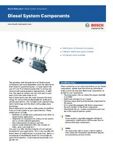
AIC1 Additional Injector Controller Description: The AIC1 Additional Injector Controller provides precise fuel delivery over the boosted operating range of an internal combustion engine. It is designed for use with engines that have been converted to forced induction with the addition of a turbo or supercharger. The AIC1 gives the user a convenient way to set the proper fuel mixture throughout the entire boost region. The AIC1 can be ordered in a variety of configurations. Refer to the ordering information section to see the available combinations of pressures sensors, number of injectors and injector types. Both absolute and gauge pressure sensors are available. The absolute sensor can read both the vacuum and boost regions up to 16 psi. The gauge pressure sensor reads in the boost region only with an upper limit of 26 psi. The absolute pressure version is recommended for applications with under 16 psi of boost. The AIC1 is available in both low impedance and high impedance versions. Low impedance drivers can drive either low or high impedance injectors. High impedance drivers are for high impedance injectors only. Versions that drive one or two injectors use map A only. Versions with four injector drivers use map A to control two of the injectors, and map B to control the other two injectors. The calibration of the AIC1 is done through a serial interface, which is active while in operation. The AIC1 is programmed with the R4 engine management software for Windows. The software provides real time display of RPM, manifold pressure, injector on time and duty cycle in percent. A variety of editing tools ease the task of setting up an initial map and quickly fine tuning for optimum performance. With the 4-stroke setting selected, the AIC1 will fire the additional injectors on every other tach pulse. Use the 2-stroke setting to make it fire the injectors on every tach pulse. This will improve fuel distribution among cylinders. Set the number of cylinders to half the actual number to get the correct RPM reading when using the2-stroke setting.
Features: • • • • • • • •
•
Eight different standard versions are available Internal absolute or gauge pressure MAP sensor versions Available with either low or high impedance injector drivers Low impedance drivers can drive either low or high impedance injectors Two three-dimensional map tables defined by boost pressure and RPM Compatible with 2 and 4 stroke engines from 1 to 12 cylinders Laptop programmable Programmed according to pulse width in milliseconds Transient surge and battery reversal protection
1
11/7/2013
Typical Wire Assignments: LABEL BATT+ BATTINJA+ INJAINJB+ INJBTACH F-DB9
CONNECT TO Battery positive (+12V) Battery negative (chassis ground) Injector plug positive (+12V) Injector plug negative (injector driver) Injector plug positive (+12V) Injector plug negative (injector driver) Tach signal (pulses per rev = #cyl/2) Serial connector on computer
MAP TABLE WIRE COLOR Red Black Red (2) A Tan (2) Red (2) B Tan/Black (2) Yellow/Black -
Typical Connections:
RED
IGNITION SWITCH
BLACK
AIR FLOW BATTERY
INJECTOR LOOM IN
INTAKE PRESSURE TUBE
IN
IN
AIC IN
FUEL RAIL YELLOW/BLACK
THROTTLE BODY
VACUUM / BOOST LINE
TACH SIGNAL
It is strongly recommended that a true-tach signal is used as the tach reference. A truetach signal produces a number of pulses equal to the number of cylinders for each cam revolution. Use the 2-stroke setting to make the additional injectors fire on every tach pulse. This will improve fuel distribution among cylinders. Set the number of cylinders to half the actual number to get the correct RPM reading when using the2-stroke setting.
2
11/7/2013
Software: The AIC1 is programmed with the R4 engine management software. When the software is launched an identification screen will appear that says Split Second. After four seconds, the main menu will appear. If this is a new application, select File then New Customer to create a new customer. Type in the customer name and save. The default location for customer names is My Documents. When you return to the main screen, select File and Open Customer to open the customer file that you just created. Once the customer is open, the Maps, View, Options and Help tabs become active. You can fill in the various fields such as name, address etc. if you like.
Connections: Connect the AIC1 to the computer using a USB to serial adapter cable. These cables require a software driver that must be properly installed on the computer. Select the proper com port for the serial adapter. The correct com port setting may be found under Ports in the Device Manager of the computer. Remove the lid on the AIC1. Once the cable is plugged in and the AIC1 is powered up, you may connect to the AIC1 by selecting the Connect to ECU icon. Once communication has been established with the ECU, the Real Time pull down becomes active. There are two map tables. Most versions use map A only. The versions that drive four injectors use both maps A and B. The connectors with tan wires are controlled by map A and those with tan/black wires are controlled by map B.
Programming: Use Options and System Settings to select Additional Injector Controller and the correct pressure reading. If you have a gauge pressure sensor, select Gauge Pressure. If you have an absolute sensor, select Vacuum/Pressure. The Absolute Pressure setting may also be used if you prefer. Use the Options pull down and Engine Settings to select the number of cylinders of the engine. The 2-stroke setting along with half the actual number of cylinders is recommended. That will result in the correct RPM reading with a true-tach RPM signal. Use the Maps pull down to access the fuel map tables. The numbers entered into the cells on the map represent the injector on time in milliseconds. Whenever a cell is highlighted, the injector pulse width is shown in the upper left hand corner of the table. You can click and drag to highlight an area of cells. Once highlighted, you can use the icons across the top of the window to fill all the selected cells with a value. For example, if you fill the selected cells with the value 10, whenever the manifold pressure and RPM match one of those cell locations, the injectors will be pulsed for 10 milliseconds.
3
11/7/2013
A highlighted area of cells can also be changed by a percentage by using the Change By button. To increase a highlighted area of cells by 10 percent for example, select the cells, click on the Change By button and enter 10. To reduce by 50 percent, enter –50. You can also fill a range of cells with values that are interpolated from the end points. This works over a row, column or 2-dimensional area. To fill values over a two dimensional area, fill the four corners of the area with cell values. Then click and drag to select the area encompassed by those corner cells. Click on the Auto Fill button. The software will calculate and fill the correct values for all highlighted cells. If your AIC1 drives four injectors, you will have to fill in both map tables A and B. If you want to use the same values in both tables, you can copy and paste the data. Hit the Select All button while in the table you want to copy. Then press the Copy button. Go to the other map table and highlight the cell in the upper left hand corner of the table. Then press the Paste button. Once the maps are set up, you can write to the ECU in the AIC1. To write to the ECU, the ignition must be on so that the AIC1 is powered up. The engine must be off so that tach pulses are not present during programming. To write to the ECU press the Write Data to the ECU button. You can also upload from the ECU using the Read Data From the ECU button. You can then save or modify the data. During the tuning process, it is a good idea to periodically close the file you are working in and start a new file. This will make it possible to go back to a previous tune. Create and open a new customer file. Set the correct system settings, connect and Read Data from ECU. You are now ready to continue tuning. Use the notes field on the main screen to record pertinent information about the file.
Operation: Once the data is loaded into the AIC1, the engine can be started. From the main screen, the Real Time pull down can be used to observe a variety of operating parameters. The All option brings up a window that displays boost pressure and RPM as well as pulse witch and duty cycle for both A and B injectors. The All window can be enlarged to full screen size to make it easy to read while working on the engine. The RPM and Pressure options display analog gauges that show those parameters. The All, RPM and Pressure options can all be displayed simultaneously.
Ordering Options: Part Number AIC1-A2H AIC1-A4H AIC1-G2H AIC1-G4H AIC1-A1L AIC1-A2L AIC1-G1L AIC1-G2L
Number of Injectors 2 4 2 4 1 2 1 2
Injector Impedance High High High High Low Low Low Low 4
MAP Sensor Type Absolute Absolute Gauge Gauge Absolute Absolute Gauge Gauge
Map Tables Used A A and B A A and B A A A A 11/7/2013
Electrical Characteristics: PARAMETER Supply Voltage Supply Current Tach threshold Tach Hysteresis Boost Range L Injector peak L Injector hold H Injector limit
CONDITIONS BATT+ to BATTInto BATT+ terminal Normal operation Normal operation On vacuum/boost hose Initial sink current Steady state sink current Max current before shutdown
MIN 12
TYP 13.5 16 2.5 0.5
0
MAX 15
26 4 1 2
UNITS V mA V V PSI A A A
Mechanical Characteristics:
3.000
4.750
1.475
5.250
1949 E. Deere Ave. Santa Ana, CA 92705 TEL (949) 863-1359 FAX (949) 863-1363
5
11/7/2013