MATEC Web of Conferences 248, 01002 (2018) ESTIC 2018
https://doi.org/10.1051/matecconf /201824801002
Air flow Simulation in correlation of the Outside Engine Temperature Change with Variation of the Grill Rahmat Riza*, Paryana Puspaputra and Wajib Haryono Universitas Islam Indonesia, Yogyakarta, Indonesia
Abstract.This research is objected to study the effect of air volume variation in the cooling process for the outer wall of vehicle engine. The results were expected to be consideration in Grill’s engineering process in term of better efficiency which is the discussion nowadays. The simulation was executed on a model rebuilt from a rough estimate of one of the existing urban vehicles in Indonesia. This model was performed in computational fluid dynamics software. Four condition of hole’s grill of the vehicle engine were prepared as the main parameters to experiment the air flow which would receive the heat from the outer wall of the engine. These parameters were study to investigate the outer wall temperature of the engine. The results showed that reducing 25% of hole’s area of the grill would increase temperature around 7.4%, the decreasing of 50% of the hole had made the increasing temperature around 28%. The last condition of the decreasing of 75% of the hole had caused the increasing temperature around 400%.
1 Introduction Internal combustion engine works in the optimum system in the consideration of many parameters which referring to the maximum power output produced in the lowest fuel consumption without neglectful safety and cost of maintenance[1]. One of the parameters is the optimum temperature of the combustion.The change of the temperature, outside of the optimum range, will be ensured to implicate the engine in the worse direction. Whenever the temperature of ignition does not reach the optimum point, the process is facing some problem like imperfect burning which producing less power and more pollutants for our environment [1]. The process is called overheating whenever the temperature exceeding the optimum value. In the overheating condition, the engine also produces many problems such as preignition which cause less power and reducing the lifetime of the engine component [2]. This is regarding to the process where most of energy generated by fuel burning is used to drive piston and some of them is exhausted as energy loss. The loss will cause temperature increasing around the engine and released to the environment by heat transfer which is known as the cooling system. This system is an important process to maintain the combustion process in the optimum temperature. The importance of cooling system in internal combustion engine had been shown by many experiment conducted [1–6]. They showed that *
Corresponding author:
[email protected]
© The Authors, published by EDP Sciences. This is an open access article distributed under the terms of the Creative Commons Attribution License 4.0 (http://creativecommons.org/licenses/by/4.0/).
MATEC Web of Conferences 248, 01002 (2018) ESTIC 2018
https://doi.org/10.1051/matecconf /201824801002
cooling system take an important position in the system. These results also showed that the cooling system influenced the performance of the engine overall. The cooling system for the vehicle engine naturally takes place by conduction which is transferring the heat from the inner wall of the engine to the outer wall of the engine. Then, the heat in the outer wall of the engine is removed by convection to the environment. The heat is also removed by fluid, called as coolant, whenever the heat in the combustion room is too high to remove to the environment in nature. The coolant is utilized to distribute the area of heat releasing to the environment[1] within more alternatives. For the latest vehicle, temperature in this outer wall is approximated in the range 90 to 115oC [2]. This temperature is maintained in order to prevent the overall components of the engine from the defect [7]. This situation can be obtained by supplying as much as possible the number of air in the environment to the engine room. This is parallel with formula [2]: 𝑞 = 𝑚. 𝐶𝑝 .△ 𝑇
(1)
where q referred to the number of heat transferred, m is number of mass involved in the process and ∆T symbolized temperature difference between low temperature and high temperature and Cp is specific heat. This showed that the heat released to the environment from the engine will be determined by the amount of air in the outer wall of the engine. However, the air that can be provided in the engine room is limited by the space for the safety, design and the efficiency. Thus, it was crucial to recognized the effect of air variation which supplied to engine room to the change of outer temperature in order to adopt different many variations in the design and safety consideration.
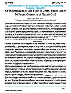
2 Model Development Many factors that was determined how much the air can delivery to the engine room. One of them is grill design. Grill of vehicle has multiple function. The first function is designed as the protector of the engine components from the large size material from the road. The second function is used to determine number of air entering the engine room. From its shape, the volume of outside air could be controlled to delivery to the engine room. The other function was to develop attractive and aerodynamic shape of the vehicle [8]. In some of condition, all the function cannot adequate each other. Therefore, variation of grill design was used to conduct this experiment. It was performed by following steps, namely: 1. model determination, 2. Model simulation and 3. Results and Analysis. This work was implemented for Honda Brio Satya which is manufactured in 2014. The grill and engine room of this sample were modelled as the grill was assumed as given in Figure 1(a):
(a)
(b)
Fig. 1. (a) Recondition of Grill Design of Honda Brio Satya which manufacturing in 2014; (b) Simulation Model of Vehicle Engine Room.
This grill design was re-produced by measuring the original one and drawn in Computer Aided Drawing (CAD) with the approximated dimension. However, the difference should be accepted since the objective of this experiment was to observe the trend of the change of the air volume entering the engine room in relation with the change of the outer wall temperature
2
MATEC Web of Conferences 248, 01002 (2018) ESTIC 2018
https://doi.org/10.1051/matecconf /201824801002
of the engine. The engine in this model was assumed as the black box which generated heat. Its dimension is only approximated from the real condition. Based on this approaching, the model for the simulation in this work was given in Figure 1(b). In order to obtained different of air volume, this work was committed by varying the area of hole in the grill. Three configurations were examined in order to explore how the volume of air entering the engine room influence the temperature of outer wall of the engine. The configurations were determined for 25% closed area of hole, 50% closed area of hole and the last one was 75% closed area of hole. The simulations were implemented within environment temperature of 32 oC which referring to higher level of the temperature in the D.I. Yogykarta and wind velocity around 2,1 m/s. These data were obtained from Climatology station D.I. Yogyakarta (references). This condition was combined with condition vehicle run at 1500 RPM which temperature observation show to 85oC. This temperature was taken by running the engine for five minutes in 1500 RPM. The measurement was executed by turning off the cooling fan where the instrument was able to measure till 400oC.
3 Results and Discussion Simulation was performed by using software for computational fluids dynamics (CFD). Number of Meshing for the calculation was set up automatically by the software assumption. The computational results of CFD software for the condition of the original grill as the comparison with the experimental condition were given on Fig. 2.
Fig.2. Air Flow Simulation Result of the Engine Cooling System for the Original Grill Design
Temperature distribution in Fig. 2. described that air from the outside entering room engine with temperature 32oC had absorbed heat from the engine. This process was brought the air temperature in the room engine increase to the highest of 36,54 oC. The first variation in this experiment was performed by modifying the aperture of the hole in the grill of the engine. This modification was intent to obtain 75% of the fresh air from the surrounding flowing to the engine room. It had been implemented by modifying the hole’s diameter of the grill thereby the area of the hole reduced for 25% from its original size. It was modelled as given in Fig. 3.(a). The second one was conducted on the grill with 50% of hole’s area reduced. The last modification was carried through 75% of closed hole’s area.
(a)
(b)
(c)
Fig.3. (a) Grill model with 25% of the hole’s area was closed; (b) Grill model with 50% of the hole’s area was closed; (c) Grill model with 75% of the hole’s area was closed
3
MATEC Web of Conferences 248, 01002 (2018) ESTIC 2018
https://doi.org/10.1051/matecconf /201824801002
All of those experiment configurations were designated in order to explore the effect of air flow to cool the outer wall of the engine. The results for the first experiment were given in Fig.4, where Fig.5 refer to the results of air flow simulation for second experiment. And the outputs of the last condition of the experiment were illustrated in Fig.6.
Fig.4.Air flow simulation for 25% closed area of hole in y-axis.
Fig.5.Air flow simulation for 50% closed area of hole in y-axis.
Fig.6.Air flow simulation for 75% closed area of hole in y-axis.
Overall, the results for all configurations showed that air flow in the room engine had started to develop turbulent flow. This condition was highlighted by the pattern of the arrows highly fluctuating. The turbulent condition was normally developed when inertia forces greater than viscous forces as determined by Reynold number which formulated [9]: 𝑅𝑒𝑥 =
𝜌𝑢∞ 𝑥 𝜇
(2)
Where ρ refers to air density, x is the length of heat transfer processes, μ is viscosity of the air, and 𝑢∞ is the velocity of air entering the engine room. Based on this equation, the air velocity influences the turbulent development of the airflow. It depends on several condition, especially the area that is gone through by the air itself. The surrounding air enters the engine room will pass the grill. On this situation, the velocity of the surrounding air would have surface resistance from the grill as discussed by Crowe, et al. [10] described as in Figure 7: When the surrounding air pass the grill, some of the air would hit the grill, some of the air would tangent with the surface’s hole of the grill and the rest could pass through the grill freely. The part of air which hit the grill would yield drag. This drag would influence the air in the engine room and form drop pressure in the back of the grill which is located in the engine room. This pressure would cause most of the air restrained near in the grill as figured in the simulation results as in Fig. 4 to Fig. 6. Only few of them could directly reach the 4
MATEC Web of Conferences 248, 01002 (2018) ESTIC 2018
https://doi.org/10.1051/matecconf /201824801002
engine wall. This meant that the air volume which received heat from the outer wall of the engine reduce and caused the air in the engine room would take extra heat from the engine surface. The small of grill hole would led the small volume of the surrounding air to reduce temperature of the outer wall of the engine. This is indicated from the results illustrated by Fig. 4 to Fig.6 which show that the variation of the hole’s area of the vehicle grill will influence the wall temperature of the engine
Fig.7. Air flow illustration in the area of grill
4 Conclusion Air flow simulation results showed that the change of the hole’s area of the grill vehicle had bought difference heat transfer from the outer wall of the engine. Diminishing 25% of grill area could increase the engine temperature around 2.7 oC. However, reducing the diameter of the hole was not linier with increasing temperature where 50% of diminishing diameter had increased the engine’s temperature around 10.23 oC and 75% of diameter reducing had brought the engine’s wall temperature to be 51,19oC.
References 1. 2. 3. 4.
Y. Singh and N. K. Singh, J. Energy South. Afr. 24, 7 (2013). M. M. A. Morad and J. Alrajhi, J. Mech. Eng. Autom. 4, 55 (2014). B. Yang, S. Han, and H. Cho, Int. J. Appl. Eng. Res. 11, 9106 (n.d.) (2015). C. Wilhelmsson, A. Vressner, P. Tunestål, B. Johansson, G. Särner, and M. Aldén, in (2005). 5. C. Wang, Q. Sun, and L. Xu, J. Electr. Comput. Eng. 2017, 1 (2017). 6. A. K. Hossain, D. I. Smith, and P. A. Davies, J. Sustain. Dev. Energy Water Environ. Syst. 5, 46 (2017). 7. G. R. Safakish, Adv. Mech. Eng. 4, 931584 (2012). 8. L. Liu, C. Jing, and X. Hu, in Atlantis Press, (2015). 9. F. P. Incopera, D. P. Dewitt, T. L. Bergman, and A. S. Lavine, Fundamentals of Heat and Mass Transfer, Sixth John Wiley & Sons (Asia) Pte Ltd., (2007). 10. C. T. Crowe, D. F. Elger, and J. A. Roberson, Engineering Fluid Mechanics, Eighth John Wiley & Sons, Inc., (2005).
5