and construction of The Airbus A330/A340 Primary Flight Control System. Figure
1 gives an overview of the top-level functions of the system that are described in ...
3.1.4 Functional Analysis and System Definition. .... system for the Airbus A330/
A340. In the Airbus A320, which was introduced in 1988, digital techniques were
used for the .... rotation position. Figure 4 Mechanical and Electrical control ...
Dec 24, 2013 ... Product information, technical updates and manual corrections will be available
on this website. .... 1.1.2 Hardware Connection Diagram .
A2 Flight Control System. User Manual V1.22. May, 2015 Revision. Thank you for
purchasing DJI products. Please strictly follow these steps to mount and ...
Page 1 of 34. DOT/FAA/AR-07/65. Air Traffic Organization. Operations Planning. Office of Aviation Research. and Developm
airframe model is a high fidelity linear representation of the AH-64D generated using Boeing's Blade Element. FLYRT (BEFLYRT) modeling and simulation tool.
Today aviation companies gradually come to model-based embedded software development proc- ... the approach description through a software model, including the ..... Holder of a State Award in Science and Engineering of Ukraine.
May 21, 2015 - b Microgravity Experiments Office, Toulouse Center Directorate, CNES, 18 avenue ... flight campaigns have been organised by ESA, CNES and DLR since 1997, .... twenty to thirty teams answer to the CNES national call.
Jul 28, 2011 - coupled with a simple fuzzy flight controller on an unmanned helicopter which is commonly accepted to be more difficult than fixed-wing aircraft.
Aug 28, 1997 ... related to the effects of automatic flight control systems on the loads .....
Evergreen International Airlines Boeing 747-100, Thunder Bay, Ontario, ...
Jun 19, 2000 ... simulation software has fully integrated the design process. ..... [2] BDM-1606,
Boeing Design Manual, Mechanical controls, June 1990. [3] CMS ...
P. Dean of Faculty of Electronic Engineering,. Faculty of Electronic ... reconnaissance, advanced attack air vehicle for hazardous missions). Autopilot is the.
For advanced airplane, the Safety of Flight tends to be dependent on complex flight control system. The result is a greatly increased emphasis on flight control ...
flight control system architecture design are based on a control surface layout
obtained from the Boeing 747 technical manual. Stability and control
assessments ...
Charles Hall, Chong Lee, Mark Jackson, Mark Whorton, Mark West1. NASA Marshall Space Flight Center, Huntsville, AL 35812. Jay Brandon2. NASA Langley ...
Sep 16, 2009 - 3rd CTA-DLR Workshop on Data Analysis & Flight Control ... Focusing on the design of fault-tolerant flight control systems, this work presents a ...
Accumulator Diameter. F. Actuator Force. Arod. Rod Area. Kr. Rod Area Constant pm. Maximum Allowable Stress drod. Rod Diameter dpiston. Piston Diameter.
The simulation is done by interfacing X-PLANE, the flight simulation software,
with. MATLAB Simulink, wherein the controller models are constructed and ...
Abstract-This paper presents a methodology to implement a flight control system based on PID control design for PX4 autopilot system. The objective of the ...
autopilot system. The objective of the method is to find out the optimal controller gains on the same control structure of PX4 flight stack software without iterative ...
civil aircraft at the start of the 1980s with the Airbus A310 program. ... The Airbus
A320 (certified in early 1988) is the first example of a second generation of civil ...
STL 472.755/92 Issue 4. AIRBUS. A330. Flight deck and systems briefing for
pilots. THIS BROCHURE IS PROVIDED. FOR INFORMATION PURPOSES ONLY
.
Apr 12, 2018 - Die Hamburg Aerospace Lecture Series (http://hav-connect.aero/Group/Lectures) wird gemeinsam veranstaltet
AIRBUS A320/A330/A340 Electrical Flight Controls ... generation of civil electrical flight control aircraft which ... This paper is divided into 6 parts: fligh by wire.
... control system. #. The organisation of the Airbus. A330/340 flight control
system ... The controls and flight surfaces are directly connected. Mechanical
links are ...
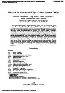
Airbus flight control system ●
The organisation of the Airbus A330/340 flight control system
Conventional aircraft control systems rely on mechanical and hydraulic links between the aircraft’s controls and the flight surfaces on the wings and tail. The controls and flight surfaces are directly connected. Mechanical links are also used for the engine control. In fly-by-wire systems, the cockpit controls generate electronic signals that are interpreted by a computer system and are then converted into outputs that drive the hydraulic system connected to the flight surfaces. Engine control is also mediated by the FCS computers.
The fly-by-wire system provides a more usable interface and takes over some computations that previously would have to be carried out by the pilots. By mediating the control commands, the system can ensure that the pilot cannot put the aircraft into a state that stresses the airframe or stalls the aircraft.
Weight reduction •
By reducing the mechanical linkages, a significant amount of weight (and hence fuel) is saved.
Fly-by-wire systems must be fault tolerant as there is no ‘fail-safe’ state when the aircraft is in operation. In the Airbus, this is achieved by replicating sensors, computers and actuators and providing ‘graceful degradation’ in the event of a system failure. In a degraded state, essential facilities remain available allowing the pilot to fly and land the plane.
Backup systems for the flight control computers. Control switches automatically to these systems if the primary computers are unavailable.
Only one computer is required for flight control. •
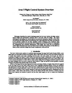
●
Responsible for calculations concerned with aircraft control and with sending signals to the actuators associated with the control surfaces and engines.
Therefore, quintuple redundancy is supported. All operational computers operate in parallel so there is no switching delay.
Two data concentrator computers •
Gather information from the flight control system and pass this to warning and display systems, flight data recorders and maintenance systems.
The primary and secondary flight control computers use different processors. The primary and secondary flight control computers are designed and supplied by different companies. The processor chips for the different computers are supplied by different manufacturers. All of this reduces the probability of common errors in the hardware causing system failure.
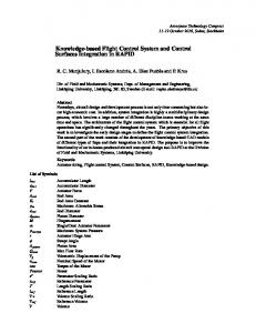
The command unit and the monitor unit are separate channels within a single computer. Each channel has separate hardware and different software. If the results of the channels disagree (as checked by the comparator) or are not produced at the same time then an error is assumed and control switches to another machine.
The software for the different channels in each computer has been developed by different teams using different programming languages. The software for the primary and secondary flight control computers has been developed by different teams. For the secondary computers, different languages are again used for the different channels in each machine.
The FCS may be reconfigured dynamically to cope with a loss of system resources. Dynamic reconfiguration involves switching to alternative control software while maintaining system availability. Three operational modes are supported • • •
●
Normal - control plus reduction of workload; Alternate - minimal computer-mediated control; Direct - no computer-mediation of pilot commands.
At least 2 failures must occur before normal operation is lost.
The linkages between the flight control computers and the flight surfaces are arranged so that each surface is controlled by multiple independent actuators. Each actuator is controlled by different computers so loss of a single actuator or computer will not mean loss of control of that surface. The hydraulic system is 3-way replicated and these take different routes through the plane.
There have been a number of Airbus accidents that may be related to problems with the FCS. One accident (Warsaw runway overrun) has been clearly identified as a problem with the specification and not with the system itself. There is no evidence of any failures of the FCS hardware or software. However, the pilots may misinterpret how the system operates and hence make errors that it can’t cope with. Most likely when the system was newly introduced.