Department of Production Engineering & Metallurgy. Effect of Germanium ,Tellurium and Cerium Additions and Thermo-Mechanical Treatment on Properties of ...
The Republic of Iraq Ministry of Higher Education & Scientific Research University of Technology Department of Production Engineering & Metallurgy
Effect of Germanium ,Tellurium and Cerium Additions and Thermo-Mechanical Treatment on Properties of CuAl- Ni Shape Memory Alloys
A Thesis submitted to the Department of Production Engineering and Metallurgy University of Technology in Partial fulfillment of the requirement for a Doctor of Philosophy in Engineering Metallurgy by
Raad Suhail Ahmed Adnan Hafidh B.Sc, M.Sc,
Supervised By Prof. Dr. Muna Khethier Abbass
Asst.Prof. Dr. MuntherMohammed Al-Kubaisy
2016
بسن اهلل الزمحن الزحين اقزا بسن ربك الذي خلق االنسان هن علق االكزم
3
2
1
خلق
أقزا و ربك
الذي علن بالقلن
علن االنسان هامل يعلن صدق اهلل العظين سورة العلق اآليات 5-1
4
5
After Thanking the Almighty god and praying on his Messenger Mohammed (GPOH) ,it is my duty to thank both my supervisors Prof. Dr.Muna Kheither Abbass and Asst. Prof. Dr. Munther MohmmedRadhy for all their support that they gave to me , also the head of the Production Engineering & Metallurgy Department Asst. Prof.Dr Ahmed Ali Akbar Akbar, I would like to thank the head of the Materials engineering department andthe Scientific Deputy of the Department for all the help they gave alsothe engineering staff of both departments, the staff of the TurningUnit at the Workshops and Training department especiallyfor help, and the staff of the Nano And Advanced Materials Center, andalso to whom I forgot to mention my sincere apologies to them
Raad.S.AA.Hafidh
Abstract The aim of this thesis is to study the effect of Ge ,Te and Ce and thermo-mechanical treatment on the properties of Cu-Based SMA . It has wide range of application such as valves actuators
and military
applications due to their low cost and economic properties compared to the other alloys .In this study the (Cu-14%Al-4.5%Ni) SMA was selected as base alloy in the first stage the base alloy was modified with alloying elements (Ge, Ce, Te) in three different percentages of (0.3,1,3)% for each element were prepared by casting in vacuum induction furnace with passing Ar gas. Homogenizing was carried out at 900 ◦C and then rapid cooling in brine solution (H2O+10% NaCl) treatment .Chemical composition analysis and XRD analysis were made to the base and modified alloys to identify the main phases in base alloy and modified alloys these phases are needle shape martensite (β`) and
stack pile
martensite (γ`) .Shape memory effect was studied by DSC test to calculate transformation temperature
martensitic and austenitic
transformation . and recovery strain test were carried out also Vickers micro-hardness test and also compression test was performed on all prepared SMA to determine the modulus of elasticity and the yield point to find a suitable load which can be applied during thermomechanical process .In the second phase thermo mechanical process was applied to all SMA alloy by applying uniaxial compression load of 30 KN to a cylindrical specimen with using graphite as lubricant at three different temperatures of (260◦C, 280◦C,300◦C) in a heat unit were contains a steel die a piston covered stone wool as insulator between it and Instron unit recovery strain were calculated .The result showed that the SMA modified with Ge addition especially with 3% Ge these alloys enhanced the strain and yield stress and shape memory properties which became outside the domain about 250 ◦C .While the SMA modified with Te addition showed less improvement in strain and yield stress and shape
memory effect particularly the shape memory properties were outside the domain as observed in DSC up to 233◦C . The modified alloys with Ce addition showed less improvement in strain and yield in mechanical alloy and shape memory effect more than alloys modified with Te and Ge . The thermomechanical treatment (TMT) results showed the base alloy gave a change in mechanical properties at 260 ◦C and the modified alloys gave a better improvement in mechanical properties at 280 ◦C and also in transformation temperature but at 260◦C and 300◦C showed less improvement for the modified alloys. Transformation temperature remained in domain as observed in DSC (-100 170) with the except for 300 ◦C which gave improvement, which showed improvement in transformation temperature which became outside the domain observed in DSC.
List of Contents
Page No.
Chapter One Introduction 1-1
Overview
2
1-2 1-3 1-4 1-5 1-6
The commercial Shape Memory Alloys Application of Shape Memory Alloys Advantages and disadvantages of Cu-Al-Ni SMA The Aim of this work Thesis outline Chapter Two Theoretical Background Introduction Shape memory effect General Characteristics One Way Memory Effect Two way shape Memory Effect Super Elasticity Measuring The Shape Memory Effect Differential Scanning Calorimeter Types of shape memory alloys Cu-Based Shape Memory Alloys Cu-Zn-Al Shape Memory Alloys Cu-Al-Be Shape Memory Alloys Cu-Al-Ni Shape Memory Alloys Manufacturing Techniques of Shape Memory Alloys Production of Cu-Based SMA Martensitic Transformations Crystallography of Shape Memory Alloys Thermomechanical Characterization & Processing of SMA Effect of Alloying Element on SMA High Temperature Shape memory alloy Thermo Mechanical Process Thermo Mechanical Process for Cu-Based SMA Thermo-Mechanical Mathematical Model for Cu-Al-Ni Alloy The Selection of the Shape Memory Alloy
2 3 4 5 6
2-1 2-1 2-2 2-2-1 2-2-2 2-3 2-4 2-4-1 2-5 2-6 2-6-1 2-6-2 2-6-3 2-7 2-8 2-9 2-10 2-11 2-12 2-13 2-14 2-15 2-16 2.16
iii
8 8 9 10 10 11 13 14 17 17 17 18 18 21 22 23 25 27 30 32 33 33 34 37
3-1 3-2 3-3 3-4 4-1 4-2 4-3 4-3-1 4-3-2 4-4 4-5 4-6 4-7 4-8 4-8-1 4-8-2 4-8-3 4-8-4 4-8-5 4-8-6 4-8-7 5-1 5-2 5-2-1 5-2-2 5-2-3 5-2-4 5-3 5-3-1 5-3-2 5-3-3 5-3-4 5-4
Chapter Three : Literature Survey Introduction Modification of SMA Thermo-Mechanical Processing Summary and conclusions Chapter Four Experimental Work Introduction The used materials Preparation of Shape Memory Alloys Preparation of SMA base alloy Adding the elements to SMA Chemical Composition Categorization of the specimens Homogenization Machining Inspections and tests XRD Differential Scanning Calorimetry DSC Compression test Hardness test Thermo Mechanical treatment Scanning Electron Microscopy –Electron Dispersion Spectrum Optical Microscope Chapter Five : Results and Discussion Introduction Microstructure of base alloy and modified alloys SMA Microstructure examination of base SMA Microstructure of G group Alloys (Containing Ge) Microstructure of T group Alloys (Containing Te) Microstructure of C Group Alloys (containing Ce) XRD Analysis XRD patterns for Base SMA XRD Patterns for G Group Alloys (Containing Ge) XRD Patterns for T Group Alloys (Containing Te) XRD Patterns for C Group Alloys (Containing Ce) DSC Thermogram iv
39 39 43 48 50 52 52 53 53 55 55 56 56 58 58 58 59 60 61 61 62 64 64 64 66 69 72 74 74 75 78 80 82
5-4-1 5-4-2 5-4-3 5-4-4 5-5 5-5-1 5-5-2 5-5-3 5-5-4 5-6 5-6-1 5-6-2 5-6-3 5-6-4 5-7 5-7-1 5-7-2 5-7-3 5-7-4 5-8 5-8-1 5-8-2 5-8-3 5-8-4 5-9 5-9-1 5-9-2 5-9-3 5-9-4 5-10 5-10-1 5-10-2 5-10-3
DSC Thermogram of base SMA DSC Thermogram of G Group Alloys (Containing Ge) DSC Thermogram of T Group Alloys (Containing Te) DSC Thermogram of C Group Alloys (Containing Ce) Shape Memory effect Shape Memory Effect of Base SMA Shape Memory Effect of SMA with Ge Addition Shape Memory Effect of SMA with Te Addition Shape Memory Effect of SMA with Ce Addition Compression Test Results Compression Test Results Of Base SMA Compression Test Results Of SMA With Ge Addition Compression Test Results Of SMA With Te Addition Compression Test Results Of SMA With Ce Addition Hardness Test Results Hardness Test Results of Base SMA Hardness Test Results of SMA with Ge Addition Hardness Test Results of SMA with Te Addition Hardness Test Results of SMA with Ce Addition Thermo-Mechanical Treatment Results for Base Alloy Microstructure and SEM Image DSC Thermogram Shape Memory Effect Thermo –mechanical treatment effect on Hardness Thermo-Mechanical Treatment Results for SMA with Ge Addition Microstructure and SEM Image DSC Thermogram Thermo –mechanical treatment effect on Shape Memory Effect Thermo –mechanical treatment effect on Hardness Thermo-Mechanical Treatment Results for SMA with Te Addition Microstructure and SEM Image DSC Thermogram Thermo –mechanical treatment effect on Shape v
82 83 86 90 92 93 94 95 97 99 99 100 102 103 105 105 105 106 107 108 108 112 114 116 116 117 123 130 134 135 135 141 147
5-10-4 5-11 5-11-1 5-11-2 5-11-3 5-11-4 6-1 6-2 6-3
Memory Effect Thermo –mechanical treatment effect on Hardness Thermo-Mechanical Treatment Results for SMA with Ce Addition Microstructure and SEM Image DSC Thermogram Thermo –mechanical treatment effect on Shape Memory Effect Thermo –mechanical treatment effect on Hardness Chapter Six: Conclusion and recommendations Introduction Conclusions Recommendation References Appendix A Appendix B Appendix C Appendix D Appendix E
vi
150 151 151 165 162 165 168 168 171 173 174 175 180 183 200
List of Figures Figure No. 1-1
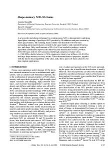
Caption Shape Memory Alloy Application in Aviation
Page 3
1-2
SMA Actuators
4
2-1
the mechanism of the SME
9
2-2
One way memory shape
10
2-3
Two way memory shape
11
2-4
Super elasticity
12
2-5
Standard DSC thermogram for SMA
15
2-6
18
2-8
the influence of the beryllium and aluminum content on the Ms Temperature the position of the β domain for Cu-Al alloys with 4% of nickel Schematic of Manufacturing SMA
2-9
Schematic of the austenite Martensite interface
26
2-10
example of constant temperature phenomenological transformation behavior in SMA Experimental Example of a Constant-Temperature Phenomenological Transformation Behavior in SMA at Multiple Temperatures (T) The solution of the mathematical Model flowchart of the experimental work The electrical Furnace the die and the Mixer SMA Casting EDM Wire Cutting Machine DSC Device Instron wdw-200
28
2-7
2-11
2-12 4-1 4-2 4-3 4-4 4-5 4-6 4-7
vii
19 21
29
36 51 53 54 54 56 58 59
4-8
A standard E-9 Specimen of SMA before and after Compression test
60
4-9 5-1
61 64
5-10
The Thermo-mechanical System Showing microstructure of base shape memory alloy A:optical image at magnification X600B: SEM Image Microstructure analysis of base alloy SMA EDS analysis for base alloy SMA Showing the microstructure of SMA+0.3%Ge A:optical Image at X600B: SEM Image Showing the microstructure of SMA+1%Ge A:optical Image at Magnification= X800 B: SEM Image Showing microstructure of SMA+ 3%Ge A:optical Image at Magnification=X400,B: SEM Image Showing microstructure of modified shape memory alloy with 0.3% Te A:optical image at X400B: SEM Image Showing microstructure of modified Shape memory alloy with 1% Te optical Image at X600 Microstructure of modified shape memory alloy with 3% Te A:optical Image at 400 XB: SEM Image SMA modified with 3%Te EDS results
5-11
SEM Image of alloy modified with 3%Te
71
5-12
Showing microstructure of modified shape memory alloy with 0.3% Ce, A:optical microstructure at 400XB: SEM Image Showing microstructure of modified shape memory alloy with 1% Ce: optical Image Magnification =X400 Showing microstructure of modified shape memory alloy with 3% Ce A:optical Image at 400XB: SEM Image XRD Pattern For SMA base alloy
72
5-2 5-3 5-4 5-5
5-6 5-7
5-8 5-9
5-13
5-14
5-15
viii
65 65 66 67
68 69
70 70
71
73
74
75
76 76 77 78 78 79 81 81 82 83 84
5-36
XRD pattern for SMA modified with 0.3%Ge XRD pattern for SMA modified with 1%Ge XRD pattern for SMA modified with 3%Ge XRD pattern for SMA modified with 0.3%Te XRD pattern for SMA modified with 1% Te XRD pattern for SMA modified with 3% Te XRD pattern for SMA modified with 0.3%Ce XRD pattern for SMA modified with 1% Ce XRD pattern for SMA modified with 3% Ce DSC thermogram for base Alloy ( rate=10 ◦C/min) DSC thermogram for SMA Modified 0.3% Ge ( rate=10 ◦C/min) DSC thermogram for SMA Modified 1% Ge ( rate=10 ◦C/min) DSC thermogram for SMA Modified 3% Ge ( rate=10 ◦C/min) DSC thermogram for SMA Modified 0.3% Te ( rate=10 ◦C/min) DSC thermogram for SMA Modified 1% Te ( rate=10 ◦C/min) DSC thermogram for SMA Modified 3% Te ( rate=10 ◦C/min) DSC thermogram for SMA Modified 0.3% Ce ( rate=10 ◦C/min) DSC thermogram for SMA Modified 1% Ce ( rate=10 ◦C/min) DSC thermogram for SMA Modified 3% Ce ( rate=10 ◦C/min) Thermo-Mechanical Characterization for base SMA Shape memory effect test of G group SMA
5-37
Shape memory effect test of T group alloys.
96
5-38
Shape memory effect test of C group alloys.
98
5-39
Stress –Strain Curve for Base SMA
100
5-16 5-17 5-18 5-19 5-20 5-21 5-22 5-23 5-24 5-25 5-26 5-27 5-28 5-29 5-30 5-31 5-32 5-33 5-34 5-35
ix
84 85 88 88 89 91 91 92 93 94
5-40 5-41 5-42 5-43
Stress-Strain Curve SMA modified with Ge Stress-Strain Curve SMA modified with Te Stress-Strain Curve SMA modified with Ce Hardness results of SMA modified with Ge
101 103 104 106
5-44
Hardness results of SMA modified with Te
107
5-45
Hardness results of SMA modified with Ce
108
5-46
Showing the Microstructure of base after TMT at 260◦C For A:Optical Image at X200 and B: SEM Image Showing the microstructure for of the base alloy after TMT at 280◦CA:Optical Image atX200 and B: SEM Image Showing microstructure of the base alloy after TMT at 300◦C A:Optical Image at=200X and B: SEM Image SEM-EDS For Base Alloy After TMT at 280◦C
109
5-50 5-51
EDS analysis for base alloys Thermogram for the base alloy (Cu-14%Al4.5%Ni) after TMT at 260 ◦C (rate=10◦C)
111 112
5-52
Thermogram for the base alloy (Cu-14%Al-4.5%Ni ) after TMT at 200 ◦C (rate=10◦C)
113
5-53
Thermogram for the base alloy (Cu-14%Al4.5%Ni) after TMT at 300 ◦C (rate=10◦C)
113
5-54 5-55 5-56
Stress –strain curve for base SMA &after TMT Hardness results of base alloy after TMT Showing microstructure of SMA with 0.3% Ge after TMT at 260 ◦C A optical image X200 and SEM Image Showing the microstructure SMA modified with 0.3% Ge after TMT 280 ◦C Optical image at X200 and SEM Image
115 116 117
5-47
5-48
5-49
5-57
x
109
110
111
118
5-58
Showing the microstructure of SMA Modified
118
0.3% Ge after TMT at 300 ◦C A The optical image X200 and B SEM Image 5-59 5-60
Showing microstructure of SMA modified 1 % Ge at 260 ◦C, 400X Showing microstructure of SMA modified with1%
119 119
Ge at 280 ◦C,400X 5-61
Showing microstructure of SMA modified with 1%
120
Ge after TMT at 300 ◦C, X400 5-62
Showing microstructure of SMA with 3% Ge after
121
TMT at 260 ◦C A Optical Image at 200X and B SEM Image 5-63
Showing microstructure SMA modified with 3%
122
Ge after TMT at 280◦C A optical ImageX200B SEM Image Showing microstructure of SMA modified with 3% Ge after TMT at 300 ◦C (A)SEM Image and (B) optical Image (Magnification=200) Thermogram for the G1 Alloy after TMT at 260 ◦C(rate =10◦C/min)
123
5-66
Thermogram for the G1 Alloy after TMT at 280 ◦C(rate =10◦C/min)
126
5-67
Thermogram for the G1 Alloy after TMT at 300 ◦C(rate =10◦C/min)
126
5-68
Thermogram for the G2 Alloy after TMT at 260 ◦C(rate =10◦C/min)
127
5-69
Thermogram for the G2 Alloy after TMT at 280 ◦C(rate =10◦C/min)
128
5-64
5-65
xi
125
5-70
Thermogram for the G2 Alloy after TMT at 300 ◦C(rate =10◦C/min)
128
5-71
Thermogram for the G3 Alloy after TMT at 260 ◦C(rate =10◦C/min)
129
5-72
Thermogram for the G3 Alloy after TMT at 280 ◦C(rate =10◦C/min)
130
5-73
Thermogram for the G3 Alloy after TMT at 300 ◦C(rate =10◦C/min)
130
5-74 5-75
SME of the G Group alloys after TMT at 260 ◦C SME of the G Group alloys after TMT at 280◦C
132 132
5-76
SME of the G Group Alloys after TMT at 300◦C
133
5-77
Effect of thermo mechanical treatment on hardness
134
5-78
showing the microstructure of SMA Modified 0.3% Te at 260 ◦C (A) optical image at X400 (B) SEM Image showing the microstructure of SMA Modified 0.3% Te at 280 ◦C (A) optical image at X400 (B) SEM Image showing the microstructure of SMA Modified 0.3% Te at 300 ◦C (A) optical image at X400 (B) SEM Image Showing the microstructure of SMA modified with
136
5-79
5-80
5-81
136
137
137
1% Te after TMT at t 260 ◦C, with 1% Te at 260 ◦C ,X400 5-82 5-83 5-84
Showing microstructure of SMA modified with 1% Te at 280 ◦C,X800 Showing the microstructure (Magnification=X800) of SMA modified with 1% Te at 300 ◦C ,X800 showing the microstructure of SMA +3% Te at 260 xii
138 138 139
◦C TMT (A) optical image at X400 (B) SEM Image 5-85
showing the microstructure of SMA +3% Te at 300 ◦C TMT (A) optical image at X400 (B) SEM Image
139
5-86
showing the microstructure of SMA +3% Te at 300 ◦C TMT (A) optical image at X400 (B) SEM Image
139
5-87
EDS analysis of SMA Modified by 3% Te at 300◦C TMT Microstructure-EDS analysis for SMA modified 3% Te at 300◦C TMT Shows the thermogram for the T1 Alloy after TMT at 260 ◦C(rate =10◦C/min)
140
5-90
Shows the thermogram for the T1 Alloy after TMT at 280 ◦C(rate =10◦C/min)
142
5-91
Shows the thermogram for the T1 Alloy after TMT at 300 ◦C(rate =10◦C/min)
143
5-92
Shows the thermogram for the T2 Alloy after TMT at 260 ◦C(rate =10◦C/min)
143
5-93
Shows the Thermogram for the T2 Alloy after TMT at 280 ◦C(rate =10◦C/min)
144
5-94
Shows the Thermogram for the T2 Alloy after TMT at 300 ◦C(rate =10◦C/min)
144
5-95
Shows the Thermogram for the T3 Alloy after TMT at 260 ◦C(rate =10◦C/min) Shows the Thermogram for the T3 Alloy after TMT at 280 ◦C(rate =10◦C/min)
145
5-97
Shows the Thermogram for the T3 Alloy after TMT at 300 ◦C(rate =10◦C/min)
146
5-98
SME for T1 alloys after TMT at 260 ◦C, 280 ◦C and
148
5-88 5-89
5-96
xiii
140 142
145
5-99 5-100 5-101 5-102
5-103
5-104
5-105 5-106
300 ◦C Respectively SME for T2 alloys after TMT at 260 ◦C, 280 ◦C and 300 ◦C Respectively SME for T3 alloys after TMT at 260 ◦C, 280 ◦C and 300 ◦C Respectively Effect of Thermo mechanical treatment on hardness showing the microstructure (A)optical image at X400 and (B) SEM Image of SMA +0.3% Ce after TMT at 260 ◦C showing the microstructure(A) optical image at 400X (B) SEM Image of SMA +0.3% Ce after TMT at 280 ◦C showing the microstructure of) (A) optical image at 400X (B) SEM Image SMA +0.3% Ce after TMT at 300 ◦C Showing the microstructure C2 Alloy after TMT at 260◦C,X 400 Showing Microstructure of C2 Alloy after TMT at
149 149 150 152
152
153
153 154
280◦C, X400 5-107
Showing the microstructure of C2 Alloy after TMT
154
at 300◦C, X400 showing the microstructure of C1 alloy after TMT at 260 ◦C A optical image at X400 B SEM Image showing the microstructure of C3alloy after TMT at 280 ◦C (A) optical image at X400B SEM Image
155
5-110
showing the microstructure of C3alloy after TMT at 280 ◦C (A) optical image at X400B SEM Image
156
5-111
shows the Thermogram for the C1 Alloy after TMT at 260 ◦C(rate =10◦C/min)
158
5-112
shows the Thermogram for the C1 Alloy after TMT at 280 ◦C(rate =10◦C/min)
158
5-113
shows the Thermogram for the C1 Alloy after TMT at 300 ◦C(rate =10◦C/min)
159
5-108 5-109
xiv
155
5-114
shows the Thermogram for the C2 Alloy after TMT at 260 ◦C(rate =10◦C/min)
159
5-115
shows the Thermogram for the C2 Alloy after TMT at 280 ◦C(rate =10◦C/min)
160
5-116
shows the Thermogram for the C2 Alloy after TMT at 300 ◦C(rate =10◦C/min)
160
5-117
shows the Thermogram for the C3 Alloy after TMT at 260 ◦C(rate =10◦C/min)
161
5-118
shows the Thermogram for the C3 Alloy after TMT at 280 ◦C(rate =10◦C/min)
161
5-119
shows the Thermogram for the C2 Alloy after TMT at 300 ◦C(rate =10◦C/min)
162
5-120
SME of the C Group Alloys After TMT at 260◦C
163
5-121
SME of the C Group Alloys After TMT at 280◦C
164
5-122
SME of the C Group Alloys After TMT at 300◦C
165
5-123
Effect of Thermo Mechanical treatment on hardness
166
of SMA with Ce A-1 A-2 A-3 D-1 D-2 D-3 D-4 D-5
Cu-Ce phase diagram Cu-Ge phase diagram Cu-Te phase diagram Particle size analyzer XRD Device Shimdzoo 7000 Calistio processing output Microsoft Excel Output VEGA Scanning Electron Microscope
xv
184 184 185 197 198 200 200 201
List of Tables Table No. 2-1
Caption Properties of Cu-14%Al-4.5%Ni SMA
Page 37
4-1
Materials properties & characterization
52
4-2
Weight percentage for bulk casting
53
4-3 4-4 4-5 5-1
Chemical composition of base SMA Categorization of the prepared alloy EDM machine specification Transformation temperatures for Base SMA
55 55 57 83
5-2
Transformation temperature for SMA with Ge
86
5-3
Transformation temperature for SMA with Te
87
5-4 5-5
Transformation temperatures for alloys contain Ce Thermo-mechanical properties for SMA
90 93
5-6 5-7
Shape memory properties of G alloys Group Shape memory properties for alloys modified with Te Shape memory effect properties for alloys modified by Ce Mechanical Properties For SMA Mechanical Properties for SMA Modified with Ge Mechanical Properties for SMA Modified with Te Mechanical Properties for SMA Modified with Ce Hardness For Base SMA The Transformation temperature of SMA Base before and after thermo-mechanical treatment Shape memory properties for base alloy Transformation temperature and equilibrium temperature For SMA Modified by Ge after thermomechanical treatment Shape memory effect properties for SMA Modified by Ge after thermomechanical treatment
95 96
5-8 5-9 5-10 5-11 5-12 5-13 5-14 5-15 5-16
5-17
xvi
98 99 100 102 104 105 112 114 124
131
5-18
5-19 5-20
5-21 A-1 B-1 B-2 B-3 B-4 B-5 B-6 B-7 B-8 B-9 B-10 C-1 C-2 C-3 C-4 D-1 D-2 D-3 D-4
Transformation temperature and equilibrium temperature For SMA Modified by Te after thermomechanical treatment Shape memory effect properties for SMA Modified by Te after thermomechanical treatment Transformation temperature and equilibrium temperature For SMA Modified by Ce after thermomechanical treatment Shape memory effect properties for SMA Modified by Ce after thermomechanical treatment Physical properties and mechanical properties for the added materials XRD results for the base SMA XRD results for the SMA Modified with 0.3% Ge XRD results for the SMA Modified with 1% Ge
141
XRD results for the SMA Modified with 3% Ge XRD results for the SMA Modified with 0.3% Ce XRD results for the SMA Modified with 1% Ce XRD results for the SMA Modified with. 3% Ce XRD results for the SMA Modified with 0.3% Te XRD results for the SMA Modified with 1% Te XRD results for the SMA Modified with 3% Te The particle size distribution analysis for (Ge) The particle size distribution analysis for (Ce) The particle size distribution analysis for (Te) The particle size distribution analysis for (Ni) Nano Brook 90Plus Particle size analyzer Specification Speciation of XRD Device Speciation of DSC Device Tescan Vega easy probe SEM specifications
189 190 190 191 191 192 192 194 194 195 195 197
xvii
147 157
163 183 187 188 189
198 199 201
List of symbols and Abbreviations Symbol
Meaning
SMA SME MT SE XRD DSC SEM EDS EDM As
Shape Memory Alloy Shape Memory Effect Martensite transformation Super Elasticity X-Ray Diffraction Diffractional Scanning Coloratmry Scanning Electron microscope Energy Dispersive spectrometer Electrical Discharge Machining Austenitic Transformation Starting Temperature Austenitic Transformation Finishing Temperature Martensite Transformation Starting Temperature Martensite Transformation Finishing Temperature Thermo-Mechanical Treatment Martensite Phase (needle shape) Martensite Phase (stack pile shape) Austenite Phase Optical Microscope Equilibrium Temperature Field Emission Scanning Electron Microscope Hysteresis Spread Atomic Force Microscopy Field Emission Electron Dispersion Sepcertmoy Dynamic Mechanical Analysis Transmission Electron Microscope
Af Ms Mf TMT β` γ` β OM T◦ FESEM H S AFM FEEDS DMA TEM
Unit
◦
C
◦
C
◦
C
◦
C
◦
C
◦
C C
◦
Chapter One Introduction
Chapter One : Introduction Introduction
1.1 Overview Shape Memory Alloys(SMA) are alloys that display the capacity to hold it 's unique shape after a connected load is gone , this effect is known as the shape memory effect (SME) , it is a one of a kind property for certain combinations showing martensitic change despite the fact that the alloy is twisted at low temperature phase[1], the shape memory compound was watched firstly in 1932 by Chang and Read for an Au-Cd Alloy then in 1939 the watched this change in a Brass Bar . The converse martensitic change was presented in 1949 by Kurdjumov and Khandros taking into account test perception of the thermally reversible martensitic structure in Cu based composites by 1953 the complete thermo-versatile martensitic change was seen in different compounds, for example, In-Tl alloy[2]since the utilitarian application of SMA in restorative innovation felid considered the achievement for the SMA , the materials prescient was all the more clear with the utilization of thermo-mechanical treatment and ecological Parameters[3].
1.2 The Commercial Shape Memory Alloys In spite of developing rundown of alloys that show shape memory effect just two type of alloys have accomplished any level of applications These are NiTi (nickel–titanium) and copper–based alloys. Properties of both alloys are very distinctive. The NiTi compounds have more prominent shape memory strain (up to 8 % againstup to 6% for the copper–based combinations), have a tendency to be a great deal all the more thermally stable ,have incredible consumption resistance and have much higher
2
Chapter One : Introduction ductility. Then again, the copper–based composites are a great deal less costly, show higher activation temperatures (roughly in the extent - 200 to +200°C) than NiTi alloys and are once in a while the main decision for applications at high temperature (i.e. above 100 °C). Unfortunately, these copper–based combinations have a tendency to experience the ill effects of low quality and poor consumption resistance [3]
1.3Application of Shape Memory Alloys 1. Aviation Industry using shape-memory alloy that reduces aircraft's engine noise as shown in figure 1-1 [2]
Figure 1-1 Shape Memory Alloy Application in Aviation[2]
2.Pipingoil line pipes for industrial applications, water pipes and similar types of piping for consumer/commercial applications as shown in figure(12)
3
Chapter One : Introduction
Figure 1-2 SMA Actuators [3]
3.Automotive an automotive valve application build to run low pressure pneumatics /bladders in a car seat to adjust the contour 4.Tele communication Autofocus actuator for a smart phone. 5.Robotics There have also been limited studies on using these materials in robotics 6.Optometry Eyeglass frames made from titanium-containing SMAs are marketed under the trademarks flex on and TITAN flex[7]
1.4Advantages and Disadvantages of Cu-Al-Ni SMA 1.Good corrosion resistance compared with other Cu-based SMAs such as (Cu-Al-Zn) SMA . 2.Low cost compared with NiTi SMA. 3. Transformation Temperature(-100-170) range is more than the NiTi SMA. 4.Hysteresis and spread compared are more than other Cu-based SMAs. 5.Higher transformation domain compared with NiTi SMA.[9]
4
Chapter One : Introduction While the disadvantages are 1.Very brittle. 2.Biocompatiblity is bad. 3.Low damping compared with other Cu-based SMAs.[9]
1.5The Aim of This Work One of the problems with Cu-Al-Ni shape memory alloys is not a high temperature shape memory alloy (HTSMA) ,another problem also the brittleness of the alloy is a limitation for some applications so improving the transformation temperature domain and reducing brittleness so this thesis has an objective is to reduce brittleness and increasing the domain be applying the following steps. 1-Studying the effect of (Ge ,Te and Ce ) additions with different percentages(0.3,1,3) wt. % for a Cu-14%Al-4.5%Ni Shape memory alloy by on transformation temperatures, recovery strain and martinsite characteristics 2- Studying the effect of thermo-mechanical processing and heat treatment on microstructure by performing compression test at different deformation temperatures and fixed applied stress. 3-Studying the combined effect of added elements and thermo-mechanical treatment on microstructure, mechanical properties effect of a Cu-based alloys .
5
and shape memory
Chapter One : Introduction 1.6Thesis Outline The outline of this thesis consists of six chapters 1.Chapter one : as mentioned shows a historical brief and the objective of this work. 2 .Chapter two: deals with the theoretical consideration of the designated alloy, the properties , the applications of SMA , the elaboration of the alloy types of SMA ,Thermomechanical characterization of the shape memory alloys ,the SME. 3.Chapter three :introduce a literature survey which deals with papers investigating either thermomechanical treatment or modification of SMA 4.Chapter four : Explain and discuss the main steps of the experimental work in this study 5. Chapter five :Includes s the results of the work and the discusses of the effect of alloying element addition and the thermo-Mechanical treatment on mechanical properties ,microstructure and the shape memory effect. 6.Chapter Six : gives conclusions & recommendations for future studies in this field .
6
Chapter Two Theoretical Background
Chapter Two : Theoretical Background Chapter Two Theoretical Background 2.1 Introduction Shape memory alloys (SMAs) are smart materials that can undergo martensite phase transformation when thermo-mechanical loads applied are able to recover their original shape when heated above a certain temperature .The martensite transformation that occurs for austenite ↔ martensite is the main feature responsible for characteristic of SMAs e.g.shape memory effect and pseudo elasticity .Many alloys are subjected to these transformations such as NiTi and Cu-based alloys and Fe-based alloys .
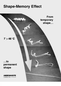
2.2 Shape Memory Effect Figure 2.1 illustrates the mechanism of the SME. In this case, a piece of SMA (for example, a wire) is in martinsite phase at room temperature and it‟s martensitic transformation temperature is sufficiently above room temperature[8].The wire can be easily bent since the martensite phase can be easily deformed by twinning or de-twinning. The deformation can be seen as a change in the fraction of the variants. If the materials are heated the bent wire to a temperature above Austenite Finish(Af) , the martensite transforms back to austenite and the sample regains its original straight shape. This is possible because all of the variants were originally formed from a single austenite crystal. On cooling to room temperature the wire re-transforms to martensite, but its shape does not change due to the self-accommodated structures. This is the mechanism of the SME.[8]
7
Chapter Two : Theoretical Background
Figure 2.1The mechanism of the SME[8]
The strain recovered by the reverse transformation can be as great as 8% whilst the recovery stress can be as large as several hundred MPa in the case of TiNi. This leads to an energy density as high as 107 J/m 3 which is three orders of magnitude higher than those of other actuator materials, such as piezo-ceramics or magneto-strictive materials. It should be emphasized that the shape change caused by the SME occurs only upon heating, and this is referred to as the one-way SME. In order to obtain a shape change upon cooling, it is necessary to control the arrangement of the variants that form on cooling from Af to room temperature[8].
2.2 General Characteristics The martensitic transformation that occurs in the shape memory alloys yields a thermo-elastic martensite and develop from a high temperature austenite phase with a long range order [9]. There are two types of shape memory effect:-
8
Chapter Two : Theoretical Background 2.2.1 One Way Memory Effect :If an alloy is deformed by applying mechanical load and then unloaded remains deformed if the alloy is then related to a temperature above the austenite finish temperature (Af) it recover the original macroscopic shape as long as the total strain does not induce permanent plastic flow as shown in figure (2-2) this is known as the hot shape[3]
Figure 2-2One way memory shape[3]
2.2.2 Two way Memory Effect:Shape memory alloy can retain to remember both endothermic and exothermic shape they can be cycled between two shapes without the need to a external stress as shown in figure (2-3)[3].Two shape memory change relay entirely on microstructural change during martensitic transformation which occur under
the influence of the
internal stress Internal stress may be introduced in a number of ways it must be stable on thermal cycling load through the transformation after each loading and unloading a small residual strain so the alloy must be trained two of the most common training methods are :
01
Chapter Two : Theoretical Background 1.Cyclic deformation at a temperature below Mf followed by constructed heating in the cold shape to above the Af temperature 2. Cyclic deformation between the hot and cold shapes at temperature above Af [4]
Figure (2-3)Two way memory shape[3]
2.3Super Elasticity The SMEs described above require temperature changes. In contrast, the super elastic effect is isothermal in nature and involves the storage of potential energy. In particular, SMA super elastic behavior is associated with stress-induced transformation that can be induced at temperature above Af. In fact, the alloy can be elastically deformed at higherthan normal levels by applying a load in the austenitic phase. Specifically, Nitinol can elastically deform to nearly 8% strain, whereas most metals only have the ability to elastically deform to less than 1% strain. The load application induces the transformation ofaustenite in detwinned martensite. Upon unloading, the martensite phase becomes unstable and transforms back to its original austenite phase, resulting in
00
Chapter Two : Theoretical Background full strain-recovery upon the removal of load. SE is represented in the stress-strain space of Fig. 2.4.The material microstructure is initially austenitic (point 1). During loading, the critical stress for phase transition is reached (point 2) and the material transforms directly into detwinned martensite (plateau 2e3). Once the phase transition is complete, further loading only causes elastic deformation of the de-twinned martensite (slope 3e4). Austenite is the only stable phase at high temperature and no stress, therefore, during unloading the critical stress for the reverse phase transition is reached and the macroscopic deformation is recovered (plateau 5e6).Because of the presence of a small hysteresis loop between the loading and unloading plateau, this property is often referred to as SE.PE is used in many biomedical and other super elastic applications where high reversible strains have to be combined with high stress plateaus .More specifically, in the biomedical field, NiTi SMAs are successfully used in orthodontics, orthopedics, medical instruments, and endovascular applications (stents), whereas new developments are expected in bone engineering, drug delivery systems, and extra vassal scaffolding
Figure (2-4)Super elasticity[8]
01
Chapter Two : Theoretical Background
2.4 Measuring The Shape Memory Effect There
are
five
major
methods
of
characterizing
the
transformation in SMAs and a large number of minor methods that are only rarely used and will not be discussed. 1. The second method often used is to measure the resistivity of the sample as it is heated and cooled. The alloys exhibit interesting changes and peaks in the resistivity (by up to 20%) over the transformation temperature range; however, correlating these changes with measured phase changes or mechanical properties has not always been very successful. 2. The curve shown in Fig.2.4 is the direct information one obtains from this test. The values obtained for the transformation points, such as Ms and Af, from this method are offset to slightly higher temperatures from the values obtained from DSC testing. This happens because the DSC test occurs at no applied stress, and the transformation is not stress induced. 3. the stress-strain properties can be measured in a standard tensile test at a number of temperatures across the transformationtemperature range, and from the change in properties the approximate
transformation-temperature
values
can
be
interpolated. This is very imprecise, though, and is much better applied as a measure of the change in properties of each phase, due to such things as work hardening or different heat treatments. 4.
Neutron
Diffraction
Analysis
The phase transformations
described in the previous sections that are investigated via calorimetric and thermomechanical tests can also be studied using other techniques that provide information on the morphology of the
02
Chapter Two : Theoretical Background transforming phases resulting from applied external forces, primarily thermal and mechanical. One of these techniques is in situ neutron diffraction of the polycrystalline structure of SMA transforming under thermal and mechanical cycles. 5. The most direct method is by differential scanning calorimeter (DSC). This technique measures the heat absorbed or given off by a small sample of the material as it is heated and cooled through the transformation-temperature range. The sample can be very small, such as a few milligrams, and because the sample is unstressed this is not a factor in the measurement[4,9].
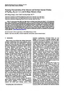
2.4.1 Differential Scanning Calorimeter Differential scanning calorimetry (DSC) testing is the most popular thermal analysis technique used to evaluate phase transformation temperatures and the latent heat related to them. It measures the difference in the amount of heat required to increase the temperature of a sample and a reference as a function of temperature. Hence, it is also widely used to measure the starting and ending temperatures of martensitic transformations .In Figure. 2.5a typical DSC thermogram of an SMA is shown, with two transformation peaks. The power required to maintain a constant heating rate for the alloy is represented on the y-axis, whereas the temperature of the chamber is reported on the x-axis.
03
Chapter Two : Theoretical Background
Figure (2-5 ) Standard DSC thermogram for SMA[11]
The endothermic peak is associated with the transformation from twinned martensite to austenite, and it stands for additional heat to be supplied to maintain the constant heating rate. This transformation is identified by two temperatures: the austenite starting temperature(As) and the austenite finishing temperature (Af). The exothermic peak represents the transformation between austenite and martensite, and it is identified by a starting temperature (Ms) and a finishing temperature (Mf), as well. All the transformation temperatures are measured by means of the tangent method. Together with the martensite and austenite phases, an intermediate phase in the cooling curve can be detected, called the R phase ,transformation temperatures can be affected strongly by the mechanical history and the mechanical energy stored by the sample, which could be responsible for precipitation, dislocation, and detaining. In these cases, the transformation peaks may be shifted in the thermogram Specifically, if the sample is strained and twinned martensite is formed, the temperatures characterizing the transformation from austenite to
04
Chapter Two : Theoretical Background martensite are shifted to greater values, because in the specimen of twinned and detwinned martensite, the shift of the DSC peak is more pronounced as the percentage of twinned martensite increases in the sample. This means that reverse-phase transition temperatures increase with increasing strain. Mechanical deformation at low temperatures induces a stabilization of the martensite phase, as demonstrated by the increase in the reverse-phase transition [10] The heat of transformation and the associated transformation temperatures are most commonly determined using the Differential Scanning Calorimeter(DSC). The DSC is a popular thermal analysis technique that can be used to measure the phase transformation temperatures, the latent heat due to transformation, and the specific heat capacity of different phases in a material. This technique is also widely used to study the transformation temperatures of SMAs and has the advantage of requiring only a small quantity of material. The principle behind the operation of the DSC is the measurement of the rate at which heat energy is supplied to a specimen to maintain a constant heating or cooling rate. ADSC operating on such a principle is called a power compensated DSC [2], Also the equilibrium temperature is calculated from equation2-1 and hysteresis from equation 2-2[10] and Spread from equation 2-3 [10] -------2-1 Hysteresis =As-Mf-------2-2 Spread =Af-As---2-3
05
Chapter Two : Theoretical Background 2.5Types of Shape Memory Alloys Although a relatively wide variety of alloys are known to exhibit the shape memory effect, only those that can recover substantial amounts of strain or that generate significant force upon changing shape are of commercial interest. the most widely used alloys are [1,7] 1. Ti-based alloys 2. Copper based alloys 3. Iron based alloys 4. High Temperature shape memory alloys (Ex: Cobalt Based Alloys) 5. Others alloys systems Ex: Au-Tl ,Ru-Nb
2.6 Cu-Based Shape Memory Alloys Although NiTi SMAs offer excellent pseudoelastic and SME properties and are biocompatible, they are relatively expensive compared to Cu-based SMAs. Good electrical and thermal conductivity along with their formability makes Cu-based SMAs an attractive alternative to NiTi. Copper-based alloys generally exhibit less hysteresis than NiTi, with the transformation temperatures in Cu-based alloys highly dependent on the composition. A precise change from10−3 to 10−4wt% is sometimes necessary to achieve reproducible transformation temperatures within a 5◦C range. The main Cu-based alloys are found in the Cu-Zn and Cu-Al systems[2]
2.6.1 Cu-Zn-Al Shape Memory Alloys The CuZn binary alloys are very ductile and have resistance to intergranular fracture as compared to other Cu-based alloys These alloys CuZnAl alloys are also very sensitive to heat treatments such that the quenching rate can lead to phase dissociation or change in transformation
06
Chapter Two : Theoretical Background temperatures. Their mechanical behavior is limited to stress levels of approximately 200 MPa due to the low critical stress for slip. Within the operational range of stress, the alloy exhibits perfect SME and pseudo elasticity, but the transformation strain is limited to about3-4%[2]
2.6.2Cu-Al-Be Shape Memory Alloy The addition of beryllium in a small proportion modifies the equilibrium diagramfor Cu-Al: the temperature of the eutectoid plateau is reduced, and above all thecurve of the transformation temperatures is brought down. The martensite formedisRubthrombic(9R). Unlike the effect of nickel, addition of beryllium in a low concentration does not affect the composition or the temperature of the TTT (time-temperaturetransformation)diagram. Figures 2.6 show the influence of the beryllium and aluminum content on the Ms Temperature.[9]
Figure (2-6)The influence of the aluminum content on the Ms Temperature.[9]
2.6.3Cu-Al-Ni Shape memory Alloy CuAlNi is less sensitive to stabilization and aging phenomena. Similar to Cu-Zn-Al, the transformation temperatures of Cu-Al-Ni can be varied by changing the aluminum or nickel content. Changing the aluminum composition between 14 at.% and 14.5 at.% can change the Ms temperature from−140 ◦C to 100 ◦C. The relative change in
07
Chapter Two : Theoretical Background transformation temperatures is not significant and the hysteresis remains fairly constant line and the curve of the phase transformation start martensite start, denoted Ms– dotted line[2]. We can see in this diagram that it is possible to obtain a martensite start temperature at ambient temperature, but the corresponding alloy with around 14%Al is very brittle. In practical terms, we can only use alloys with lower aluminumconcentrations, with a martensite start temperature of around 200°C. The additionof nickel causes a shift in the domain of stability of the β phase in relation to the transformation temperature curve without noticeably changing the rest of the diagram.[9]
Figure(2-7)Cu-Al-Ni Ternary Alloys Phase diagram[2]
the dotted curve in Figure 2.7 shows the position of the β domain for Cu-Al alloys with 4% of nickel. At this concentration of nickel, an alloy with 13.2% aluminum and4% nickel) is in the domain where the β phase is most stable with a martensite start temperature of around 150°C. We
08
Chapter Two : Theoretical Background can increase the aluminum content in order to decrease the Ms temperature to around 50°C, with 14% Al. Beyond this 14% concentration of Al, the martensite formed becomes hexagonal (2H)instead of robuithmbic (9R) , as is the case with Cu-Zn-Al that is too rich in Al), and the alloys become brittle. Hence, in practical terms, for applications, usable Cu-Al-Ni alloys cannot have Ms temperatures lower than 50°C.On the other hand, these alloys have a good resistance to high temperatures, up to around 200°C. Hence, they are well adapted for applications where the shape-memory element has to withstand high temperatures, but with a domain of function always above 50°C. [9].Nickel is adopted as a valid alternative to zinc, and cheap as well. CuAl-Ni has undergone extensive development and is usually preferred among the copper alloys. A typicall composition is made of 13% Al, 4% Ni, and Cu to balance. Transformation temperatures are in the range between 80 and 200 ◦C. As with the former compound, it is cheap and may be processed by standard methods. The mechanical characteristics may be improved by using the same additives already mentioned for CuZn-Al. Furthermore, small percentages of Mn (replacing equal quantities of Al) reduce the transformation temperatures. Extra elements can affect the stability of the alloy and
therefore their use must
be
limited.Differently from Cu-Zn-Al, the Al percentage in Cu-Al-Ni does not significantly affect workability, and hot working is the only adequate fabrication procedure. As act on sequence of hot working, these materials needs a controlled cooling process to fix important attributes such as transformation temperatures. Moreover, further treatments are usually required to stabilize those parameters. This articulated process makes thi smix more expensive than the former copper alloy, yet cheaper than NiTi. Significant aging effects are observed at temperatures higher than 120
11
Chapter Two : Theoretical Background C◦ while transformation temperature ranges are generally smaller than Cu-Zn-Al ones. [2,9,10]
2.7Manufacturing Techniques of Shape Memory Alloys Much of the SMA manufacturing and the processing literature is property and only a small part of it is published. Abroad classification of many production techniques are summarized in Fig. 2.6 The two primary manufacturing techniques can be classified under casting or powder metallurgy techniques[12].The casting techniques are popular with large scale production of NiTi alloys that generally involves melting followed by hot working and final machining The most popular commercial casting techniques are using vacuum induction melting (VIM),vacuum Arc re-melting (VAR) and electronic beam melting (EBM) techniques. Several powder metallurgy or additive manufacturing techniques have been proposed for small scale SMA component production. These techniques are mainly used by the biomedical community that involves manufacturing of porous SMA components or intricate components due to their expensive initial costs.[12]
Figure (2.8) Schematic of Manufacturing SMA[12]
10
Chapter Two : Theoretical Background 2.7Production of Cu-Based SMA The different stages of the elaboration of a copper-based shapememory alloy include the choice of raw materials, smelting, shaping and betatization treatments and reheating[6]:
2.7.1 Raw Materials In order to avoid a decrease in the properties of the alloys ,primarily due to interactions between the movement of the variants and impurities, the purity of the different components needs to be very high – greater than 99.99%.
2.7.1 Smelting The different elements of the alloy in a sufficient quantity are melted; however, before proceeding with the casting, it is crucial to very precisely monitor its composition. The martensitic transformation temperatures are very highly dependent upon the composition of the alloys. Thus, the proportion of the different elements in the alloy is extremely critical. The conventional analytical methods for this type of operations such as spark spectrometry are not accurate enough. In practical terms, a sample is taken just before casting and
this sample is subjected to thermal
betatization treatment and reheated, and then its transformation temperatures are measured. If these temperatures do not correspond to those being sought for the planned application, the composition of the bath of molten metal is corrected by the addition of metal just before casting.[6]
2.7.2 Shaping The procedures for shaping depend on the alloy which has been made. As we saw above, Cu-Zn-Al can be shaped at ambient temperature if the
11
Chapter Two : Theoretical Background alloy is in the bi-phase state (α + β). In the case of Cu-Al-Ni, shaping can only be done at a high temperature of over 600°C.[6]
2.7.3 Homogenization The martensitic transformation treatment responsible for the shapememory properties occurs from the beta phase. As this phase is not thermodynamically stable at ambient temperature, it is therefore necessary to raise the alloys to the temperature of the beta domain and then quench them in order to stabilize them in that state. The quenching is followed by a reheating in order to eliminate the quenching vacancies and stabilize the state of order of the alloy [6].
2.8 Martensitic Transformations The SME is based on a special class of solid-solid phase transformations called martensitic transformations(MT). These occur in crystalline materials between two fundamental lattice structures called austenite and martensite. Austenite forms highly symmetric unit cells which are stable at high temperature. During a MT, the austenitic lattice undergoes a shear and or a shear/shuffle type of transformation and forms martensite which has a lesser degree of symmetry. Variants of martensite exist, basically because there are different deformation modes of the austenitic lattice. Martensite is stable at low temperature, such that lattice transformations may be induced by lowering the temperature below certain
Transformation temperatures . At high temperatures, where
austenite is stable, MT may be also induced by applying external loads.[13]SMAs have two stable phases with different crystal structure and properties. The high temperature phase is called austenite or parent phase and has a body centered cubic crystal structure, whereas the lowtemperature phase is called martensite and is characterized by a lower symmetry, having a tetragonal, orthorhombic, or monoclinic crystal
12
Chapter Two : Theoretical Background structure. Thus, it can appear in a number of crystallographiclly equivalent variants, which differ in their orientation with respect to the material axes. In fact, the martensite assembly can exist in two forms: twinned and de-twinned. The twinned martensite is formed by combination of self-accommodated martensitic variants, whereas in the de-twinned martensite a specific variant is predominant. The functional properties of SMAs are closely linked to the reversible transformation from austenite to martensite. Upon cooling, in absence of loading, austenitic.[11]The transformation, although a first-order phase change, does not occur at a single temperature, but over a range of temperatures that varies with each alloy system. The usual way of characterizing the transformation and naming each point in the cycle is shown in Figure 2.4. Most of the transformation occurs over a relatively narrow temperature range, although the beginning and end of the transformation during heating or cooling actually extends over a much larger temperature range. The transformation from the austenitic phase to the martensitic phase shows a temperature and/or stress hysteresis. It follows that the temperature or stress-induced transformation cannot be characterized by a single value of temperature or stress. In fact, the temperature-induced transformation is characterized by four temperatures: Ms and Mf during cooling and As and Af during heating. Ms and Mf indicate the temperatures at which the transformation from the parent phase into martensite starts and finishes ,whereas As and Af indicate the temperatures where the reverse transformation begin and finishes, respectively. The hysteresis of transformation is of the order 10-50 ◦C in temperature.[11]
13
Chapter Two : Theoretical Background 2.9 Crystallography of Shape Memory Alloys The transformation from austenite to martensite is a diffusionless transformation that occurs by shear distortion of the lattice structure i.e. movement of atoms from their original position. This martensitic transformation possesses well-defined characteristics that distinguish it from other transformations. Within a single crystal ,the shear distortion occurs along a specific plane called the habit plane, which forms the interface between the martensitic and the austenitic phases. Since the habit plane does not rotate or deform during the course of the transformation, the plane is also referred to as the lattice invariant plane. Figure 2.9 schematically shows an austenite/martensite interface with its associated lattice invariant plane that separates austenite from a twinned martensite region. The transformation to martensite can occur along the lattice invariant plane by two different mechanisms, called lattice invariant shear mechanisms. The first one is through slip (i.e., atoms moving by one or more atomic space) and the second occurs by twinning (i.e., atoms moving through a fraction of anatomic space). Both of these mechanisms can aid formation of martensite with little or no volumetric change in the material. The strain obtained by such a cooperative movement of atoms is referred to as a lattice invariant strain. in SMAs, twinning is the common mechanism of lattice invariant shear. The detwinning process results in a relative displacement of atoms that can eventually cause a macroscopic shape change while retaining their original atomic bonds, which also allows reversibility to the original crystallographic structure when heated to austenite.
14
Chapter Two : Theoretical Background
Figure (2.9) Schematic of the austenite martensite interface[2]
The transformation from austenite to martensite and vice versa is associated with the release and absorption of latent heat., it is essential to have a preliminary understanding of the crystal structure of the associated phases. It is clear that there are two primary phases, austenite and martensite. The parent austenitic phase typically has a cubic (B2)structure. The martensite that forms from austenite can have different crystallographic structures depending on the composition or the alloying element added. In SMAs, during he transformation from austenite to martensite, every martensitic unit cell that forms can have different crystallographic orientations with respect to the cubic parent phase, and each unit cell having a different orientation is called a variant. Several such variants can form when the parent phase transforms to martensite. The number of variants that can form is dependent on the crystal structure of the martensite and its lattice correspondence with the parent phase unit cell[2].
15
Chapter Two : Theoretical Background 2.10Thermomechanical Characterization & Processing of SMA SMAs represent a specific class of metallic alloys that have two stable solid phases, and by following particular paths in the stresstemperature space, these alloys undergo a transformation from one phase to another. Furthermore, these two phases are distinct in their properties. This transformation can lead to generation and subsequent recovery of strains and cause macroscopic shape changes. SMAs exhibit nonlinear, hysteretic behavior with a strong
thermo-mechanical coupling.
Furthermore, SMAs are highly path-dependent, though the phase transformation itself is not intrinsically loading rate dependent. The thermo-mechanical coupling, however, can lead to an experimental rate dependence. Each of these aspects leads to experimental complexities, and many of the investigative methods used with other inelastic materials are not completely sufficient to describe the material behavior of an SMA. To examine the thermo-mechanical engineering properties of shape memory alloys, we first determine what aspects of the material behavior can be parameterized. As an example, we examine the phenomenological
response
of
an
SMA
specimen
undergoing
pseudoelastic loading. that these experiments are performed by applying prescribed forces (stresses) and temperatures and monitoring exhibited deformations (strains). By considering the unique features of this nonlinear material response (e.g. changes in stiffness, hysteresis, etc.), one can see that a properly chosen set of material parameters is useful in quantitatively describing these most important material behaviors. Note that here the primary interest is in the response of polycrystalline engineering forms of SMA material and not the single crystal behavior.[2]It is appropriate to look at examples of the actual material
16
Chapter Two : Theoretical Background specimens designed for testing. The most common materials for which testing is performed on SMAs involve tensile axial loading. Many SMA applications use wire components because they provide relatively high tensile forces and displacement in a compact and simple configuration. Therefore, the most frequently tested specimens are SMA wires, and a specific gripping mechanism is used during their testing. It is also common that SMA components be manufactured in two-dimensional and three-dimensional forms for some chosen applications. In such cases, SMA tensile specimens may be fabricated in the common dog-bone configuration per standard metal testing methods.[10]Examination of the new set of experimental pseudoelastic results uniaxial, tensile are shown in Figure 2.10. The following observations can be made. 1- During loading A- The initial response is nearly linear. B- At some stress level (σMs) the stiffness changes, and a behavior similar to plastic yielding is observed. A „plateau‟ is formed. C-As stress increases to a second level (σMf), the plateau ends and the response stiffens. A nearly linear response with a slope distinct from the first is observed.
Figure 2.10 An example of constant temperature phenomenological transformation behavior in SMA[2]
17
Chapter Two : Theoretical Background 2 During unloading A– The initial response is nearly linear. B– A plateau with the same strain length as that observed during loading is formed at a lower stress level (σAs). C– At the end of the plateau (σAf ), the response stiffens and becomes nearly linear, following the same slope as observed during initial loading[2]. In Figure. 2.11 an increase in the pseudoelastic plateau on temperature is shown, where T1 < T2 < T3.[11]
Figure (2-11)Experimental example of a constant-temperature phenomenological transformation behavior in SMA at multiple temperatures .[11]
SMAs require at least three types of material properties to describe three types of behaviors. These types of material properties are: (1) Thermo-elastic properties of austenite and martensite – These parameters, which apply to most structural materials, are necessary to describe the material response when transformation or reorientation is not occurring.
18
Chapter Two : Theoretical Background (2) Critical stress and temperature states associated with the phase diagram These parameters help determine when the process of transformation between phases will begin or end depending on the current thermo-mechanical state stress and temperature and loading history of the material. (3) Transformation strain evolution properties – These parameters provide a relation between the current state of material transformation e.g., volume fraction of the various martensitic variants and the exhibited generation of transformation strain.[2]
2.11Effect of Alloying Element on SMA CuAlNi Alloys are less sensitive to stabilization and aging phenomena. Similar to CuZnAl, the transformation temperatures of CuAlNi can be varied by changing the aluminum or nickel content. Changing the aluminum composition between 14 at.% and 14.5 at. % can change the Ms Temperature from−140 ◦C to 100 ◦C. The relative change in transformation temperatures is not significant and the hysteresis remains fairly constant. Since this alloy is harder to produce, manganese is often added to improve its ductility and titanium is added to refine its grains. However, the primary limitation of the CuAlNi system is the poor ductility due to intergranular cracking. This phenomenon also affects the mechanical behavior such that the material typically fracture sat a stress level of about 280MPa. Transformation strain in these materials is limited to 3%. The material also exhibits very poor cyclic behavior[2].Various attempts have been made to improve the thermal and mechanical stability of the SME characteristics, especially for the most promising Cu-Zn-Al and Cu-Al-Ni SMAs. Pre-aging or step-quenching is effective for retardation of aging effects because the excess quenched-in vacancies are thereby annealed out to some extent. However, one of the most noteworthy improvements to be made for Cu-based SMAs is in their
21
Chapter Two : Theoretical Background fatigue and fracture characteristics because they are fatal defects of the SMAs. As mentioned above, the ease of fracture and fatigue is due to the difficulty of relaxation of stress concentrations at grain boundaries. Hence it becomes essentially important to refine the grain size of these SMAs for their improvement. Grain refining by small additions of alloying elements is being attempted most intensively. The effects of various elements such as Ti, Zr, V, Pb, B etc .have been examined in Cu-Al-Ni and Cu-Zn-A1 SMAs. Among them, the influence of Ti additions to CuAl-Ni SMAs is to be noted in particular, because the grain size is reduced down to 15 μm, while the usual size is roughly1 mm. The mechanism of grain refinement was formerly accounted for by the presence of finely dispersed 'X-phase' particles that act as obstacles to grain boundary migration;" or it was suggested that although Ti atoms are concentrated primarily in the X-phase, the grain growth retardation is due to the small concentrations of Ti atoms in the solid solution [1,2] By grain refining, the fracture strength, the strain to fracture and the fatigue life were all improved to a great extent. For example, when the grain size is refined to less than 20pm, the number of cycles to failure for Ti-doped Cu-Al-Ni SMA increases as much as that for Ti-Ni based SMAs, other methods for grain refining have been tried, such as thermo mechanical treatment ,mechanical alloying, rapid
solidification, sputtering and powder
metallurgy For example, Cu-Al-Ni SMAs with grain sizes as small as 5 μm were obtained by thermo-mechanical treatment, and as a result ,a fracture stress of 1200MPa and a fracture strain as high as 10% were obtained[1].There are several reasons to add alloying elements to Cu–Al– Ni SMAs. These include refining the grain size , restricting the martensite stabilization, adjusting the phase diagrams , accommodating the transformation temperature, Improving the workability of these alloys since they are difficult to process due to the formation of a large grain
20
Chapter Two : Theoretical Background size during the solidification process. Enhancing the service life of Cu SMAs in applications.[14]
2-12High Temperature Shape Memory Alloy Cu-Al-Ni SMAs exhibit much better thermal stability than other Cu-based ones. However, they had not been put to practical use because of their lack of ductility. Then, Cu-Al-Ni-Ti-Mn SMAs were developed as high temperature SMAs, which could be used above 373 K.◦ The Ti addition has the effect of grain refinement, as mentioned above, and the Mn addition strongly influences the transformation temperatures as A1 does so. Meanwhile, the ductility of Cu-Al-Ni SMAs significantly decreases with a small increment of A1 content. Therefore, the replacement of A1 with Mn effectively improves the ductility substantially with no change in transformation temperature. It was shown that a Cu-A1-Ni-Mn-Ti SMA with the eutectoid composition exhibits the best thermal resistance for the SME: no precipitation occurs in it upon aging at623 K◦ for up to roughly five hours Although Ni-A1 based SMAs are not included in Cu-based alloys, they are expected to be a promising alternative to Ti-based SMAs, which can be used at temperatures higher than 373 K◦. The poor ductility of the binary Ni-A1 SMAs was drastically improved by the addition of 3d elementsa4 Two-phase NiA1based SMAs consisting of β`(B2) and ductile γ` (F.C.C) phases were thus developed, such as Ni-25A1-15Fe, Ni-llA1-30Mn and Ni-19Al12Mn-9Fe (at%).85However, the temperature of use was limited to below approximately 523◦ K because when the L1, martensite was heated to above that temperature ,Ni, AI, precipitates were formed instead of the reverse transformation. The ductility and the SME of these alloys were severely degraded thereby [1].
21
Chapter Two : Theoretical Background 2-13 Thermo-Mechanical Process Thermo- Mechanical process also Known as thermo-mechanical treatment (TMT) is a metallurgical process that combines mechanical or plastic deformation process like compression or forging, rolling etc. with thermal processes like heat-treatment, water quenching, heating and cooling at various rates into a single process[9]. A successful thermomechanical operation begins with process design. The starting material must be specified and the composition closely maintained. Possible goals include producing a uniform fine grain size; controlling the nature, size, and distribution of the various transformation products (such as ferrite, pearlite, bainite, and martensite in steels); controlling the reactions that produce solid-solution strengthening or precipitation hardening; and producing a desired level of toughness. Starting structure controlled by composition
and
prior
thermal
treatments,
deformation
details,
temperature during the various stages of deformation and the conditions of cool-down from the working temperature must all be specified and controlled. Moreover, the attainment of uniform properties requires uniform temperatures and deformations throughout the product. Computer-controlled facilities are an absolute necessity if thermomechanical processing is to be successfully performed. Possible advantages of thermo-mechanical processing include improved product properties. Substantial energy savings by eliminating subsequent heat treatment and the possible substitution of a cheaper, less alloyed metal for a highly alloyed one that responds to heat treatment.[12]
2-14 Thermo Mechanical Process for Cu-Based SMA For polycrystalline Cu-Based SMA, in a polycrystalline, the individual grains deform heterogeneously and large internal stresses are generated by incompatibilities between the grains. This leads to a more
22
Chapter Two : Theoretical Background complex problem than in the single crystal case. In order to take into account the internal structure evolution a homo generation method based on the self-consistent scheme is used [11]., In the homogenization process, the local behavior is supposed to be known, and the overall behavior is described, In the homogenization process the local behavior is supposed to be Known and overall behavior described from the evolution of microphysical by the mean of localization[6]. the thermoelastic behavior associated with stress induced transformation is completely described from the microphysical mechanisms which controlled the internal structure of the material. Parameters used in this kind of modeling are generally accessible by experiments (habit plane orientation inter variant interaction, texture, single crystal transformation point...). The knowledge of the influence of the internal structure evolution on the overall behavior is a major advantage to determine the influence of a previous thermomechanical treatment on the global properties of a specimen[11]
2-15 Thermo-Mechanical Mathmatical Model for Cu-Al-Ni Alloys This example shows how to obtain the constitutive response related to constant stress loading paths using the same material parameters as the previous example. Note that in the case of a uniaxial stress state, constant stress paths are often known as “isobaric” paths, and this terminology will be used throughout the remainder of this chapter. Specifically, we derive the necessary equations for three isobaric paths for stress levels of σ = 100 MPa, σ = 150 MPa, and σ = 200 MPa, and also plot strain vs. temperature for these three stress levels. The first step is to compute the transformation temperatures for each given stress level. For this purpose, we use (3.5.105) to compute the values of the non-zero stress
23
Chapter Two : Theoretical Background transformation temperatures Mσs and Mσf for the forward phase transformation, and we compute Aσf and Aσs for the reverse phase transformation. Therefore, by substituting ξ = 0 and T = Mσ s , into solve for Mσs . The temperature Mσf can be obtained in the same manner, in this case by substituting ξ = 1 and T = Mσf . Similarly, Aσs and Aσf can be obtained. We then obtain the following set of equations:[2] 2ΔSσ2 + σH + ρΔs0 (Mσ s −Ms) = 0; 0.5ΔSσ2 + σH + ρΔs0(Mσf −Mf)- ρbM = 0; 0.5ΔSσ2 + σH + ρΔs0(Aσ f –Af) −ρbA = 0 ;0.5ΔSσ2 + σH + ρΔs0 (Aσ s −As)=0 Let the SMA material be subjected to a given stress level at a starting temperature T>Aσf (i.e., T = Tmax). Assume also that T0 = Tmax. This will generate a small elastic strain in the austenitic phase of the SMA. Next, we gradually start reducing the temperature while the stress level remains constant. Therefore, in the interval of temperature Mσs