Jan 1, 2001 - requirements for a fully automated monitoring system. ALERT .... the horizontal directions serve simply as a blunder detection tool. The result is ...
Proceedings, 11th FIG Symposium on Deformation Measurements, Santorini, Greece, 2003.
ALERT: A FULLY AUTOMATED REAL TIME MONITORING SYSTEM Rick Wilkins, Geoffrey Bastin, and Adam Chrzanowski Canadian Centre for Geodetic Engineering Dept. of Geodesy & Geomatics Engineering, University of New Brunswick 15 Dineen Dr., Fredericton, NB, Canada, E3B 5A3
Abstract The stability of steep embankments is a major safety issue in open pit mining, highway passes, and earth filled dams. Robotic total stations (RTS) give one possible cost effective solution to creating a near real time monitoring system. A software system, ALERT, developed at the Canadian Centre for Geodetic Engineering at the University of New Brunswick satisfies these requirements for a fully automated monitoring system. ALERT has been designed as a robust monitoring system that can be installed in remote areas and requires no on site operator intervention. The scheduling of cycles can be altered and raw data and results accessed off site through internet connections. The effect of unstable reference stations and RTSs are eliminated by applying an iterative weighted similarity transformation. In situations where suitable quantities of stable reference stations are unavailable, GPS sensors can be utilized to monitor and update the position of the RTSs directly. The ALERT system has been successfully installed in applications requiring the near real time monitoring of earth filled dams at a water reservoir in California and steep pit walls in a large open pit copper mine in British Columbia.
1. Introduction A major concern involving any steep embankment is its stability. In general there is a slow movement of the formation before a failure actually occurs. With advanced monitoring of a phenomenon’s creep, particularly its acceleration, critical displacements can be detected before the object reaches its failure point. The detection of possible failure areas allows measures to be undertaken to mitigate the failure or allow the opportunity to evacuate equipment and personnel. The result is a safer and more economical working environment, which in turn creates additional savings in liability premiums. However, an unreliable monitoring system can cause many false alarms, in turn causing complacency and unwarranted costly stoppages in production. The Canadian Centre for Geodetic Engineering (CCGE) has created a software package that takes advantage of advances in automated geodetic instrumentation, such as robotic total stations (RTS), that make it feasible to create a fully automatic monitoring system. RTSs have become the primary measurement device, combined with meteorological sensors, interfaced to a computer to create a fully automated stand alone monitoring system. The Metropolitan Water District of Southern California is using the ALERT system for continuous monitoring of three large earth filled dams at the Diamond Valley Lake water reservoir (see Duffy et al. [2001]). Since October 2000, eight Leica TCA1800 RTSs, permanently installed in specially designed shelters, perform automatic measurements to 232 target prisms at pre-programmed time intervals. The system has been routinely giving displacements, with better than 5 mm accuracy, on a weekly reporting schedule. The ALERT system is also operating at the Highland Valley Copper (HVC) mine in British Columbia, Canada. At HVC over 10 km2 of exposed pit walls are routinely being monitored [Wilkins et al., 2003]. This system increases the redundancy, improving the accuracy and
reliability, by utilizing multiple instruments sighting to the same target point. In this mining environment the system works well, but establishing stable control points has been a very difficult task. Therefore, a feasibility study using GPS to monitor and update the RTS positions has been undertaken.
2. Sytematic errors The creation of a reliable system involves being able to resolve whether the computed displacements of object points are significant. The determination of a point’s significance involves the propagation of both random and systematic errors. The random error contribution is very regular and predictable for geodetic observations and therefore does not pose any problem in determining its contribution to the significance testing of displacements. However, it is a different situation when considering systematic errors. The systematic errors are understood, but the manifestation of these errors are difficult to determine in practice.
2.1 Refraction
50 40
01-01-29
01-01-15
01-01-01
00-12-18
00-12-04
00-11-20
-40 -50
00-11-06
-10 -20 -30
00-10-23
01-01-29
01-01-15
30 20 10 0
Date
Date
12 noon
01-01-01
00-12-18
00-12-04
00-11-20
00-11-06
-30 -40 -50
00-10-23
20 10 0 -10 -20
00-10-09
Displacement (mm)
50 40 30
00-10-09
Displacement (mm)
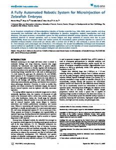
Atmospheric refraction can change dramatically throughout the day, creating a bias in displacement results computed at different times of the day. This can be seen on the left side in Fig. 1, which illustrates the bias in the vertical displacement results for cycles that were observed in the afternoon and at night at the Diamond Valley Lake water reservoir in California. In this case, if only comparisons between single cycles were relied upon for alarms, many false alarms would be generated.
4 am
Weekly Averages
Fig. 1. Comparison of time-of-day refraction effects and weekly averages. Cycle averaging is used to randomize the systematic effects of atmospheric refraction. The averaging of cycles that have been observed in varying conditions throughout the day improves the accuracy and reliability of the displacement determinations. The plot on the right in Fig. 1 illustrates the more reliable results obtained from the weekly averages. In slope stability monitoring, it is common to encounter lines of sight that graze the side of an embankment, where the temperature gradient increases near the surface. The temperature gradient can change very rapidly with sun exposure, particularly between day and night. Areas that receive direct sunlight can produce temperature gradients of several degrees per metre that may fluctuate rapidly (i.e., scintillation). In contrast, the same area at night may have a very stable, slowly decreasing temperature gradient as it releases heat.
2.2 Unstable Reference Points In deformation surveys, the definition of the datum is adversely affected by the use of reference points that are erroneously assumed stable. This in turn gives a biased displacement pattern that can easily lead to a misinterpretation of what is really happening to the deformable object. The identification and removal of the effects of unstable reference points has been the focus of research at the University of New Brunswick (UNB).
A methodology utilizing an iterative weighted similarity transformation (IWST) was developed at UNB by Chen and Chrzanowski [Chen, 1983; Chen et al., 1990]. The techniques have been successfully applied in all types of engineering projects where reference point stability has been a concern (see Chrzanowski et al. [1991]). An example of the IWST used to determine the true displacement field of a concrete dam is illustrated in Fig. 2: on the left is the displacement field obtained when creating the datum using what were thought to be stable reference stations, while on the right the IWST was utilized to obtain the datum independent displacements. The IWSTderived displacement trend, with the datum biases removed, gives the expected result of systematic concrete expansion between the two measurement cycles. This interpretation would be very difficult, if not impossible, to obtain from the figure on the left.
Fig. 2. Use of IWST to remove effect of unstable reference points. The methodology is based on using the stability of each of the reference points to determine its contribution to the datum. It is an iterative process that weights reference point contributions based on their displacement from the previous iteration. This computational approach is utilized in the ALERT software to eliminate unstable reference points and RTSs.
2.3 Tropospheric Zenith Delay and Multipath With the implementation of GPS sensors, the systematic effects of residual tropospheric zenith delay and multipath of phase signals become the primary limiting factors in achieving accuracies of a few millimetres in short baselines [Bond et al., 2003]. In tropospheric zenith delay, the elevation component is very difficult to differentiate from the zenith delay, therefore, any residual bias is mapped directly into the baseline height component. To differentiate between the two requires the observation of low elevation satellites, which due to the sky blockage typically created by pit walls, are rare. In addition, in slope stability applications it is very common to have large height variations between stations, which may magnify this effect. Multipath is created, in simple terms, by receiving both the primary and reflected waves at the antenna. The reflected waves have the effect of biasing the range measurements by some amount that depends on the satellite position, trajectory, and location of the reflecting surfaces. The bulk of the multipath is predominantly of short wavelength lasting a few minutes [Bond et al., 2003]. In open pit mine applications there are many surfaces that signals can reflect from to create multipath, creating a very harsh GPS environments.
3. Multisensor capability Multiple sensors improve the accuracy, and particularly the reliability, of the displacement results. Each RTS observes a distance, horizontal direction, and zenith angle and therefore is only able to uniquely determine the three-dimensional position of each target point that is
observed. This does not allow for any statistical analysis or verification of the results for each cycle. In these cases, it is not possible to pointing or refraction errors from true movement. When simply treating the observations from multiple RTSs independently the situation improves dramatically. For every object point that has multiple observations, it can be verified whether any computed displacement is similar for both sets of observations and whether they agree with the previous cycle results. Therefore, it creates a mechanism for identifying possible mispointings or refraction effects before a false alarm is activated. However, the best situation occurs when observations from multiple RTSs are combined. This allows for a complete statistical analysis for the measurements from each cycle. Any blunders in the pointings, as well as an estimate for whether the precision of the observation set was as expected, will be identified. Small mispointing or refraction errors are reduced, as they are smoothed by the least squares process. The largest improvement is in the determination of the horizontal displacements. When multiple RTSs are combined the horizontal coordinates become a function of the observed distances (which are less affected by temperature gradients), while the horizontal directions serve simply as a blunder detection tool. The result is horizontal coordinates that remain consistent to a few millimetres, cycle-to-cycle, and only change if the point actually moves beyond these amounts. Of course, this is based on the assumption that meteorological sensors are being used, allowing the distances to be corrected for atmospheric variations. Unfortunately, unless the lines of sight are very steep, the distances contribute very little to the elevation determination. The elevations are therefore still primarily determined by the zenith angle measurement, which can be adversely influenced by refraction. The refraction effects on the zenith angles cannot be eliminated, but can be reduced by using multiple RTSs and reducing the sight lengths. However, the closer the RTSs are to the monitoring area, the greater the chance of having an unstable instrument location. In addition, the distances to most reference targets would increase. This in turn would force the bulk of the inaccuracies to the reference target observations, which would reduce the confidence in being able to detect an unstable instrument, particularly in height. A solution to this problem is to add additional sensor types to the analysis that are less dependent on sight lengths and atmospheric conditions. A GPS antenna, mounted with each RTS, would allow the position of the observing station to be determined independently for each cycle. Each instrument position can be updated for each cycle, eliminating the need to observe multiple reference targets. The update would be with respect to a master station outside the zone of influence. For complete reliability, multiple master stations could be utilized. This would make it possible to verify the stability of the master stations by using the IWST methodology. Feasibility studies of GPS performance have been conducted at HVC (see section 5 below). Another feasible approach for verifying stability, that uses fewer GPS receivers, would be to install some geotechnical or rock mechanics instrumentation to monitor the change in antenna position. The additional instrumentation could be used anywhere within the area of concern to help improve the reliability of the monitoring system.
4. Software philosophy CCGE has developed a comprehensive automated monitoring system [Lutes et al., 2001]. The ALERT software implements the methodology for deformation monitoring and analysis that is described in this paper. The system has continued to evolve, with features being added to improve accuracy, increase reliability, and address user needs as they are identified. The software allows for a remote control and pre-programming of observations with RTSs and other sensors. It allows fully automatic reduction and processing of positioning surveys, automatic identification of unstable reference stations using the IWST, and automatic determination and graphical presentation of displacements of monitored points with their variance-covariance information.
The system takes advantage of the core functionality of the Microsoft Windows NT systems (e.g., NT 4.0, Windows 2000, and Windows XP). There is full support for remote operation via LAN and Internet connections and provider-independent database access (Fig. 3 illustrates a typical configuration). In addition, the software’s observation and processing tasks are automated according to any desired schedule and the system is able to recover from power outages with no user intervention.
Fig. 3. A typical computer network configuration for remote access. The result of data processing is a series of time-tagged coordinate values that are stored in the project database. Plotting utilities allow rapid visualization of displacement trends and advanced trend analysis, such as grouping observation cycles into mean values to smooth the effects of daily refraction. Because the database is in a readily accessible format, the end user can easily extract coordinate values using standard Structured Query Language (SQL) queries and build plotting and analysis tools to meet specialized needs.
5. Highland valley copper application The monitoring system application at the HVC mine is difficult due to long sight lengths, demanding accuracy requirements, and frequent reporting frequency. HVC uses more than 420 target prisms and the ALERT system to monitor pit walls in two large open pit mines, the Lornex and Valley pits, that have different accuracy requirements [Wilkins et al., 2003]. In total, four RTSs are used for monitoring with two located in each of the pits. The Valley pit, having the more stringent requirements due to its hard rock composition, has long lines of sight that exceed 1200 m and requires displacement detection accuracy to be better than 5 mm [Newcomen et al., 2003]. Fig. 4 (left-hand photograph) illustrates a typical RTS installation shelter for the Valley pit with a view of the extremely steep pit wall in the background.
Fig. 4. Instrumentation setups at Highland Valley Copper.
In this environment, the long sight lengths create a very hostile environment with large variations between cycles due to refraction. The long sight lengths, combined with the systematic effects of refraction, make it impossible to detect displacements at the 5 mm level with a single RTS. Therefore, the monitoring system makes use of sighting targets with multiple RTSs to increase the redundancy, hence, the accuracy of the displacement determinations (see section 3 above). The use of multiple RTSs has a further benefit in that the horizontal positions of the targeted points can now be uniquely determined by the intersection of the distances. Fig. 5 illustrates the cycle-to-cycle displacements and the half-day and full-day averages determined for an object point using dual instruments at an average sight length of 1100 m.
Fig. 5. Cycle-to-cycle, half-day, and full-day averages for a point observed by dual RTSs. Although results from dual instrument sightings meet the specifications it isn’t feasible to use this approach to monitor all areas requiring continuous monitoring. In addition, the long sight lengths at the Valley pit and the large displacements at the crest of the Lornex pit make it very difficult to find suitable locations for reference points. Therefore, a feasibility study has been undertaken to evaluate the possibility of using GPS to monitor and update the RTS locations between cycles. The primary goals of the study are to determine what accuracies are achievable, the best observing sessions, length of sessions, minimum required satellite geometry per session, and available report frequency. Fig. 4 (right-hand photograph) depicts a stand alone RTS/GPS hybrid test unit that was installed on the pit floor for an initial three day test period. An open pit mine is a very hostile environment to try to achieve a few millimeters accuracy in baseline components (particularly elevation). Due to the high pit walls, satellite outages occurred twice a day for approximately half-hour durations. In addition, there were long periods (up to 1.5 hours) where only 4 satellites were available. Nonetheless, the preliminary results of the three day test data obtained on the floor of the pit are encouraging. Fig. 6 shows the baseline component results when arbitrarily cutting the data into twenty four consecutive three-hour sessions. The height component clearly shows a downward trend with spikes occurring at the sessions where satellite coverage is the weakest. With session optimization and planning it is expected that the tolerances of less than 5 mm can be achieved.
Fig. 6. Baseline components for 3 days of 3-hour sessions for a station on the Valley Pit floor.
6. Conclusion The real time monitoring system developed by CCGE offers the possibility of fully automated reliable monitoring in remote areas. Once the system has been implemented, no human intervention is required to obtain displacement results. The observation gathering and processing can be scheduled to take place at preset intervals. Even if power failures occur, the system will automatically resume exactly where it left off without the loss of any data cycles. The use of multiple sensors increases the accuracy, and more importantly the reliability of the system. Horizontal displacements are better determined, and redundant vertical observations, although not fool proof, increase the reliability of height determinations. The inclusion of GPS sensors allows the instruments to be located closer to the monitored area (shorter lines of sight), which creates a significant increase in the system’s vertical reliability. The preliminary GPS baseline component results indicate that better than a 5 mm accuracy will be possible for at least some periods of the day. The inclusion of a variety of sensor types creates an extremely flexible monitoring system. GPS augmented with geotechnical sensors could create a very reliable method of maintaining instrument stabilities. If deemed beneficial, the geotechnical sensors could also be implemented as stand alone instruments. This would provide another means of increasing the monitoring scheme’s reliability. Research and development activities are continuing in this area. With these increases in reliability the number of false alarms will be dramatically reduced. Of course, one needs to err on the side of caution, but many unwarranted alarms can be eliminated.
Acknowledgements The authors acknowledge financial assistance for this research from the Atlantic Canada Opportunities Agency’s (ACOA) Atlantic Innovation Fund (AIF) and from the Natural Sciences and Engineering Research Council of Canada (NSERC). The support from Ralf Kintzi, Warren Newcomen, and Loyed Shwydiuk of Highland Valley Copper is gratefully acknowledged.
References Bond, Jason, Donghyun (Don) Kim, Richard B. Langley, and A. Chrzanowski (2003). “An investigation on the use of GPS for deformation monitoring in open pit mines.” Proceedings of the Fourth International Conference on Computer Applications in the Minerals Industry, Calgary, Alberta, Canada, September 8-10. Chen, Y.Q. (1983). “Analysis of deformation surveys – a generalized method.” Department of Geodesy and Geomatics Engineering Technical Report No. 94, University of New Brunswick, Fredericton, New Brunswick, Canada.
Chen, Y.Q., A. Chrzanowski, and J.M. Secord (1990). “A strategy for the analysis of the stability of reference points in deformation surveys.” CISM Journal, Vol. 44, No. 2, pp. 141-149. Chrzanowski, A., Y.Q. Chen, J.M. Secord, and A. Szostak-Chrzanowski (1991). “Problems and solutions in the integrated monitoring and analysis of dam deformations.” CISM Journal, Vol. 45, No. 4, pp. 547-560. Duffy, M., C. Hill, C. Whitaker, A. Chrzanowski, J. Lutes, and G. Bastin (2001). “An automated and integrated monitoring scheme for Diamond Valley Lake in California.” Proceedings of the 10th FIG International Symposium on Deformation Measurements, Orange, California, March 19-22, pp. K1-K23. Lutes, J., A. Chrzanowski, G. Bastin, C. Whitaker (2001). “DIMONS Software for automatic data collection and automatic deformation analysis.” Proceedings of the 10th FIG International Symposium on Deformation Measurements, Orange, California, March 1922, pp.101-109. Newcomen, Warren H., C. Murray and L. Shwydiuk (2003). “Monitoring pit wall deformations in real time at Highland Valley Copper.” Proceedings of the Fourth International Conference on Computer Applications in the Minerals Industry, Calgary, Alberta, Canada, September 8-10. Wilkins, R., A. Chrzanowski, G. Bastin, W. Newcomen, L. Shwydiuk (2003). “A Fully automated system for monitoring pit wall displacements.” A paper presented at the 2003 SME annual meeting, Cincinnati, Ohio, Feb 24-26.