Jun 27, 2016 - uma implementação viável em tempo real. O método algébrico permite estimar os estados do sistema de maneira rápida e não-assintótica.
Matheus Schwalb Moraes
Algebraic Derivative Estimation Applied to Nonlinear Control of Magnetic Levitation
São Paulo 2016
Matheus Schwalb Moraes
Algebraic Derivative Estimation Applied to Nonlinear Control of Magnetic Levitation
Dissertation submitted to the Polytechnic School of University of São Paulo in partial fulfillment of the requirements for the degree of Master of Science in Electrical Engineering. Concentration: Control Systems Engineering
Universidade de São Paulo Escola Politécnica Programa de Pós-Graduação em Engenharia Elétrica
Supervisor: Prof. Dr. Paulo Sergio Pereira da Silva
São Paulo 2016
Este exemplar foi revisado e corrigido em relação à versão original, sob responsabilidade única do autor e com a anuência de seu orientador. São Paulo, 1 de Maio de 2016 Assinatura do autor:
______________________
Assinatura do orientador: ______________________
Moraes, Matheus Schwalb Algebraic Derivative Estimation Applied to Nonlinear Control of Magnetic Levitation/ M. S. Moraes – versão corr. – São Paulo, 2016. 54 p. Dissertação (Mestrado) - Escola Politécnica da Universidade de São Paulo. Departamento de Engenharia de Telecomunicações e Controle. 1.Levitação Magnética 2.Estimação de Derivadas 3.Controle Adaptativo 4.Controle Não Linear I.Universidade de São Paulo. Escola Politécnica. Departamento de Engenharia de Telecomunicações e Controle II.t.
Matheus Schwalb Moraes
Algebraic Derivative Estimation Applied to Nonlinear Control of Magnetic Levitation
Dissertation submitted to the Polytechnic School of University of São Paulo in partial fulfillment of the requirements for the degree of Master of Science in Electrical Engineering. Concentration: Control Systems Engineering
Prof. Dr. Paulo Sergio Pereira da Silva Orientador
Prof. Dr. Roberto Moura Sales Convidado
Dr. Paulo Sérgio Pierri Convidado
São Paulo 2016
Acknowledgements To my parents, Marister and Sergio, who always gave me the wholehearted support to overcome difficult times. To my advisor, Dr. Paulo Sergio, for his attention and elegant ideas to treat math problems. To the Brazilian Navy Technological Center, for the technical and financial support.
Abstract The subject of this thesis is the real-time implementation of algebraic derivative estimators as observers in nonlinear control of magnetic levitation systems. These estimators are based on operational calculus and implemented as FIR filters, resulting on a feasible real-time implementation. The algebraic method provide a fast, non-asymptotic state estimation. For the magnetic levitation systems, the algebraic estimators may replace the standard asymptotic observers assuring very good performance and robustness. To validate the estimators as observers in closed-loop control, several nonlinear controllers are proposed and implemented in a experimental magnetic levitation prototype. The results show an excellent performance of the proposed control laws together with the algebraic estimators. Keywords: derivative estimation, adaptive control, nonlinear control, magnetic levitation
Resumo O tema dessa dissertação é a implementação em tempo real dos estimadores algébricos de derivadas como observadores no controle não-linear de levitação magnética. Esses estimadores são baseados no cálculo operacional e implementados como filtros FIR, resultando em uma implementação viável em tempo real. O método algébrico permite estimar os estados do sistema de maneira rápida e não-assintótica. Para os sistemas de levitação magnética, os estimadores algébricos podem substituir os observadores assintóticos assegurando boas propriedades de robustez e performance. A fim de validar os estimadores como observadores no controle em malha fechada, vários controladores não-lineares são propostos e implementados em um protótipo experimental. Os resultados mostram uma excelente performance dos controladores propostos juntamente com os estimadores algébricos.
Palavras-chave: estimação de derivadas, controle adaptativo, controle não-linear, levitação magnética
Contents 1
INTRODUCTION . . . . . . . . . . . . . . . . . . . . . . . . . . . . 13
1.1
Objectives . . . . . . . . . . . . . . . . . . . . . . . . . . . . . . . . . . 13
1.2
Motivation and Justification . . . . . . . . . . . . . . . . . . . . . . . 13
1.3
Literature Review . . . . . . . . . . . . . . . . . . . . . . . . . . . . . . 14
1.4
Observers in Control Systems . . . . . . . . . . . . . . . . . . . . . . . 14
2
ALGEBRAIC DERIVATIVE ESTIMATION . . . . . . . . . . . . . . 21
2.1
First Order Estimators . . . . . . . . . . . . . . . . . . . . . . . . . . . 21
2.1.1
Introductory Example: First Order Filtering . . . . . . . . . . . . . . . . . 21
2.1.2
First Order Derivative Estimation . . . . . . . . . . . . . . . . . . . . . . 22
2.2
Second Order Estimators . . . . . . . . . . . . . . . . . . . . . . . . . 23
2.2.1
Second Order Filtering . . . . . . . . . . . . . . . . . . . . . . . . . . . . 23
2.2.2
First Order Derivative Estimation . . . . . . . . . . . . . . . . . . . . . . 24
2.2.3
Second Order Derivative Estimation . . . . . . . . . . . . . . . . . . . . . 24
2.3
Third Order Estimators . . . . . . . . . . . . . . . . . . . . . . . . . . 25
2.3.1
Second Order Derivative Estimation . . . . . . . . . . . . . . . . . . . . . 25
2.4
Discrete Implementation of the Algebraic Derivative Estimators . . 26
3
NONLINEAR CONTROL OF THE MAGNETIC LEVITATION SYSTEM . . . . . . . . . . . . . . . . . . . . . . . . . . . . . . . . . . . 31
3.1
System Dynamics . . . . . . . . . . . . . . . . . . . . . . . . . . . . . . 31
3.2
Tracking Control Law for the Nominal System . . . . . . . . . . . . . 32
3.3
Feedback Linearization with Integrator . . . . . . . . . . . . . . . . . 33
3.4
Lyapunov-Based Adaptive Control . . . . . . . . . . . . . . . . . . . . 36
3.5
Least Squares Adaptive Control . . . . . . . . . . . . . . . . . . . . . 38
4
MODEL-FREE CONTROL . . . . . . . . . . . . . . . . . . . . . . . 41
4.1
Ultra-local Model . . . . . . . . . . . . . . . . . . . . . . . . . . . . . . 41
4.2
Control Law . . . . . . . . . . . . . . . . . . . . . . . . . . . . . . . . . 41
4.2.1
PD Tuning . . . . . . . . . . . . . . . . . . . . . . . . . . . . . . . . . . 42
4.2.2
PID Tuning . . . . . . . . . . . . . . . . . . . . . . . . . . . . . . . . . . 42
4.3
Online Identification of the Ultra-local Model Parameter
4.3.1
Identification through Algebraic Estimation (ALG) . . . . . . . . . . . . . . 42
4.3.2
Identification through Derivative Estimation (ACC) . . . . . . . . . . . . . 44
5
CONCLUSIONS AND REMARKS . . . . . . . . . . . . . . . . . . . 47
. . . . . . 42
BIBLIOGRAPHY
APPENDIX
. . . . . . . . . . . . . . . . . . . . . . . . . . . . 49
51
APPENDIX A – EXPERIMENTAL SETUP . . . . . . . . . . . . . 53
13
1 Introduction 1.1 Objectives The objective of this dissertation is the study of the algebraic derivative estimation techniques as non-asymptotic observers in nonlinear control of a magnetic levitation system. This study involves the implementation of several nonlinear control laws, e.g, feedback linearization, nonlinear adaptive, model free, together with the algebraic estimators in a laboratory prototype.
1.2 Motivation and Justification The present work is justified by the study and implementation of modern state observation techniques together with several nonlinear control laws. The magnetic levitation control is usually designed using linear control theory after linearizing the system model around a nominal gap. Although this method is efficient when the control operates near the nominal gap, it tends to have a poor performance when the desired trajectory starts far from the operating point, since the linear approximation is no longer valid. In this way, the system could present large overshoots for levitations starting with large gaps, or even instability. Recalling that magnetic levitation systems are nonlinear and unstable in open loop, nonlinear controllers have more interesting properties when compared to linear control, considering the need to minimize the tracking error through the entire levitation path. At the same time, the algebraic method can provide a fast, non-asymptotic and precise state estimation to the control law. Besides showing the efficiency of the algebraic estimators in closed loop nonlinear control, this work also aims the study and implementation of modern controllers, e.g., nonlinear adaptive and model-free control. Despite the fact that the control and estimation theory presented in this work is implemented in the magnetic levitation system, it is also useful for a large range of dynamical systems. This dissertation is written in a way that the control law designs are developed independently of the algebraic estimation techniques. Even though this work focuses on algebraic estimation, nothing prevents one from using other estimation approaches together with the proposed feedback control laws.
14
Chapter 1. Introduction
1.3 Literature Review The algebraic estimation techniques first presented in (FLIESS; SIRA-RAMIREZ, 2004) provide a fast and precise parameter identification of linear systems. By identifying the coefficients of an arbitrary order polynomial model of the signal, the algebraic techniques can be used for derivative estimation as in (MBOUP; JOIN; FLIESS, 2007), where individual estimators are used for each coefficient instead of simultaneous estimation, avoiding a possible ill-conditioned matrix inversion which leads to poor estimations specially in a noisy setting. A more complete reference for derivative estimation can be found in (MBOUP; JOIN; FLIESS, 2009), including details of the sliding-window estimation. These are the main references concerning state estimation through algebraic derivative techniques. In nonlinear control, the Lyapunov-based adaptive control and the Least-squares estimation presented in this dissertation are modified versions inspired on (SLOTINE; LI et al., 1991). Both approaches relies on the feedback linearization control, also presented in this reference. The Lyapunov-based approach has an error based update law for the uncertain parameter, while the Least-squares identify the parameter through input-output measures of the system. In this dissertation, a special attention will be given for Model-free control, which is a novel approach presented in (FLIESS; JOIN, 2008) and (FLIESS; JOIN, 2009). This technique aims the simplification of nonlinear control by using a generic model which is identified on real time through algebraic estimation. Several practical examples can be found in (FLIESS; JOIN, 2013).
1.4 Observers in Control Systems State observers plays an important role in control systems, considering that the estimation of states that are not directly measured is needed for stabilization and tracking control. A simple example is the following second order linear system which represents a free unit mass on space, where x is the output (position) and u is the control input (force): x¨ = u
(1.1)
y=x It’s impossible to stabilize this system without using an estimation of x˙ (velocity), since there is no control input of the form: u = −kx , k ∈ R
(1.2)
that can drive x in Eq.(1.1) to zero, considering the presence of an initial condition x0 = a. This fact is easily obtained through the analysis of the system in the Laplace domain, since
1.4. Observers in Control Systems
15
√ the poles will be s = ± −k, leading to instability if k < 0 or an undamped oscillation if k > 0. On the other hand, the state feedback law: u = −λ2 x − 2λx˙ , λ ∈ R+
(1.3)
stabilizes the system, resulting in two stable poles equal to −λ in the closed loop system x¨ + λ2 x + 2λx˙ = 0. For tracking control, one can simply stabilize the error between the position and the desired trajectory xd . For this purpose, the control law would be: u = x¨d − λ2 x˜ − 2λx˜˙ , λ ∈ R+
(1.4)
where x˜ = x−xd is the tracking error. The resulting closed loop dynamics x¨˜ +λ2 x˜ +2λx˜˙ = 0 is stable and the tracking error converges to zero. In real applications the value of x is measured in a noisy environment causing the well known noise amplification in the calculation of x, ˙ since the pure differentiator has an unlimited gain that grows with higher frequencies. This issue motivated the use of filtering techniques, which attenuate high frequency noises but induce an estimation delay in the closed loop control system. This delay may cause undesired effects such as oscillations or even instability. Generally, faster system dynamics need smaller delays in state estimation to avoid instability. When the signal measured is the output of a well modeled dynamic system, the model-based observer approach is a good way to estimate the system states. State observer is a nomenclature used to describe an auxiliary dynamic system whose states converge to the real states of the system. For our free mass system control, an observer allows the estimation of the mass velocity x2 , which is needed for stabilization and tracking control. A possible observer based control would be:
x˙ 1 = x2 x˙ 2 = u
(1.5)
y 1 = x1 xˆ˙ 1 = xˆ2 − 2Kobs (ˆ x1 − x1 ) xˆ˙ 2 = u − K 2 (ˆ x1 − x1 ) obs
yˆ1 = xˆ1
(1.6)
yˆ2 = xˆ2 Kobs ∈ R+ u = x˙ 2d − λ2 (x1 − x1d ) − 2λ(ˆ x2 − x2d ) λ ∈ R+
(1.7)
16
Chapter 1. Introduction
Eqs.(1.5) are the state space representation of the free mass system dynamics, Eqs.(1.6) are the observer and Eq.(1.7) is the control law, which stabilizes the trajectory error. x1d is the desired trajectory imposed to the system, where x˙ 1d = x2d . Considering the observation errors e1 = xˆ1 − x1 and e2 = xˆ2 − x2 , the observer error dynamics can be derived subtracting Eqs.(1.5) from Eqs.(1.6) : e˙ 1 = e2 − 2Kobs e1
(1.8)
2 e˙ 2 = −Kobs e1
The above formulation results in the following matrix representation:
=
e˙ 1 e˙ 2
−2Kobs 1 2 −Kobs
0
e1 e2
(1.9)
The eigenvalues of the matrix are both stable and equal to −Kobs , driving the observation error to zero asymptotically. In real applications, the observer eigenvalues are chosen to provide an estimation much faster than the controlled system poles. This choice provides a fast state estimation, avoiding transients of long duration. On the other hand, high gains could cause a large transitory overshoot (peaking) when the observer initial states are distant from the system states. It is important to notice that closing the feedback loop with an observer generates a new dynamic system, where the observer dynamics interacts with the controlled system. For linear systems, the separation principle allows the independent design of the controller and the observer. The most important result is that the combination of a stable observer with a stable state feedback is also stable. Although some advances were made towards a nonlinear version of the separation principle, the general problem remains open and each case has to be analyzed independently. To overcome this issue, several techniques involving observer robustness were proposed, such as high gain observers (KHALIL, 2008) and sliding mode observers (DRAKUNOV; UTKIN, 1995), which are variations of the linear observer proposed in (LUENBERGER, 1964). These techniques have the advantage of robustness in the presence of model uncertainties, and can be modified to be used as numerical differentiation schemes (LEVANT, 1998). In this dissertation, the algebraic identification techniques proposed in (FLIESS; SIRA-RAMIREZ, 2004) and specifically used in derivative estimation in (MBOUP; JOIN; FLIESS, 2007) will be investigated and used as observers in magnetic levitation control, providing state estimation in a fast, non-asymptotic and model independent way. To exemplify some advantages of using the algebraic approach for the state estimation task, a comparison between the algebraic derivative estimation and the model-based observer is shown below. The free-mass system of Eq.(1.5) is controlled by the state feedback law of Eq.(1.7) using these different observation approaches to estimate the
1.4. Observers in Control Systems
17
state x2 (mass velocity). The control using the velocity estimation of a simple first order derivative linear filter : s H(s) = (1.10) 0.08s + 1 is also included. All simulations were performed with initial conditions x1 (0) = 1, x2 (0) = 0 and λ = 5 defining the control gains in Eq.1.7. The observer gains are defined by Kobs = 12 and xˆ1 (0) = xˆ2 (0) = 0. Notice that the observer poles are faster than the control poles. A zero-mean Gaussian noise with a variance equal to 10−4 is added to the position measure to represent the sensor noise. Figure 2 – Classic Observer, m = 1kg
Figure 1 – Classic Observer, m = 1kg 1.5
4
Position [m]
0.5
Velocity [m/s]
x1 x1d
1
0 -0.5
x ˆ2 x2
2 0 -2
-1 -1.5
-4 0
1.5
3 Time [s]
4.5
6
Figure 3 – Algebraic Method, m = 1kg
0
1.5 Time [s]
2.25
3
Figure 4 – Algebraic Method, m = 1kg
1.5
4
0.5
Velocity [m/s]
x1 x1d
1 Position [m]
0.75
0 -0.5
x ˆ2 x2
2 0 -2
-1 -1.5
-4 0
1.5
3 Time [s]
4.5
6
0
0.75
1.5 Time [s]
2.25
3
The simulation shows the good tracking performance of all cases. The classic observer exhibits the "peaking" phenomena (Fig.2), since the observer initial states were different from the system initial states. This fact degrades the beginning of the tracking, without affecting the overall performance (Fig.1). The approaches using the algebraic and linear filter derivatives performed well, while the algebraic method provided much less noisy and delayed estimations compared to the linear filter (zoomed comparison Fig.7-8).
18
Chapter 1. Introduction
Figure 5 – Linear Filter, m = 1kg
Figure 6 – Linear Filter, m = 1kg
1.5
4
Position [m]
0.5
Velocity [m/s]
x1 x1d
1
0 -0.5
x ˆ2 x2
2 0 -2
-1 -1.5
-4 0
1.5
3 Time [s]
4.5
6
0
Figure 7 – Algebraic, m = 1kg
1.5 Time [s]
2.25
3
Figure 8 – Linear Filter, m = 1kg 1 Velocity [m/s]
1 Velocity [m/s]
0.75
0
-1
x ˆ2 x2
-2
0
-1
x ˆ2 x2
-2 0
0.25
0.5 Time [s]
0.75
1
0
0.25
0.5 Time [s]
0.75
1
It’s important to notice that a noisier estimation implies that the control signal is noisier, what is not interesting in practical applications. The interesting results are obtained when the control law projected for the unitary mass m1 = 1kg is used for the tracking task of a mass m2 = 0.14kg, considering the same free mass system m¨ x = u . The poor observer model (projected for m = 1kg) leads to a severe degradation of tracking performance in the classic observer approach (Fig.9-10). This faulty state estimation could even lead to instability. The algebraic and linear filter cases present good tracking performance, although the algebraic approach presents better accuracy and less noise in the estimation (zoomed comparison in Fig.15-16). As expected, the control effort is also noisier when the linear filter estimation is used (zoomed comparison Fig.17-18). The main objective of these simulations is showing that the proposed control law can lead to good tracking performance for a large range of mass values while the combination of the control law with the classic observer can’t, since the classic observer provides a poor velocity estimation when the observer mass value is far from the real mass. In these cases, the estimation based on derivatives, which is not model based, outperform
1.4. Observers in Control Systems
19
the classic observer approach. The algebraic estimation provides much faster and reliable estimations in comparison to the noisier and delayed linear filter. Figure 9 – Classic Observer, m = 0.14kg
Figure 10 – Classic Observ., m = 0.14kg
1.5
15
x1 x1d
0.5 0 -0.5 -1
5 0 -5 -10
-1.5
-15 0
1.5
3 Time [s]
4.5
6
0
Figure 11 – Algebraic, m = 0.14kg
0.75
1.5 Time [s]
2.25
3
Figure 12 – Algebraic, m = 0.14kg
1.5
2
0.5
Velocity [m/s]
x1 x1d
1 Position [m]
x ˆ2 x2
10 Velocity [m/s]
Position [m]
1
0 -0.5
x ˆ2 x2
0
-2
-1 -1.5
-4 0
1.5
3 Time [s]
4.5
6
Figure 13 – Linear Filter, m = 0.14kg
0
1.5 Time [s]
2.25
3
Figure 14 – Linear Filter, m = 0.14kg
1.5
2
0.5
Velocity [m/s]
x1 x1d
1 Position [m]
0.75
0 -0.5
x ˆ2 x2
0
-2
-1 -1.5
-4 0
1.5
3 Time [s]
4.5
6
0
0.75
1.5 Time [s]
2.25
3
20
Chapter 1. Introduction
Figure 15 – Algebraic, m = 0.14kg
Figure 16 – Linear Filter, m = 0.14kg 2 Velocity [m/s]
Velocity [m/s]
2
0
-2
x ˆ2 x2
-4
0
-2
x ˆ2 x2
-4 0
0.25
0.5 Time [s]
0.75
1
Figure 17 – Algebraic, m = 0.14kg
0
0.25
0.5 Time [s]
0.75
Figure 18 – Linear Filter, m = 0.14kg
20
20
u
u 10 Force [N]
10 Force [N]
1
0 -10
0 -10
-20
-20 0
0.25
0.5 Time [s]
0.75
1
0
0.25
0.5 Time [s]
0.75
1
21
2 Algebraic Derivative Estimation The algebraic derivative estimation method is based on the identification of the coefficients of an arbitrary order truncated Taylor expansion. For this purpose, we assume that the signal y˜(t) is an analytic function, and can be approximated by a truncated Taylor expansion calculated on t = 0: y˜(t) ' y(t) =
n X y (j) (0) j=0
j!
tj
(2.1)
This identification procedure consists in several algebraic manipulations on the operational domain, which has the same properties of the Laplace transform. Finally, the resulting expression is transformed back to time domain, and the resulting estimation filters are discretized as sliding-window FIR filters, which can be simply implemented on real-time applications. A general formulation for arbitrary order estimators can be found in (MBOUP; JOIN; FLIESS, 2007) and (ZEHETNER; REGER; HORN, 2007). In this dissertation, the estimators will be constructed step by step to illustrate the main ideas of the algebraic method.
2.1 First Order Estimators 2.1.1 Introductory Example: First Order Filtering Consider the first order approximation of the noisy signal y˜(t) arround t = 0: y(t) = a0 + a1 t
(2.2)
After applying the Laplace Transform, Eq.(2.2) leads to the following expression in the operational domain: a0 a1 Y (s) = + 2 (2.3) s s Multiplying both sides by s2 : s2 Y (s) = sa0 + a1
(2.4)
In this way, a1 is isolated and can be eliminated multiplying both sides of the d equality by the differential operator ds : 2sY (s) + s2
d Y (s) = a0 ds
(2.5)
22
Chapter 2. Algebraic Derivative Estimation
Multiplying both sides by s13 for the elimination of time derivatives and filtering, letting every factor involving Y (s) be integrated at least one time1 : 2
a0 1 1 d Y (s) = Y (s) + s2 s ds s3
(2.6)
The right part of the above equation is transformed to time domain using the relation: c tα−1 (2.7) , α ≥ 1 , c ∈ C ←→ c sα (α − 1)! Remembering that the differentiation of Y (s) with respect to s is related to a multiplication by −t in time domain and left multiplying Y (s) by s1α , α ≥ 1 corresponds to iterated integrals, the Cauchy formula for repeated integration may be used to provide dn a closed-form expression for the operator s1α ds n in a single integral: 1 dn (−1)n Z t Y (s) ←→ (t − τ )α−1 τ n y(τ ) dτ sα dsn (α − 1)! 0
(2.8)
Transforming Eq.(2.6) back to time domain using Eq.(4.11) and Eq.(4.12), one gets: 2
Z t
Z t
0
0
(t − τ )y(τ ) dτ −
τ y(τ ) dτ = a0
t2 2!
(2.9)
Rearranging the expression, an identifier for the parameter a0 is obtained: 2Zt a0 = 2 (2t − 3τ )y(τ ) dτ t 0
(2.10)
Substituting y(t) by y˜(t), Eq.(2.10) can be seen as a first order filtered approximation of the signal, valid in a short time estimation window for t > 0. Details of the sliding-window digital implementation of the estimators will be given in the next chapter.
2.1.2 First Order Derivative Estimation Consider the first order approximation of the noisy signal y˜(t) arround t = 0, already written in the operational domain: Y (s) =
a0 a1 + 2 s s
(2.11)
a1 s
(2.12)
Multiplying both sides by s: sY (s) = a0 +
In this way, a0 is isolated and can be eliminated multiplying both sides of the d equality by the differential operator ds : Y (s) + s 1
d a1 Y (s) = − 2 ds s
In this context, the iterated integrals are low-pass filters which attenuate noises.
(2.13)
2.2. Second Order Estimators
23
Multiplying both sides by s12 for the elimination of time derivatives and filtering, letting every factor involving Y (s) be integrated at least one time: Y (s) 1 d a1 Y (s) = − 4 + 2 s s ds s
(2.14)
Using the well known rules of Laplace Transform and the Cauchy formula for repeated integration gives: Z t
Z t
0
0
(t − τ )y(τ ) dτ −
τ y(τ ) dτ = −a1
t3 3!
(2.15)
Rearranging the expression, the first order derivative estimation is obtained: 6Zt a1 = − 3 (t − 2τ )y(τ ) dτ (2.16) t 0
2.2 Second Order Estimators 2.2.1 Second Order Filtering Consider the second order approximation of the noisy signal y˜(t) arround t = 0: t2 2
(2.17)
a0 a1 a2 + 2+ 3 s s s
(2.18)
y(t) = a0 + a1 t + a2 Applying the Laplace Transform: Y (s) =
Multiplying by s3 , in order to isolate a2 : s3 Y (s) = s2 a0 + sa1 + a2 Multiplying by
d ds
to eliminate a2 : 3s2 Y (s) + s3
Multiplying by
d ds
1 , s4
6
d Y (s) = 2sa0 + a1 ds
(2.20)
to eliminate a1 :
6sY (s) + 6s2 Multiplying by
(2.19)
d d2 Y (s) + s3 2 Y (s) = 2a0 ds ds
(2.21)
for the elimination of time derivatives and filtering:
1 1 d 1 1 d2 Y (s) + 6 Y (s) = 2a0 4 Y (s) + 3 2 2 s s ds s ds s
(2.22)
Transforming back to time domain: 3
Z t
2
(t − τ ) y(τ ) dτ − 6
0
Z t
Z t
0
0
(t − τ )y(τ ) dτ +
τ 2 y(τ ) dτ = 2a0
Rearranging terms, the second order filter is obtained: 3Zt 2 a0 = 3 (3t − 12tτ + 10τ 2 )y(τ ) dτ t 0
t3 3!
(2.23)
(2.24)
24
Chapter 2. Algebraic Derivative Estimation
2.2.2 First Order Derivative Estimation Consider the second order approximation of the noisy signal y˜(t), already written in the operational domain: a0 a1 a2 + 2+ 3 Y (s) = (2.25) s s s Multiplying by s3 to isolate a2 : s3 Y (s) = s2 a0 + sa1 + a2
(2.26)
Differentiating with respect to s, in order to eliminate a2 : 3s2 Y (s) + s3
d Y (s) = 2sa0 + a1 ds
(2.27)
d a1 Y (s) = 2a0 + ds s
(2.28)
Multiplying by 1s , isolating a0 : 3sY (s) + s2
Differentiating with respect to s, in order to eliminate a0 : 3Y (s) + 5s Multiplying by
1 d d2 Y (s) + s2 2 Y (s) = −a1 2 ds ds s
(2.29)
1 : s3
3
1 1 d 1 d2 1 Y (s) + 5 Y (s) + Y (s) = −a1 5 3 2 2 s s ds s ds s
(2.30)
Transforming back to time domain: Z t Z t t4 3Z t 2 (t − τ ) y(τ ) dτ − 5 (t − τ )τ y(τ ) dτ + τ 2 y(τ ) dτ = −a1 2 0 4! 0 0
(2.31)
Rearranging the expression, the estimation of a1 is obtained: 12 Z t 2 a1 = − 4 (3t − 16tτ + 15τ 2 )y(τ ) dτ t 0
(2.32)
2.2.3 Second Order Derivative Estimation Consider the second order approximation of the noisy signal y˜(t), already written in the operational domain: a0 a1 a2 Y (s) = + 2+ 3 (2.33) s s s Multiplying by s2 to isolate a1 : s2 Y (s) = sa0 + a1 +
a2 s
(2.34)
2.3. Third Order Estimators d ds
Multiplying by
25
to eliminate a1 : d a2 Y (s) = a0 − 2 ds s
(2.35)
d2 d 1 Y (s) + s2 2 Y (s) = 2a2 3 ds ds s
(2.36)
2sY (s) + s2 d ds
Multiplying by
to eliminate a0 :
2Y (s) + 4s 1 : s3
Multiplying by
2
1 d2 1 1 d 1 Y (s) + Y (s) + 4 Y (s) = 2a 2 s3 s2 ds s ds2 s6
(2.37)
Transforming back to time domain: Z t
2
(t − τ ) y(τ ) dτ − 4
Z t
Z t
0
0
0
(t − τ )τ y(τ ) dτ +
τ 2 y(τ ) dτ = 2a2
t5 5!
(2.38)
Rearranging the expression, the second order derivative estimation is obtained: 60 Z t 2 a2 = y¨(t) = 5 (t − 6tτ + 6τ 2 )y(τ ) dτ t 0
(2.39)
2.3 Third Order Estimators The formulation of the third order estimators follows the same principles of the estimators of lower orders. In this dissertation, the second order derivative estimation through a third order Taylor expansion will be used some for specific control approaches. For this reason, only this estimator will be presented.
2.3.1 Second Order Derivative Estimation Consider the third order approximation of the noisy signal y˜(t) arround t = 0: y(t) = a0 + a1 t + a2
t2 t3 + a3 2! 3!
(2.40)
Applying the Laplace Transform: Y (s) =
a0 a1 a2 a3 + 2+ 3+ 4 s s s s
(2.41)
The identification of a2 follows the same method of the previous subsection, applying d2 1 d 4 the differential operator s14 ds 2 s ds s and transforming back to time domain. Multiplying Eq.(2.41) by s4 : s4 Y (s) = a0 s3 + a1 s2 + a2 s + a3
(2.42)
26
Chapter 2. Algebraic Derivative Estimation
Differentiating with respect to s, in order to eliminate a3 : 4s3 Y (s) + s4 Multiplying by
1 s
d Y (s) = 3s2 a0 + 2sa1 + a2 ds
(2.43)
to isolate a1 : 4s2 Y (s) + s3
d a2 Y (s) = 3sa0 + 2a1 + ds s
(2.44)
Differentiating with respect to s, in order to eliminate a1 : 8sY (s) + 7s2
d d2 a2 Y (s) + s3 2 Y (s) = 3a0 − 2 ds ds s
(2.45)
Differentiating with respect to s, in order to eliminate a0 : 8Y (s) + 8s
d d2 d2 d3 1 d Y (s) + 14s Y (s) + 7s2 2 Y (s) + 3s2 2 Y (s) + s3 3 Y (s) = 2a2 3 (2.46) ds ds ds ds ds s
Multiplying by
1 s4
for the elimination of time derivatives and filtering:
1 1 d 1 d2 1 d3 1 8 4 Y (s) + 22 3 Y (s) + 10 2 2 Y (s) + Y (s) = 2a2 7 3 s s ds s ds s ds s
(2.47)
Transforming back to time domain: Z t Z t t6 22 Z t 8 Zt 2 3 2 (t − τ ) y(τ ) dτ − (t − τ ) τ y(τ ) dτ + 10 (t − τ )τ y(τ ) dτ − τ 3 y(τ ) dτ = 2a2 3! 0 2 0 6! 0 0 (2.48)
Rearranging the expression, the second order derivative estimation is obtained: a2 = y¨(t) =
120 Z t 3 (4t − 45t2 τ + 108tτ 2 − 70τ 3 )y(τ ) dτ t6 0
(2.49)
The second order derivative estimation is obtained substituting y(τ ) by the noisy measure y˜(τ ) in the above expression.
2.4 Discrete Implementation of the Algebraic Derivative Estimators The estimators developed in the previous section aim the j-order derivative estimation of an arbitrary noisy signal y˜(t) that is modeled by a n-order truncated Taylor expansion calculated on t = 0: y˜(t) ' y(t) =
n X j=0
y (j) (0)
tj j!
(2.50)
2.4. Discrete Implementation of the Algebraic Derivative Estimators
27
The estimations are valid in a small time interval �. In the general case, the j-order derivative estimator when all factors involving y(t) are integrated at least one time can be summarized as: k Z t˜ y (t) ' y (0) = aj = P (t, τ )y(τ ) dτ , 0 < t < � p(t) 0 (j)
(j)
(2.51)
which may be implemented in a small time window with a fixed length T : Z T ˜ Z T k P (T, τ ) k ZT˜ aj = P (T, τ )y(τ ) dτ = y(τ ) dτ = P (T, τ )y(τ ) dτ p(T ) 0 p(T ) 0 0
(2.52)
The above expression provides an estimator for the parameter aj = y (j) (0) that holds only in the vicinity of t = 0, since the estimation is based on the Taylor series expansion around t = 0. In fact, the estimation is exact if the input signal is a noise-free polynomial. For an arbitrary signal, the estimation drifts as time passes. The reason why the estimation of aj = y (j) (0) is approximately equal to aj = y (j) (t) in a small interval 0 < t < � is the assumption that the input signal is well modeled by a polynomial in the vicinity of t. The estimator, however, is not causal: it requires the signal values y(t) for t > 0 to estimate the derivative on t = 0. This fact motivates an adaptation of the method to develop a causal estimator on an arbitrary time t. First, consider the Taylor expansion z(τ ) around τ = 0 of an arbitrary signal z˜(τ ), whose coefficients may be calculated using the estimators developed in this section: n X
Z T τj P (T, τ )z(τ ) dτ ⇒ aj = z˜(τ ) ' z(τ ) = aj j! 0 j=0
(2.53)
Considering the variable changes τ , t − θ and y(θ) , z(t − θ): n X
y(θ) , z(t − θ) =
j=0
aj
(t − θ)j j!
(2.54)
The above expression may be seen as a Taylor expansion of z˜(τ ) around θ = t, considering a signal inversion for the variable θ. Its easy to show that:
� dj � y (j) (t) = j z(t − θ) = (−1)j aj dθ θ=t
(2.55)
Introducing the variable changes in the expression for aj : aj =
Z T
P (T, τ )z(τ ) dτ =
Z T
0
P (T, τ )y(t − τ ) dτ
(2.56)
0
The final expression is a causal estimator calculated on a arbitrary time t, using a fixed estimation window of length T : aj = y (j) (t) = (−1)j
Z T 0
P (T, τ )y(t − τ ) dτ
(2.57)
28
Chapter 2. Algebraic Derivative Estimation
This estimator can be digitally implemented using the trapezoidal integration method, resulting in a digital FIR filter. For this purpose, we consider T = Ts N , where T is the estimation window, (N + 1) is the number of samples and Ts is a fixed sample time: aj = y (j) (t) ' (−1)j
N +1 X
αk P (T, τk )y(t − τk )
(2.58)
k=1
To reduce the computational effort, the discretization of P (T, τk ) is computed a priori. At the same time, we take into account the coefficients αk derived from the trapezoidal integration: h
Pˆαk (T, τk ) = α1 P (T, τ1 ) α2 P (T, τ2 ) ... αN +1 P (T, τN +1 )
i
τk = (k − 1)Ts Ts , k = 1 or k = N + 1 2 αk = Ts , k = 2, 3, ..., N
(2.59)
αk =
The buffer vector yˆ(t − τk ) containing the last N + 1 samples is vertically arranged. At each sample clock, the hole vector is shifted. The last value is discarded and the first position receives the newest value y(t):
yˆ(t − τk ) =
y(t) y(t − Ts ) .. .
(2.60)
y(t − Ts N )
Finally, Pˆαk (T, τk ) and yˆ(t − τk ) are multiplied at each sample time, providing a real time estimation of aj : aj (t) = y (j) (t) ' (−1)j
N +1 X
αk P (T, τk )y(t − τk ) = (−1)j Pˆαk (T, τk )ˆ y (t − τk )
(2.61)
k=1
It’s important to notice that the choice of the estimation window T establishes a trade off between noise immunity and precision. While smaller values of T account for a faster filter response and a better local modeling of the signal, bigger values improve noise immunity with better high-frequency filtering properties. Since the filter coefficients may have large magnitudes (specially for high order estimators), a sufficiently large window must be used in order to minimize the inherent numerical error of the discrete approximation of Eq.(2.58). Another possibility is to increase the sample frequency, which is generally impossible if the hardware is operating on maximum frequency. Numerical precision is also an important issue.
2.4. Discrete Implementation of the Algebraic Derivative Estimators
29
At the same time that these filters can be easily implemented, the computing complexity grows linearly with the number of samples, since N + 1 multiplications and N sums are required at each sample time to perform the estimation. Considering that nowadays we have access to fast and cheap microcontrollers, the computational effort is not a limiting factor for the implementation.
31
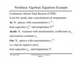
3 Nonlinear Control of the Magnetic Levitation System 3.1 System Dynamics Consider the following dynamic model of the magnetic levitation system shown in Fig. 19, where Fmag is de magnetic force, m is the levitated mass, g denotes the gravity acceleration, x is the levitation gap, i is the eletric current through the coil and Kmag is the magnetic parameter of the system.: m¨ x = mg − Fmag
(3.1)
2
Fmag =
Kmag i x2
(3.2)
Figure 19 – Magnetic Levitation System
In this dissertation, all stability proofs of control laws are proven considering an unbounded control and states. In practice, the magnetic levitation system has Fmag = Kmag i2 that can assume only positive values. The operating range is also bounded, since x2 the magnetic levitation system is defined only for positive gaps. This means that levitation overshoots are critical for the system operation. If a large overshoot occurs, the system will operate very near of x = 0. The operation very near the origin is sensible because x is measured through real sensors in a noisy setting. This fact can lead to instability, when the levitated mass "stick" to the coil. Otherwise, operating with a smaller x have the interesting advantage of less current consumption to generate the magnetic force. In this way, a judicious choice of the desired trajectory is required in order to balance stability and current consumption.
32
Chapter 3. Nonlinear Control of the Magnetic Levitation System
3.2 Tracking Control Law for the Nominal System Consider the following change of variables: θ=−
m Kmag
u=
i2 x2
(3.3)
The system dynamics can be written: θ(¨ x − g) = u
(3.4)
If the parameter θ is exactly known, one can consider the following tracking control law: u = θ(v − g) v = x¨d − λ2 x˜ − 2λx˜˙
(3.5)
xd is the desired trajectory, x˜ = (x − xd ) is the tracking error and λ ∈ R+ . While u can be considered the linearization control, v is the stabilization part related to pole placement. The resulting asymptotically stable linear error dynamics is shown below, leading x˜ → 0. This formulation results in two negative closed-loop poles equal to −λ. x¨˜ + 2λx˜˙ + λ2 x˜ = 0
(3.6)
The nominal control is projected for a perfectly known input gain θ. In practice, this parameter has a uncertainty margin and is slowly time-varying. This issue causes an imperfect linearization of the system, leading to poor tracking performance. One possible solution is adding an integrator in the feedback law, in order to eliminate the steady-state error and compensate the uncertain input gain. Although the control law is designed using the virtual control u, the real input of the system is the electrical current i: √ i=
ux2 , u ≥ 0
(3.7)
Since the system can not produce negative values of u (the magnetic force is always attractive), this variable always saturates on u = 0 before reaching negative values. In fact, when u = 0: θ(¨ x − g) = 0 , θ 6= 0 x¨ = g Which represents a free falling mass.
(3.8)
3.3. Feedback Linearization with Integrator
33
3.3 Feedback Linearization with Integrator Consider the parametric error θ˜ = θˆ − θ. Applying the linearization control with the estimated parameter: ˆ − g) θ(¨ x − g) = θ(v (3.9) The above dynamics can be identified as the nominal linearization control with an ˜ − g): additive parametric error contribution θ(v ˜ − g) θ(¨ x − g) = (θ + θ)(v
(3.10)
Rearranging terms, the resulting closed-loop dynamics are: θ˜ v+ x¨ − 1 + θ !
θ˜ g=0 θ
(3.11)
Differentiating once: θ˜ ... x − 1+ v˙ = 0 θ !
(3.12)
Considering the following stabilizing control which imposes three stable poles equal to −λ in the nominal system, where x˜ = (x − xd ) is the tracking error: v = x¨d − λ3
Z t 0
x˜ dt − 3λ2 x˜ − 3λx˜˙ , λ ∈ R+
... v˙ = x d − λ3 x˜ − 3λ2 x˜˙ − 3λx¨˜ �
(3.13)
(3.14) ˜
�
Substituting Eq.(3.14) in Eq.(3.12), where κ = 1 + θθ , the tracking error dynamics will be: ... ... x˜ + 3κλx¨˜ + 3κλ2 x˜˙ + κλ3 x˜ = (κ − 1) x d (3.15) ... where (κ − 1) x d is a transitory forced term because one wants to steer the system to ... a nominal gap where x d = 0. It is possible to analyze the system stability through Routh-Hurwitz criterion considering that the above equation is a forced third order linear system. The characteristic polynomial can be written as: a3 s 3 + a2 s 2 + a1 s + a0 = 0
(3.16)
The generic Hurwitz stability condition for a third order characteristic polynomial is an > 0 and a2 a1 > a3 a0 . Comparing with Eq.(3.15), we must have: 3κλ · 3κλ2 = 9κ2 λ3 > κλ3 , (λ > 0)
(3.17)
9κ2 > κ
(3.18)
κ(9κ − 1) > 0 1 κ < 0 or κ > 9
(3.19) (3.20)
34
Chapter 3. Nonlinear Control of the Magnetic Levitation System
Considering the first solution: θ˜ κ= 1+ θ 9
(3.24) (3.25) (3.26)
Eq.(3.26) shows the robust stability of the proposed control law when an integrator is included in the nominal control. The system is stable even when the real parameter is almost nine times the estimated parameter. Eq.(3.26) also shows that overestimating the magnitude of θˆ doesn’t affect the stability. An intuitive interpretation when the magnitude of θˆ is overestimated is that or m is overestimated or Kmag is underestimated, since m θ = − Kmag . This fact leads to an overcompensation in the control law, resulting in more magnetic force than is needed to follow the trajectory. If the situation were the opposite, the generated magnetic force could be insufficient to accelerate the mass and perform the tracking task. ... Although the stability proof through Eq.(3.26) considers the forced input (κ − 1) x d , ... the higher order term x d is usually transitory. In this work, the imposed trajectory will be a step filtered by a third order stable linear filter to ensure that the desired trajectory is of class C2 . The figures below show the experimental results of the proposed controller with the velocity estimation provided by a first order algebraic estimator Eq.(2.16) with an estimation window T = 0.01s and control poles defined by λ = 40. A complete description of the experimental setup can be found in Appendix A. The proposed control was able to provide a good tracking performance, despite the model uncertainties. In the second experiment, the measured gap x is filtered by a second order algebraic filter Eq.(2.24) with T = 0.01, while the algebraic derivative estimation still uses the raw
3.3. Feedback Linearization with Integrator
35
Figure 20 – Feedback Linearization + Integrator ×10-3
4.5
x xd
Position [m]
3 2.5 2
3.5 3 2.5 2
1.5
1.5 0
2
4 6 Time [s]
8
10
Figure 22 – Feedback Linearization + Integrator
0
×10-4
4
x ˜
2 1 0 -1
2
4 6 Time [s]
8
-2
×10-4
x ˜
3 2 1 0 -1 -2
0
2
4 6 Time [s]
8
10
Figure 24 – Feedback Linearization + Integrator
0
2
4 6 Time [s]
8
10
Figure 25 – Feedback Linearization + Integrator - Filtered x
0.65
0.65
i
i 0.6 Current [A]
0.6 Current [A]
10
Figure 23 – Feedback Linearization + Integrator - Filtered x
Tracking Error [m]
Tracking Error [m]
x xd
4
3.5
3
×10-3
4.5
4 Position [m]
Figure 21 – Feedback Linearization + Integrator - Filtered x
0.55 0.5 0.45
0.55 0.5 0.45
0.4
0.4 0
2
4 6 Time [s]
8
10
0
2
4 6 Time [s]
8
10
measured signal as in the previous experiment. No modifications were made in the control law. The experiment using the algebraic filter presents a smoother control signal (electrical
36
Chapter 3. Nonlinear Control of the Magnetic Levitation System
current) without loosing performance in the tracking task.
3.4 Lyapunov-Based Adaptive Control This approach was inspired by an adaptive control scheme of a mass on a frictionless surface presented in (SLOTINE; LI et al., 1991) and developed here for the magnetic levitation system. Instead of using the unknown parameter θ, use an initial estimation θˆ of the input gain in the nominal control law of Eq.(3.5). This choice results in the following dynamics, where w = (v − g): ˆ − g) = θw ˆ θ(¨ x − g) = θ(v
(3.27)
Subtracting θw and considering that θ˜ = (θˆ − θ) is the estimation error: ˜ θ(¨ x − g − w) = θw
(3.28)
Performing the change of variables: ψ = x˜˙ + λ˜ x
(3.29)
(¨ x − g − w) = (¨ x − g − x¨d + g + 2λx˜˙ + λ2 x˜) = ψ˙ + λψ
(3.30)
˜ θ(ψ˙ + λψ) = θw
(3.31)
Which leads:
Regarding that θ is a negative constant, one can consider the following positive definite Lyapunov function: ! 1 ˜2 1 2 (3.32) −θψ + θ V = 2 γ !
1 ˙ ˜ − ψθλ) + 1 θ˜θˆ˙ = ψ 2 θλ + θ˜ −ψw + 1 θˆ˙ V˙ = −θψ ψ˙ + θ˜θˆ = −ψ(θw γ γ γ
(3.33)
Considering the following parameter update law: ˙ θˆ = γψw
(3.34)
Substituting Eq.(3.34) in Eq.(3.33) is easy to see that V˙ = ψ 2 θλ ≤ 0. It’s possible to prove that ψ → 0 which is equivalent of x˜˙ → −λ˜ x. This way, the closed loop system tends to a first order stable dynamics, resulting in x˜ → 0 (tracking error converges to zero). Since the magnetic levitation system is very unstable, a high gain is needed to guarantee a fast parameter convergence and minimize the tracking error overshoot. After some point, increasing the gain is no longer interesting because of noise amplification.
3.4. Lyapunov-Based Adaptive Control
37
In the experimental tests, the adaptive gain used is γ = 8 × 10⁴ and the velocity estimation is provided by a first order algebraic estimator Eq.(2.16) with an estimation window T = 0.01s. Other controller parameters remain the same (Appendix A). Although the adaptive gain seems huge, it acts on the inverse of the magnetic parameter, where 2 1 = 0.625×10⁴ NAm2 . The proposed Lyapunov-based adaptive control shows an excellent Kmag0 tracking performance through the whole levitation path. The control signal is acceptable and the magnetic parameter convergence is fast, handling the initial parametric error. Considering a disturbance-free operation, the final magnetic force must be a simple compensation of the gravity effect (considering a steady state operation where (n) xd = 0, n > 0). The closed loop system is given by Eq.(3.27), Eq.(3.5) and Eq.(3.34): ˆ − g) θ(¨ x − g) = θ(v v = x¨d − λ2 x˜ − 2λx˜˙ ˙ θˆ = γψw
(3.35)
Since the control guarantees the elimination of the tracking error (˜ x → 0), v = 0 for constant trajectories. In the steady state, x¨ = 0 (constant trajectory). Replacing in Eqs.(3.35): ˆ θ(−g) = θ(−g) (3.36) θ = θˆ In this way, it can be shown that the parameter converges for the real value after the trajectory transient. Figure 26 – Lyapunov Adaptive ×10-3
3
x xd
Position [m]
4
Tracking Error [m]
4.5
Figure 27 – Lyapunov Adaptive
3.5 3 2.5 2 1.5
×10-4
x ˜
2 1 0 -1 -2
0
2
4 6 Time [s]
8
10
0
2
4 6 Time [s]
8
10
38
Chapter 3. Nonlinear Control of the Magnetic Levitation System
Figure 29 – Lyapunov Adaptive
Figure 28 – Lyapunov Adaptive 0.65
×10-4
1.6
i
Kmag Kmag [Nm2 /A2 ]
Current [A]
0.6 0.55 0.5 0.45 0.4 0
2
4 6 Time [s]
8
1.3 1 0.7 0.4
10
0
2
4 6 Time [s]
8
10
3.5 Least Squares Adaptive Control First, consider the nominal system dynamic: θ(¨ x − g) = u
(3.37)
The acceleration error can be written: u e = x¨ − g + = x¨ − g + βu θ �
�
(3.38)
Where β = − 1θ . Performing the minimization of the quadratic error over a sliding time window [t − he , t]: J=
Z t
e2 dt =
t−he
Z t
h
i
(¨ x − g)2 + 2(¨ x − g)βu + β 2 u2 dt
(3.39)
t−he
Z t h i ∂J 2(¨ x − g)u + 2βu2 dt = 0 = ∂β t−he
−
Z t
(¨ x − g)u dt =
t−he
Z t
(3.40)
βu2 dt
(3.41)
t−he
Considering that β is constant in the small time window [t − he , t]: βˆ =
Rt
¨)u dt t−he(g − x Rt 2 t−he u dt
(3.42)
t The above expression provides a fast parameter estimation when t−h u2 dt 6= 0. e To initialize the levitation, an initial magnetic parameter estimation Kmag0 is provided to the controller. This estimation is used in the feedback control law until least squares estimation (LSE) becomes non-singular. After this point, the least squares estimation (LSE) is used for feedback providing an online estimation θˆ = − β1ˆ of the real parameter θ in the nominal tracking control law of Eq.(3.5).
R
3.5. Least Squares Adaptive Control
39
Since u and x are noisy signals, the numerator and denominator of Eq.(3.42) are simultaneously filtered by some low pass filter. This filtering takes advantage of the rational form of the LSE, since the quotient will not be affected by the filters. For this purpose, 1 a simple first order low pass filter Q(s) = 0.05s+1 is used in this work. On the following notation, ξf (t) = Q(s)ξ(t) where ξf (t) is defined as the output of Q(s) when an input ξ(t) is applied to the filter. Hence the estimation of β may be rewritten as: t Q(s) t−h (g − x¨)u dt ˆ βf = Ret Q(s) t−he u2 dt
R
(3.43)
In the experimental tests, the estimation window is he = 0.08s and all the first and second order derivatives were provided by second order algebraic estimators, with T = 0.01 for first derivative estimation and T = 0.02 for second derivative estimation. Other controller parameters remain the same (Appendix A). Figure 30 – Least Squares Adaptive ×10-3
y yd
4 Position [m]
×10-4
3
3.5
Tracking Error [m]
4.5
Figure 31 – Least Squares Adaptive
3 2.5 2 1.5
x ˜
2 1 0 -1 -2
0
2
4 6 Time [s]
8
10
0
4 6 Time [s]
8
10
Figure 33 – Least Squares Adaptive
Figure 32 – Least Squares Adaptive
×10-5
0.7
i Kmag [Nm2 /A2 ]
0.65 Current [A]
2
0.6 0.55 0.5 0.45 0.4 0
2
4 6 Time [s]
8
10
16 14 12 10 8 6 4 2
Kmag
0
2
4 6 Time [s]
8
10
The proposed least-squares adaptive control shows an excellent tracking performance. It’s important to notice that the estimator used for the magnetic parameter is
40
Chapter 3. Nonlinear Control of the Magnetic Levitation System
independent of the control law and therefore could be used with other control approaches. In LSE, the magnetic parameter is directly estimated via input-output measures, while the Lyapunov adaptive control presented in the previous section depends on both the control law and the parameter update law.
41
4 Model-Free Control The Model-free control via algebraic techniques, introduced in (FLIESS; JOIN, 2008) and (FLIESS; JOIN, 2009) is an approach that aims the trivialization of nonlinear control, discarding the need of an accurate dynamic model. Several practical examples have been shown in the literature (FLIESS; JOIN, 2013). In this chapter, the main ideas of the model-free approach will be explained focusing on the implementation for the magnetic levitation system.
4.1 Ultra-local Model The main idea of model-free control is the substitution of the SISO dynamic system model by a generic ultra local model: y (ν) = φ + αu
(4.1)
• y (ν) is the ν-order derivative of y. The positive integer ν is selected by the practitioner. In the known examples, ν may be chosen to be 1, or seldom 2, to provide a good tracking performance. • φ represents the unknown parts of the plant, including possible disturbances. This effects are condensed in this single parameter, which is identified on real time through algebraic techniques due to (FLIESS; SIRA-RAMIREZ, 2004). Another possible approach is the determination of φ through algebraic derivative estimation ((MBOUP; JOIN; FLIESS, 2007)). • α ∈ R is a constant parameter chosen by the practitioner such that αu and y (ν) are of the same magnitude. This choice is obtained by trials and errors until a good closed loop performance is achieved. • The ultra-local model may be seen as an approximate dynamics valid in a short period of time. The online identification of φ allows a real time update of this model, which is used for control synthesis. This approach aims the simplification of nonlinear control by abandoning the need of a global and complex nonlinear model.
4.2 Control Law Assume that ν = 2 in Eq.(4.1): y¨ = φ + αu
(4.2)
42
Chapter 4. Model-Free Control
Closing the loop with a linearizing control including a Proportional-IntegralDerivative action: R −φ + y¨d − KI e − KP e − KD e˙ u= (4.3) α yd is the desired trajectory, e = y − yd is the tracking error and KI ,KP ,KD are the usual PID tuning gains. The resulting closed-loop dynamics will be:
e¨ + KI
Z
e + KP e + KD e˙ = 0
(4.4)
4.2.1 PD Tuning Choosing KI = 0, KP = λ2 and KD = 2λ, λ ∈ R+ results in a stable closed loop dynamics with two real negative poles equal to −λ: e¨ + λ2 e + 2λe˙ = 0
(4.5)
4.2.2 PID Tuning Choosing KI = λ3 , KP = 3λ2 and KD = 3λ, λ ∈ R+ results in a stable closed loop dynamics with three real negative poles equal to −λ: e¨ + λ
3
Z
e + 3λ2 e + 3λe˙ = 0
(4.6)
4.3 Online Identification of the Ultra-local Model Parameter 4.3.1 Identification through Algebraic Estimation (ALG) Applying the Laplace transform on the ultra-local model of Eq.(4.2), assuming that φ is constant in a short period of time: s2 Y (s) − sy(0) − y(0) ˙ =
φ + αU (s) s
(4.7)
Differentiating with respect to s in order to eliminate y(0): ˙ 2sY (s) + s2
d d Y (s) − y(0) = −1s−2 φ + α U (s) ds ds
(4.8)
Differentiating one more time with respect to s in order to eliminate y(0): 2Y (s) + 4s
d d2 d2 Y (s) + s2 2 Y (s) = 2s−3 φ + α 2 U (s) ds ds ds
(4.9)
Multiplying by s13 for the elimination of time derivatives and filtering, letting every factor be integrated at least one time1 : 2 1
1 1 d 1 d2 1 1 d2 Y (s) + 4 Y (s) + Y (s) = 2φ + α U (s) s3 s2 ds s ds2 s6 s3 ds2
In this context, the iterated integrals are low-pass filters which attenuate noises.
(4.10)
4.3. Online Identification of the Ultra-local Model Parameter
43
The terms containing the factor s1α are transformed to time domain using the relation: c tα−1 (4.11) , α ≥ 1 , c ∈ C ←→ c sα (α − 1)! Remembering that the differentiation of Y (s) with respect to s is related to a multiplication by −t in time domain and left multiplying Y (s) by s1α , α ≥ 1 corresponds to iterated integrals, the Cauchy formula for repeated integration is used to provide a dn closed-form expression for the operator s1α ds n in a single integral: 1 dn (−1)n Z t (t − τ )α−1 τ n y(τ ) dτ Y (s) ←→ α n s ds (α − 1)! 0
(4.12)
The resulting expression of Eq.(4.10) in time domain will be: φ=
30α Z t 60 Z t 2 2 (t − 6tτ + 6τ )y(τ ) dτ − (t − τ )2 τ 2 u(τ ) dτ t5 0 t5 0
(4.13)
The above expression can be digitally implemented resulting in a FIR filter. For this purpose, the method is modified and we integrate backwards in a small fixed window of length T to provide a feasible implementation in real-time, similar to the estimators presented in Section 2.4. In this particular case, φ is estimated as a time independent constant and therefore doesn’t shift it’s signal when estimated in a backward integration. After some change of variables, Eq.(4.14) is the final expression for the algebraic estimator of φ (ALG) : 60 Z T 2 30α Z T 2 φ= 5 (T − 6T τ + 6τ )y(t − τ ) dτ − 5 (T − τ )2 τ 2 u(t − τ ) dτ T 0 T 0
(4.14)
Each integral in this expression can be digitally implemented using the trapezoidal integration. Notice that the filter coefficients are independent of the current time t and can be computed a priori to reduce the computational effort. An efficient implementation of each integral is to store the pre-calculated discrete filter values in a vector (taking account the coefficients of trapezoidal integration). At each sample time, the buffer vector containing the samples of the last T seconds is multiplied by the filter coefficients vector resulting in the integral in the window T2 . To avoid an algebraic loop, the previous value of φ is used for the calculation of the actual control input in Eq.(4.3). In this implementation, the assumption that φ is constant is no longer a problem, since the estimation is made in a short sliding window T . If this were not the case, the estimator would have to be periodically reseted due to estimation drift. 2
see Section 2.4 for details of the digital implementation.
44
Chapter 4. Model-Free Control
4.3.2 Identification through Derivative Estimation (ACC) The unknown parameter φ can be estimated in real time using the acceleration estimation (ACC) through Eq.(2.49):
φ = y¨ − αu =
120 Z t 3 (4t − 45t2 τ + 108tτ 2 − 70τ 3 )y(τ ) dτ − αu t6 0
(4.15)
To avoid an algebraic loop in the digital implementation, the last control input is used to calculate the actual paramenter:
φ[k] = y¨[k] − αu[k − 1]
(4.16)
More details regarding to algebraic derivative estimation including digital implementation can be found in (ZEHETNER; REGER; HORN, 2007) and (MBOUP; JOIN; FLIESS, 2009). All the experiments were realized with a 10kHz sample frequency, control poles −40 defined by λ = 40 (both in PD and PID control) and levitated mass m = 0.240Kg (Appendix A). In the algebraic identification of φ through Eq.(4.14) a window T = 0.012s was used. y = x, where x is the levitation gap. The model-free control effort u = i, where i is the electric current in the coil. The desired trajectory xd was generated by a step on 8 t = 1s filtered by the third order filter (s+2) 3 to ensure that the desired trajectory is of class C2 . The first order derivative used in Eq.(4.3) is estimated through an algebraic derivative estimator. On the following experiments, ACC denotes the estimation of φ through acceleration Eq.(4.15) and ALG denotes the algebraic identification of φ Eq.(4.14). For each estimation method, a different value of α was tuned to provide a good response: αACC = −4400 and αALG = −50. The experimental results show an excellent tracking performance of model-free control, with a sightly better tracking when an integral action is included. The control signal was more noisy in the ALG scheme. Increasing the estimation window may increase the filtering properties, but the resulting estimation delay may lead to instability of the closed loop. The ACC scheme also have the estimation window of the second order derivative, leading to a different tuning of α for each scheme. Although model-free control presents a better performance, several tries were made to reach a good tuning in ALG and ACC schemes. The fact that the magnetic force 2 produced by the same current strongly varies with the levitation gap since Fmag = Kmag xi 2 may difficult the tuning of α, both in ALG and ACC schemes. Despite this fact, there is a considerably large range of values of α which results in good performance.
4.3. Online Identification of the Ultra-local Model Parameter
Figure 34 – Model-free (ALG+PD): Levitation Gap ×10-3
0.7
Position [m]
3.5 3 2.5
0.4 0.3 0.2 0.1
1.5
0 2
4 6 Time [s]
8
×10-3
4 6 Time [s]
8
10
0.7
3.5
u
0.6
y yd
4
3 2.5
0.5 0.4 0.3 0.2 0.1
2
0
1.5 0
2
4 6 Time [s]
8
0
10
Figure 38 – Model-free (ACC+PD): Levitation Gap
2
4 6 Time [s]
8
10
Figure 39 – Model-free (ACC+PD): Control Effort 0.7
×10-3
u
0.6
y yd
4 3.5
Current [A]
4.5
2
Figure 37 – Model-free (ALG+PID): Control Effort
Current [A]
4.5
0
10
Figure 36 – Model-free (ALG+PID): Levitation Gap
Position [m]
0.5
2 0
u
0.6
y yd
4
Position [m]
Figure 35 – Model-free (ALG+PD): Control Effort
Current [A]
4.5
45
3 2.5
0.5 0.4 0.3 0.2 0.1
2
0 0
1.5 0
2
4 6 Time [s]
8
10
2
4 6 Time [s]
8
10
46
Chapter 4. Model-Free Control
Figure 40 – Model-free (ACC+PID): Levitation Gap ×10-3
0.7
Position [m]
3.5
u
0.6
y yd
4
Current [A]
4.5
Figure 41 – Model-free (ACC+PID): Control Effort
3 2.5
0.5 0.4 0.3 0.2 0.1
2
0
1.5 0
2
4 6 Time [s]
8
10
0
2
4 6 Time [s]
8
10
47
5 Conclusions and Remarks Experimental results show that the algebraic derivative estimation is feasible and reliable when used as an observer in closed loop control. All the presented controllers had an excellent tracking performance. The Lyapunov-based adaptive control has a very similar performance compared to the least squares adaptive control. The Lyapunov-based control doesn’t need an estimation for the second order derivative and is easier to implement digitally. The model-free approach has a very good performance but needs more attention regarding parameter tunning. Due to different tuning parameters of the various controllers, it was very difficult to make a fair comparison between them. The advantage of the algebraic estimation method is that the estimation is purely based on algebra, avoiding the project of a nonlinear observer. Moreover, it provides a fast and precise estimation. The major drawback of the algebraic estimation is the need of high sample frequencies and the fact that the computational effort grows linearly with the filter’s window length, restricting the applications to fast hardwares. Fortunately, this is not an issue since nowadays fast hardwares are accessible and they are relatively cheap, indeed.
49
Bibliography DRAKUNOV, S.; UTKIN, V. Sliding mode observers. tutorial. In: IEEE. Decision and Control, 1995., Proceedings of the 34th IEEE Conference on. [S.l.], 1995. v. 4, p. 3376–3378. FLIESS, M.; JOIN, C. Intelligent pid controllers. In: 16th Mediterrean Conference on Control and Automation. [S.l.: s.n.], 2008. FLIESS, M.; JOIN, C. Model-free control and intelligent pid controllers: towards a possible trivialization of nonlinear control? arXiv preprint arXiv:0904.0322, 2009. FLIESS, M.; JOIN, C. Model-free control. International Journal of Control, Taylor & Francis, v. 86, n. 12, p. 2228–2252, 2013. FLIESS, M.; SIRA-RAMIREZ, H. An algebraic framework for linear identification. ESAIM controle optimisation et calcul des variations, EDP SCIENCES, v. 9, p. 151, 2004. KHALIL, H. K. High-gain observers in nonlinear feedback control. In: IEEE. Control, Automation and Systems, 2008. ICCAS 2008. International Conference on. [S.l.], 2008. p. xlvii–lvii. LEVANT, A. Robust exact differentiation via sliding mode technique. Automatica, Elsevier, v. 34, n. 3, p. 379–384, 1998. LUENBERGER, D. G. Observing the state of a linear system. Military Electronics, IEEE Transactions on, IEEE, v. 8, n. 2, p. 74–80, 1964. MBOUP, M.; JOIN, C.; FLIESS, M. A revised look at numerical differentiation with an application to nonlinear feedback control. In: The 15th Mediterrean Conference on Control and Automation-MED’2007. [S.l.: s.n.], 2007. MBOUP, M.; JOIN, C.; FLIESS, M. Numerical differentiation with annihilators in noisy environment. Numerical algorithms, Springer US, v. 50, n. 4, p. 439–467, 2009. MORAES, M. S.; SILVA, P. S. P. Algebraic derivative estimation and applications in adaptive control of magnetic levitation systems. In: 23rd ABCM International Congress of Mechanical Engineering. [S.l.: s.n.], 2015. MORAES, M. S.; SILVA, P. S. P. Model-free control of magnetic levitation systems through algebraic derivative estimation. In: 23rd ABCM International Congress of Mechanical Engineering. [S.l.: s.n.], 2015. SLOTINE, J.-J. E.; LI, W. et al. Applied nonlinear control. [S.l.]: Prentice-hall Englewood Cliffs, NJ, 1991. v. 199. ZEHETNER, J.; REGER, J.; HORN, M. A derivative estimation toolbox based on algebraic methods-theory and practice. In: IEEE. Control Applications, 2007. CCA 2007. IEEE International Conference on. [S.l.], 2007. p. 331–336.
Appendix
53
APPENDIX A – Experimental Setup
Figure 42 – Coil + Levitated Mass
Figure 43 – Experimental Setup Diagram The experimental setup used for control tests include a National Instruments PCI-6259 acquisition board working together with Matlab Realtime + Simulink Model. The power electronics receive the control signal and generate the electrical current in the coil, which is rolled on a ferromagnetic core. The levitation gap is measured through an optic sensor and the measure is sent back to the acquisition board.
54
APPENDIX A. Experimental Setup
The optic sensor was calibrated through a direct voltage measure for different gaps and the resulting curve was approximated by a linear fit. The gain from the acquisition board output voltage to the resulting current in the coil was also approximated by a linear regression. The inverse gains of the optic sensor and the power electronics were applied in the input and output of the acquisition board, respectively. This way, the control project can be made disregarding these gains. The dynamics concerning the coil inductance and the power electronics are disregarded, since these dynamics are much faster than the main dynamics represented by the system model. All the experiments were realized with a 10kHz sample frequency, an initial magnetic 2 parameter estimation Kmag0 = 1.6 × 10⁻⁴ NAm2 , control poles defined by λ = 40, levitated mass m = 0.240Kg and gravity acceleration g = 9.81 sm2 . The levitation always start with the mass supported on the aluminum base, without any levitation before the experiment (null initial coil current). Figure 45 – Optic Sensor - Linear Fit Operational Range
2.8
2.6
2.6
2.4
2.4
Voltage [V ]
Voltage [V ]
Figure 44 – Optic Sensor - Direct Measure
2.2 2 1.8
2.2 2
y = 0.129*x + 1.42
1.8
Measure Linear Fit
1.6
1.6 1.4 0
2
4 6 8 10 Distance [mm]
12
14
1.4 1
2
3
4 5 6 7 Distance [mm]
8
9