base on data from GTD–350 gas turbine, also calculated and measured ... high
efficiency of combined gas–steam installations (gas turbine of medium and high ...
Mechanics and Mechanical Engineering Vol. 15, No. 3 (2011) 207–216 c Technical University of Lodz ⃝
Algopithm for Design Calculation of Axial Flow Gas Turbine Compressor – Comparison with GTD–350 Compressor Design
Tadeusz CHMIELNIAK Sebastian LEPSZY Sebastian RULIK Institute of Power Engineering and Turbomachinery Silesian University of Technology
[email protected] [email protected] [email protected] Received (10 August 2011) Revised (25 September 2011) Accepted (28 September 2011)
The paper presents a simple algorithm for design calculation of axial flow compressor of gas turbine. The algorithm enables calculation of characteristic dimensions and gas angels in compressor stages using real gas model. Preliminary and detailed calculation base on data from GTD–350 gas turbine, also calculated and measured dimension of bleeds are compared. Keywords: Axial compressor, gas turbine, design
1.
Introduction
Continuous development of gas turbine technology is strongly connected with the aviation and power industry. The gas turbine cycles are usually designed for combustion of fossil fuels. However, it is also possible to replace the natural gas or petroleum with the renewable resources and biomass fuels [4]. The aim of many scientific researches in this area is to determine the optimal configuration of the thermal cycles with the external biomass combustion as well as development and tests of the gas turbine combustion chambers which can be adapted for the combustion of relatively low calorific value fuels and with low emission of pollutants [1,5]. The process of application of gas turbine based on biomass combustion is slow. The commercial gas turbine systems are not well available. Although, many small and large scale test gas turbine installations arise. The power generation units based on gas turbine have many advantages which in particular applications could be important. In case of installations with gas
Chmielniak, T, Lepszy, S, Rulik, S.
208
turbines the main advantages are: – high efficiency of combined gas–steam installations (gas turbine of medium and high power output); – fuel flexibility; – large quantity of high temperature heat; – low emission; – fast start–up process. The electricity production based on fuel from biomass in micro gas turbine installations may involve necessity of design new concepts of thermal cycles due to different fuel to air ratio (especially in case of low calorific gases). The new design concepts have to take into account also different working conditions of gas turbine based on the alternative fuels dedicated for electricity generation. The different working conditions during the year have to include partial loads, season work or peak loads. Moreover, quality and parameters of the specified fuel as well as additional heat generation adjusted to the requirements may have a great influence for the whole gas turbine system. The application of gas turbine based on alternative fuels in the industry may be especially interesting. This technology may be applied in sugar factory or corn and biomass driers. In these cases the large consumption of electricity and heat is desirable which is the advantage of the gas turbine technology. The important feature of gas turbine technology is the ability of design the installation which can work with almost every fuel type without limitations due to the octane or methane number or fuel temperature. The new and innovative concepts of application of gas turbine technology require development of new algorithms which can offer the calculation of thermodynamic and economy characteristics. The algorithms should take into account proper selection of necessary machine and devices which allows direct connection between the design calculations and economy analysis. Economic effectiveness is the main feature which decide about the implementation possibility of new energy technology. In order to obtain economic characteristic of systems with gas turbines the determination of compressor maps and main dimensions is necessary. In this paper the algorithm of the design process of the axial compressor for the gas turbine is presented. These program will be a part of a complex algorithm which covers the design and off design calculations of the main devices of the gas turbine installation. Applied non–dimensional model for preliminary calculations and 1-dimensional model for stage by stage calculations are so simple that it does not require the use of sophisticated computational techniques and at the same time allow to obtain the necessary data for further calculations of technical and economic characteristics. Results of compressor design presented in this paper base on parameters of GTD–350 helicopter turbine. 2. 2.1.
Compressor Design Algorithm Preliminary calculations
The preliminary calculations of the axial compressor allows to estimate inlet and outlet cross-section area and number of the compressor stages. The main input parameters are the air inlet temperature, pressure and mass flow, compression ratio,
Algopithm for Design Calculation of Axial Flow ...
209
isentropic efficiency and rotational speed. Tab. 1 presents the assumed input data for the preliminary calculation process. Table 1 Input data for preliminary calculations
Inlet total pressure Inlet total temperature Axial velocity Inlet velocity radial component Compression ratio Mass flow rate Isentropic efficiency Limited circumferential velocity of the blade tip Rotational speed
p01 , bar T01 , K ca , m/s cw1 , m/s p02/ p01 mp , kg/s ηi ut , m/s n, rev/s
The inlet pressure and temperature are assumed according to the ambient air parameters. The axial velocity for the axial compressor is in range 150–200m/s. This velocity is constant in compressor and for this reason this is one of most important assumption in design process using this algorithm. The assumed circumferential velocity of the blade tip is connected with the acceptable stress value in the blade or high Mach number which have a great influence for the flow losses. The impact of inlet guide vanes can be taking into account using inlet velocity radial component of air. The preliminary calculation algorithm is based on a few main steps [2, 3]: 1. Inlet static temperature and pressure calculations. 2. Inlet cross–section calculations. 3. Determine the characteristic inlet radius dimension. 4. Estimate outlet temperature and pressure. 5. Calculate characteristic outlet radius. 6. Preliminary estimation of the number of stages. Temperature rise in one stage of the compressor (constant mean radius) can be expressed as: λ · um · ca · (tan β1 − tan β2 ) (1) ∆T0S = cp Outlet angle is calculated using de Haller number defined as: H=
w2 w1
where w2,1 – relative stator air velocities, using the rule H>0.72. The number of stages in the compressor was estimated as follows:
(2)
Chmielniak, T, Lepszy, S, Rulik, S.
210
ls =
T02 − T01 ∆T0S
(3)
Output and input dimensions were calculated using continuity equation. To avoid excessive losses, Mach number at rotor tip should not exceed 1.1. The results obtained In case of preliminary calculations are presented in Tab. 2. Table 2 Preliminary calculation results
Compr. inlet Total temperature Total pressure Static temperatura Static pressure Density Outer blade radius Inner blade radius Inner to outer blade radius ratio Relative tip blade Mach number Mean radius Circumferential velocity on mean radius Temperature rise for one stage Estimated number of stages
T1 p1 ρ1 rt1 rr1 rr1 /rt1 M1t rm Um ∆T 0S ls
Compr. outlet T02 p02 T2 p2 ρ2 rt2 rr2 rr2 /rt2
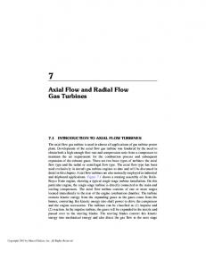
Stage number Figure 1 Work done factor in function of stage number
Algopithm for Design Calculation of Axial Flow ...
2.2.
211
Compressor stage design algorithm
The presented algorithm is able to calculate the basic flow and geometry parameters in specified cross–sections of the compressor as well as the power output and velocity triangles of the individual stages are calculated. The input data are similar to those assumed in case of preliminary calculations. Additionally, temperature rise and reaction of the stages was assumed. The mean temperature rise and number of stages was estimated on the basis of preliminary calculations. The work done factor λ which decrease the theoretical value of work carried out by fluid was taken into account. The work done factor is strictly connected with the non–uniform velocity profile in cross-section of the compressor. This parameter is a function of stage number (Fig. 1)[3] The basic relations applied in the presented algorithm include calculations of: – circumferential velocity component rise ∆cw =
cp · ∆T0S λ · um
(4)
– circumferential velocity component cw2 calculation: cw2 = cw1 + ∆cw
(5)
– β1 angle: ( β1 = arctan
um − cw1 ca
) (6)
– β2 angle: ( β2 = arctan
um − cw2 ca
) (7)
– α1 angle: ( α1 = arctan
ca cw1
) (8)
– α2 angle: ( α2 = arctan
cw2 ca
) (9)
– De Hallera number calculation for the rotor blade of the first stage Hw =
w2 = w1
ca cos β2 ca cos β1
=
cos β1 cos β2
(10)
Total pressure and temperature in the first stage outlet was calculated as follows: (
ηi · ∆T0S p03 = p01 · 1 + T01 T03 = T01 + ∆T0S
κ ) κ−1
(11) (12)
Chmielniak, T, Lepszy, S, Rulik, S.
212
Stage power output: Ns = mp · um · ∆cw
(13)
Calculations of next stages were differ in case of β1 and β2 angles: (
) ∆β1−2 + ∆β1−2 β1 = arctan 2 ( ) ∆β1−2 − ∆β1−2 β2 = arctan 2 ∆T0S · cp ∆β1−2 = tan β1 − tan β2 = λ · um · ca 2 · Λ · um ∆β1+2 = tan β1 + tan β2 = ca
(14) (15) (16) (17)
Additinally α1 and α2 angles are calculated as follow: (
) um − tan β1 ca ( ) um α2 = arctan − tan β2 ca
α1 = arctan
(18) (19)
Deflection of the rotor blades: D = β1 − β2
(20)
De Hallera number for the rotor blades of n stage: Hw (n) =
w2 (n) = w1 (n)
ca cos β2 (n) ca cos β1 (n)
=
cos β1 (n) cos β2 (n)
(21)
De Hallera number for the stator blades of n − 1 stage: Hk (n − 1) =
c3 (n − 1) = c2 (n − 1)
ca cos α3 (n−1) ca cos α2 (n−1)
=
cos α2 (n − 1) cos α2 (n − 1) = cos α3 (n − 1) cos α1 (n)
(22)
The n–1 stage outlet angle is equal to n stage inlet angle. Additionally, inlet total pressure p01 and total temperature T01 to the n stage is equal to the outlet total pressure p03 and temperature T03 in case of n-1 stage. Total pressure and temperature for the outlet section of n stage is expressed as follow: (
ηi · ∆T0S p03 = p01 · 1 + T01 T03 = T01 + ∆T0S
κ ) κ−1
(23) (24)
For calculation of compressor with constant outer diameter, for each stage different values of average circumferential velocity were assumed.
Algopithm for Design Calculation of Axial Flow ...
3.
213
Validation of the compressor design algorithm
The assessment of the presented algorithm was done on the basis of GTD-350 helicopter gas turbine design data. The selected gas turbine is a part of a test rig in the Institute of Power Engineering and Turbomachinery of Silesian University of Technology (Fig. 2). The turbine is connected with the eddy current brake. It allows to investigate the influence of different turbine loads for the main gas turbine parameters. The test rig is supplied by the aviation kerosene. Parameters of gas turbine at starting conditions were the source of data for preliminary design calculation (Tab. 3). Results of preliminary calculation are shown in Tab. 4.
Figure 2 Fotography of GTD–350 gas turbine test rig
Table 3 The main input data assumed for the calculations
Inlet total pressure Inlet total temperature Axial velocity – constant for all stages Outlet radial velocity Pressure ratio Inlet air mass flow Isentropic efficiency Limited circumferential velocity of the blade tip Rotational speed
p01 T01 ca cw1 mp ?is Ut n
1.01 288.00 151.00 20.00 5.60 2.19 0.85 305.2 720.00
bar K m/s m/s kg/s m/s obr/s
Chmielniak, T, Lepszy, S, Rulik, S.
214
Results of preliminary design are shown on Tab. 4 Table 4 The main preliminary design results
Total tempeature K Total pressure, bar Static temperature Static pressure Density Tip bled radius Hub blead radius Hub tip radius ratio Blead tip reative Mach number Mean diameter Bled Speed at mean diameter Estimated stage total temperature increase Estimated number of stages
Compressor inlet T01 288.0 p01 1.010 T1 287.8 p1 1.008 ρx 1.220 rt1 0.0675 rr1 0.0277 rr1 /rt1 0.410 M1t 0.949
Compressor outlet T02 513.91 p02 5.656 T2 502.56 p2 5.231 ρ2 3.627 rt2 0.0675 rr2 0.0572 rr2 /rt2 0.849
rm1 um1
0.0476 215.23
rm2 um2
∆T0S
19.57
ls
12
0.0623 276.54
For detailed calculation it was assumed that compressor has 11 stages and static temperature increase is equal in each stage. Reaction for first two stages was lower then 0.5. Selected results for first, seventh and eleventh stag are shown in Tab. 5. Table 5 The main design results for selected stages
Stage number Total inlet pressure, bar Total inlet pressure, bar Total inlet tempeature, K Total outlet tempeature, K β1 , deg β2 , deg α1 , deg α2 , deg Rotor de Haller number Stator de Haller number Work coeficient λ Deflection, deg Power, kW
1 1.010 1.247 288.0 309.00
7 2.988 3.463 414.0 435.00
11 5.186 5.656 498.0 512.71
51.81 32.98 0.00 31.89 0.74 0.89 0.97 18.824 47.719
44.43 16.22 16.22 44.43 0.74 0.74 0.87 28.203 52.866
41.41 21.26 21.26 41.41 0.80 0.86 20.159 37.823
Hub blead diameter, mm
Algopithm for Design Calculation of Axial Flow ...
215
120 100 80 60 GTD-350 dimension 40 Calcualted dimension 20 0 0
2
4
6
8
10
Stage number
Figure 3 Comparision of calculated and mesuered bled hub diameter
In the next step length of rotor bleeds were compared. This results are presented in Fig. 3. It can be seen that calculated and measured values are quite similar. This comparison is made only for first 7 stages because compressor from GTD–350 consist with seventh stages of axial compressor and on stag of centrifugal compressor. 4.
Conclusions
Presented algorithm allows calculation of main axial flow compressors parameters. Crucial advantages of presented algorithm is the possibility of calculations of relatives Mach number at blade tip and de Haller number in stators and rotors. Results obtained for modelling, based on GTD–350 parameters, corresponds with reference data of axial velocity and relative Mach number at bleat tip. Results of blades high calculations are comparable with GTD-350 blades high. Acknowledgements The results presented in this paper were obtained from research work co–financed by the National Centre of Research and Development and ENERGA SA in the Strategic Research Programme – ”Advanced technologies for energy generation” – ”Development of integrated production technology of fuels and energy from biomass, agricultural waste and others”. References [1] Cameretti, M. and Tuccillo, R.: Comparing different solutions for the micro–gas turbine combustor, Proceedings of ASME Turbo Expo 2004: Power for Land, Sea and Air, Viena, Austria GT2004–53286 ,2004. [2] Chmielniak, T., Rusin, A. and Czwiertnia, K.: Turbiny gazowe, Wydawnictwo Polskiej Akademii Nauk, Wroclaw, 2001. [3] Cohen. H, Rogers. G.F.C. and Saravanamuttoo, H.I.H.: Gas Turbine Theory, Biddles Ltd, Guildford and King’s Lynn, 1996.
216
Chmielniak, T, Lepszy, S, Rulik, S.
ahl, K. and Neergaardt, M.: IGCC Power Plant for Biomass Utilization, [4] St¨ V¨ arnamo, Sweden, Biomass and Bioenergy Vol 15, 3, p. 205–211, 1998. [5] Traverso, A. et al.: Demonstration plant and expected performance of an externally fired micro gas turbines for distributed power generation, ASME, Paper GT 2003– 38268, 2003.