Multiple-input multiple-output (MIMO) wireless communi- ... and at the receiver to increase system capacity and to achieve OFDM modulation at the transmitter ...
Algorithm and VLSI Architecture for Linear MMSE Detection in MIMO-OFDM Systems A. Burg, S. Haene, D. Perels, P. Luethi, N. Felber and W. Fichtner Integrated Systems Laboratory, ETH Zurich, Switzerland { apburg,haene,perels,luethi,felber,fw } @iis.ee.ethz.ch Abstract- The paper describes an algorithm and a corresponding VLSI architecture for the implementation of linear MMSE detection in packet-based MIMO-OFDM communication systems. The advantages of the presented receiver architecture are low latency, high-throughput, and efficient resource utilization, since the hardware required for the computation of the MMSE estimators is reused for the detection. The algorithm also supports the extraction of soft information for channel decoding. I. INTRODUCTION
Multiple-input multiple-output (MIMO) wireless communication systems [1] employ multiple antennas at the transmitter and at the receiver to increase system capacity and to achieve better quality of service. In spatial multiplexing mode, MIMO systems reach higher peak data rates without increasing the bandwidth of the system by transmitting multiple data streams in parallel in the same frequency band. Orthogonal frequency division multiplexing (OFDM) is a modulation scheme that is robust against interference arising from multipath propagation. Consequently, many upcoming standards for high throughput wireless communication such as IEEE 802.1 in and IEEE 802.16 rely on a combination of MIMO with OFDM. Unfortunately, the performance improvements of MIMO technology also entail a considerable increase in signal processing complexity, in particular for the separation of the parallel data streams. Hence, a major challenge associated with the implementation of future wireless communication systems is in the design of low-complexity MIMO detection algorithms and corresponding VLSI architectures. In this work, we consider the VLSI implementation of linear MMSE detection for wideband MIMO-OFDM systems. A suboptimal linear detection scheme is contemplated since the implementation of algorithms with better performance (e.g., [2], [3], [4]) either do not meet the high throughput requirements for MIMO-WLAN (especially not on FPGAs) or lack the ability to provide soft-information for channel decoding with low hardware complexity. A. System Model and Requirements The system under consideration is a packet-based MIMOOFDM system wtth MT transmit and MR recetve antennas.
0-7803-9390-2/06/$20.00~~~lem ©2006 IEEEn
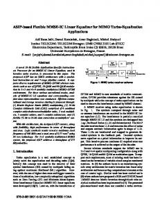
Data frame
Dtat
Idle
Idle
MIMO detectioni
Detection latency
Fig. 1. Timing diagram of MIMO detection process in packet-based MIMOOFDM systems.
time index t on the kth tone of the OFDM signal. After proper OFDM modulation at the transmitter and demodulation at the receiver, the corresponding received vector y[k, t] is given by y[k, t]= H[k]s[k, t] + n[k, t], (1)
where the MR X MT-dimensional matrix H[k] describes the effective MIMO channel for the kth tone and the vector n[k, t] models the thermal noise in the system as i.i.d. proper complex Gaussian with variance (Y per complex dimension. Assuming knowledge of the channel matrices, the linear MMSE estimator for each tone is given by
G[k] = (HH [k]H[k] +MT
2I) l HH[k]
(2)
and linear MIMO detection corresponds to a straightforward matrix-vector multiplication according to s[k,t] G[k]y[k,t] (3) followed by quantization of the entries of s[k, t] to the nearest constellation point. The difficulty in the implementation of linear receivers for packet-based MIMO-OFDM systems arises from the frame structure because the initial training phase, during which the receiver obtains knowledge of H[k], is immediately followed by data. Since the detection of the data according to (3) only starts when the MMSE estimators for all K data carrying tones have been computed, the delay incurred by the preprocessing according to (2) translates directly into detection latency as illustrated in Fig. 1. In MIMO-OFDM receiver implementations [5], this latency is responsible for considerable memory to buffer the received vectors and can cause probrequirements par than
4102emnt
Authorized licensed use limited to: Texas A M University. Downloaded on March 24, 2009 at 03:08 from IEEE Xplore. Restrictions apply.
th-eA
acsscnto ISCA 2006du
of packet-based MIMO-OFDM receivers. However, it is also noted that the corresponding operation is only performed once at the start of the frame so that, without special provisions, the potentially costly hardware for the preprocessing will be idle most of the time. Contribution: In this paper an algorithm for efficient toneby-tone linear preprocessing of channel state information in MIMO-OFDM systems is presented, together with a hardwareefficient VLSI architecture for its realization. The described receiver constitutes the basis for the soft-output demapper described in [6] which yields a 5-6 dB gain in terms of signal to noise ratio (SNR) over a hard-decision MMSE decoder. The reported ASIC and FPGA area and performance figures provide reference for the true silicon complexity of linear MMSE receivers for MIMO-OFDM systems. Outline: The next section introduces the algorithm for the computation of the linear MMSE detectors. Section III describes a scalable VLSI architecture for the proposed algorithm. Area and performance figures for ASIC and FPGA implementations are provided in Section IV. Section V concludes the paper.
number of multiplications2 and divisions is given by 5 2 CMult =2MRMT + 5MRM -MT +MT
2T5
CDiv2MR
(6)
In order to map recursion (5) to hardware, its compact mathematical description is expanded as shown in Alg. 1. The operation sequence is designed to reduce the dynamic range of intermediate results and to minimize the number of costly divisions, while keeping the number of multiplications low.
Algorithm 1 Algorithm for computing the MMSE estimator 1l I P(M) for MT6M MR do 2lfrj=I... g =P(j-i)HH 3 S= 1 + Hj (note that S is strictly positive) 4: 5: Se elog25S - 2Sel/ g = 5mg 6: 7: p(j) = p(j-1) - ggH2-Se
8: end for 9: G =P(MR)HH
III. VLSI ARCHITECTURE
II. PREPROCESSING ALGORITHM
The choice of a suitable hardware architecture for the Algorithm choices for the implementation of (2) are either based on QR-decomposition [7] using unitary transformations implementation of Alg. 1 depends on the system specifications or on direct matrix inversion algorithms with conventional and on the available area: The most area efficient solution arithmetic. The main advantages of the QR approach lie in its is a fully decomposed, processor-like architecture. However,
favorable numerical properties in fixed-point implementations such a minimum-area solution cannot meet the low-latency and in the availability of a wide range of regular array archi- requirements of MIMO-OFDM systems. A highly parallel tectures [8], [9] for their implementation. The main arguments architecture achieves higher throughput but suffers signififor direct matrix inversion are the lower number of operations cantly from the fact that data dependencies and the desire compared to QR decomposition and the fact that the matrix for a regular data flow mandate a sequential execution of the (HH [k]H[k] +MTG2I) I is produced as an intermediate result. individual steps in Alg. 1. Since these steps differ significantly In fact, the diagonal entries of this matrix are required for the in the number of required operations, a massively parallel architecture would result in a poor utilization of processing computation of soft-outputs [10], [6]. resources. In a moderately parallel VLSI architecture the The implementation that is described in this paper relies number resources is chosen so that their average tp nAl.1rqieete on direct matrix inversion. The corresponding algorithm iS utlzto.of processing shg.Moto.h in borrowed from the updating procedure of the Kalman gain Hence, choosing Kalman filtering applications. The basic idea is to start from MT or a multiple Of MT multiplications. the trivial inverse Of and to obtain (HHH + MTG2I) 1 an MT-fold degree of parallelism leads to a high hardware utilization. through a series of MR rank-one updates by using the matrix inversion lemma. The iteration is initialized by setting A. Moderately Parallel Architecture The high-level block diagram of the proposed moderately 1 I (4) parallel architecture is shown in Fig. 2. The circuit employs p(O) MTG2 MT identical processing elements (PEs) arranged in a circular array and a common 1/ Y-block that computes the additions in and proceeds by computing step 4) and the pseudo floating-point division in step 5). The connections in the array are local, meaning that only neighHH p(j-l)' (5) boring PEs are connected with each other. Each PE mainly p(i) =p(i-1) contains a complex-valued multiplier, an adder and some local 1 + HHP(j-1)HH'i V storage registers as shown in Fig. 3. All intermediate variables where H1 denotes the jth row of H. After MR iterations, are stored locally, equally distributed over the PBs. For the
MT.2I
M
HI iH.Pi
p(MR)~~~~~~~~~~
HH+MGI (R n H
hr
h
. index of the OFDM tone has been omitted for brevity. The complexity of the above described algorithm in terms of the
21n
terms of complex-valued multiplications. The few real-valued mul-
tiplications are counted as complex-valued, assuming a dedicated VLSI architecture with multipliers optimized for complex-valued coefficients.
4103 Authorized licensed use limited to: Texas A M University. Downloaded on March 24, 2009 at 03:08 from IEEE Xplore. Restrictions apply.
Fr s r ' X S r fl X r wr wr tm ~ ~ ~ ~ ~ Cycles PE(1) PH'l
27 t | zt
z t|
4P4,2"j 2
P3,3
P2,4
[PHj]I
PE(3) _31 jl+22j2+l3j3