849
IEEE TRANSACTIONS ON COMPUTERS, VOL. 43, NO. 7, JULY 1994
Algorithm-Based Fault Tolerance for FFT Networks Sying-Jyan Wang and Niraj K. Jha Absfmct- Algorithm-based fault tolerance (ABFT) is a low-overbead system-level fault tolerance technique. Many ABFT schemes have been proposed in the past for fast Fourier transform (FFT) networks. In this work, a new ABFT scheme for F m networks is proposed. We show that the new approach maintains the high throughput of previous schemes, yet needs lower hardware overhead and achieves higher fault converge than previous schemes by .IOUet aL and Tao et aL
Index Terms- Algorithm-based fault tolerance, concurrent error detection, fast Fourier transform, hardware redundancy schemes, transient errors.
I. INTRODUCTION The fast Fourier transform (FFT)plays an important role in digital signal processing because it increases the computing efficiency for obtaining large discrete Fourier transform (DFT) dramatically [ 11. One of the most obvious ways of implementing the N-point FFT in hardware is to construct log, N stages of two-input N / 2 butterflies. Such a circuit will be called the FFT network [2] hereafter in this work. FFT networks are attractive because of their optimal performance (area . time’) and throughput. Three different schemes have been proposed for fault-tolerant FFT networks. Choi and Malek proposed a fault tolerance scheme for FFT based on recomputation through an alternate path [3]. The throughput of this scheme is only 50% compared to a system with no fault tolerance. In [4], Jou and Abraham proposed an ABFT scheme for FFT networks. The hardware overhead of this scheme is approximately 2/ log, N. Due to round-off errors, this scheme’s fault coverage or throughput or both may not be very satisfactory [5]. To deal with such a problem, an encoding scheme was suggested in [5] which achieves higher fault converge. Another scheme with a much weaker fault model was given in [6]. In this work, we propose a new algorithm-based concurrent errordetecting scheme for FFT networks, which has lower hardware overhead and achieves higher fault coverage than the schemes in [4], [5]. In the next section, we give some background information which is needed in the discussion later. In Section 111, we propose a new ABFT scheme for FFT networks and prove the correctness of this scheme. Next in Sections IV and V, we compare the performance and hardware overhead of this scheme with those of [4] and [5]. We conclude in Section VI. 11. PRELIMINARIES
In this section we present some preliminary concepts. A. An FFTNetwork
The discrete Fourier transform (DFT) of a sequence ~ ( pis) N-1
X ( k ) = Cz(p)W?,
k=O,l,...,N-l
(1)
p=o
Manuscript received April 9, 1992. This work was supported in part by ONR under contract “14-91-J-1199 and in part by AFOSR under contract AFOSR-90-0144. This work is based on “Algorithm-based fault tolerance for FFT networks,” by S.-J. Wang and N. K. Jha which appeared in the Proceedings of the International Symposium on Circuits and Systems, San Diego, CA, May 1992, pp. 141-144. S.-J. Wang is with the Institute of Computer Science, National ChungHsing University, Taichung, Taiwan 40227, R.O.C. N. K. Jha is with the Department of Electrical Engineering, Princeton University, Princeton, NJ 08544 USA; e-mail;
[email protected]. IEEE Log Number 9212768.
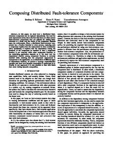
Fig. 1.
An 8-point FFT network
c =a
+ bWk
d = a - bWk
b
Fig. 2. A butterfiy module.
where WN = e-](,*”) is the Nth root of unity. In order to simplify the notation, where unambiguous, hereafter we write W k in place of W k . The N-point FFT networks considered in this work consist of (N/2) x log, N two-input butterflies, where N = 2”. An %point FFT network is shown in Fig. 1, and the function of each butterfly is shown in Fig. 2. The upper and lower input port of a butterfly module will be called port 0 and port 1, respectively. Each butterfly module with inputs a, b, and outputs c, d , performs the butterfly computation c = a + b x W k , d= a -
b x Wk
where W k is sometimes called a “twiddle factor.” The output sequence X ( k ) , O 5 k 5 N - 1, is given in bit-reversed order. In other words, X ( k ) will appear at output port h, where h = B R ( k ) , as defined next. Suppose the binary expansion of k, 0 5 k 5 N - 1, is klk, kn (this is equal to k12”-l k22n-2 ... kn), then the bit-reverse of k , denoted as B R ( k ) , is equal to k,kn-l . . . k l . The stages in an FFT network are labeled from 1 to n, and in each stage the butterflies are labeled from 0 to N / 2 - 1,from top to bottom. From now on, the Zth butterfly in stage i will be called butterfly ( i , I ) . The twiddle factor associated with butterlly ( i , 1 ) can be computed as follows. Let the binary expansion of Z be 1 Z2 . . In- 1. The following lemma follows from the description given in [7] (hereafter, we will sometimes use mixed binary-decimal representations of numbers for convenience). Lemma I: The twiddle factor associated with butterlly (i,Z) is W ” , where m = (1n-1Zn-2...ln--z+l) x 2n-a for i > 1, and m = O f o r i = 1. - e .
+
+ +
B. Fault Model In this work, we assume the module-level fault model [4]. When a fault appears in a butterfly, the resulting error can be modeled as an additive error at one of the input or output ports of the module, for example, at input ports a or b, or at output ports c or d of the butterfly in Fig. 2. Since in an FFT network an output port of a
0018-9340/94$04.00 0 1994 IEEE
850
IEEE TRANSACTIONS ON COMPUTERS, VOL. 43,
NO. 7, JULY
1994
Proof: If output port k is affected by fault fj, then klk2*-.kt = jn-z+~jn-l+z...jn (by Lemma 2). The path from f j to output port k enters stage s,i < s, at 1, position js-zjs-2+1...jnkz+l~l+~...ks-l(if s = i the position simply becomes j1j2 . . .jn). This can be Thus the path written as js-,js-2+l...jn-,klkz...k._l. passes through module js--r+ljs-z+~ .--jn--rk~kz**.ks--l, whose location is (s, cy), where a is the decimal equivalent of js-l+ljs-l+~...jn-lk~k2...k~-l.By Lemma 1, the
+
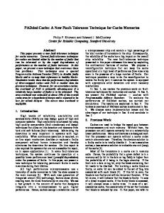
Fig. 3. A general CED scheme.
module is connected to only one input port of the next-stage module, faults on these ports are not distinguishable and will be considered as the same fault in the following discussion. For an FFT network of size N = 2", a fault at output port j of a stage i module is denoted by f f , 1 5 i 5 n, while a fault at input port j of the FFT network is denoted by f:. Examples of faults in a network of size 8 are given in Fig. 1.
twiddle factor associated with the module is W m s ( k ) where m,(lc) = ( k s - ~ k , - z ~ - - k xl )2"-". Since the path enters the module at input port js-tand leaves at output port k,, it is easy to see that the error is amplified by a factor ( - l ) 3 s - r t s ( W m s ( k ) ) 3 s - a in this stage. Thus E k can be written as the product of the initial error e and the gains of the successive stages after the fault site. Thus,
n n
G k ( f , ' )=
(-1)3a-*ka(Wm8(k))3 8 - 1 .
s=*+1
111. THE CONCURRENT ERRORDETECTION SCHEME
A. The Basic Scheme The discrete Fourier transform given in (1) can be written as
C. Data Path and Transfer Function
A general CED scheme is shown in Fig. 3. The inputs are encoded and outputs are decoded separately, and the results are compared to decide if the outputs are erroneous. Suppose a fault ff causes an additive error e. This error propagates through the FFT network and eventually causes an additive error E k at output port k of the network (some E k S may be zero, depending on the location of the fault). The final output error E , which appears at the output of the output detector, depends on all E k S as well as the decoding scheme. The g h at output port k, denoted as Gk(ff), is defined as Ek/e. The transfer function Sf is defined as E / e . Clearly, Sf should not be zero for any i,j, otherwise some faults may remain undetected. To compute each E k for a given fault fj, we have to find the data path from the fault site to output port k. Note that the topology of the FFT network is the same as that of an Omega network 171. For an Omega network of size N = 2", the path from input port S = slsz--.snto output port D = dld2...dn,sz,drE ( 0 , l},1 5 i 5 n, can be computed as follows. In stage i, the path starts at position sIs2+1..-snd1dz-*.dz-1, goes through a perfect shuffle and ends up in position s,+ls,+z -..s,d1dz.-.dz--1sl.The path passes module sz+1st+2 .-.sndl.--d,-1,entering the module at input port sl and leaving the module at output port d,, which corresponds to position s1+1s,+2 .s,dld. . .d,-ld, [8]. Lemma 2: A fault fj, with the binary expansion j = jljz can affect 2"-' output positions, whose port numbers begin with (jn--,+ljn--r+z.. .jn) x 2"-' and end with (jn--r+ljn--r+2. . .jn) x 2-1 + 2n-1 - 1. Proof: Suppose a fault ff causes an error at the corresponding location. After the error passes through the next stage, stage i 1, positions j Z j 3 . . - j n O and j 2 j 3 ' * . j n l are affected, which can be thought of as locations for two new faults in stage i 1. By repeating this process n - i times, i.e., until the output ports of the FFT network are reached, there could be 2"-' positions contaminated with errors, which start at position jn-l+ljn-t+~...jnOO..O (last n - i bits are Os) andend atpositionjn--r--ljn--2-~...jnll...1. Lemma 3: Suppose output port k = kl kp.. .k, is affected by a fault ff. Then the gain at port k is e j , ,
+
+
n
G k ( f *-) 3
(-l)3s--rks(Wms(k))3s--r
-
s=z+1
where m,(k) = (ks--lks-z--.kl) x 2"-".
Then (2) can be written as
2T=~N*~T
(3)
where * denotes matrix multiplication and T denotes transpose. The system-level encoding is done as follows. First, we define the row weight vector as
where W: = e - 3 ( 2 s q / 3 ) . Now letting
d s = r', * A , = ( w s ( O ) , w s ( l ) , . . . , w ~ ( N - 1 ) ) and augmenting the AN matrix by adding one more row ds,we have
[X ( N )] 2?T
["I
= 5s
*f
(4)
From (4) we note that
x ( N ) = G ~ * ~=
( T ~ * A N ) * z ~
= Fw * ( A N * ZT)= r', * d T . If the FFT network is fault-free, we should have X ( N ) = r',* d T . The CED scheme comprises of an encoder, a decoder and a TSC comparator. The input encoder generates input weighted check-sum
EEE TRANSACTIONS ON COMPUTERS, VOL. 43, NO. 7, JULY 1994
85 1
m Comparator
A
A
Fig. 4. The weighted checksum CED scheme for an 8-point FTT network.
WCS, = 5 s * ZT and the output decoder computes WCS, = r', * 2T.WCS, and WCS, are then compared by the TSC comparator to decide if they are equal. The scheme is illustrated in Fig. 4 for an 8-point FlT network. The encoder and decoder can be obtained from the above equations. At the output side, note that N-1
X ( N ) = r;u * rlT =
W,BR(k). X ( k )
Pro08 Since output port k = k l k 2 . . - k n contains an error due to the fault f f , by Lemma 2, we have kl k2 k, = jn--r+1jn--l+2 ....in.Given that j = j 1 j 2 . .jnis even, j , is zero and thus k, is zero. Let j ' = j 1 and let j ' be represented as j ; j ; . - - A ,then jk = j , for 1 5 m < n, and jh = 1. By Lemma 2, port k 2"-' will be affected by fault fi+l. Let k' = k 2"-' and let it be represented as k; k; . ..k h , then we have ki = kI for all 1 5 I < n and I # i , and k, = 0 , k : = 1. By Lemma 3 e . .
+
+
+
n
k=O
Gk,(f3,) =
N-1
w,"
=
*
X(BR(h)).
fl
(-l)J:-~k~(Wma(k'))3:-*.
(5)
s=r+1
~
h=O
c w," .
where SUM, =
+ 1, we have
m , ( k ' ) = ( k : - l k : - 2 - - - k : )x 2"-"
+ 2*-'
= ( k s - l k a - 2 . . .k l ) x 2"-"
x 2"-"
because k, = 0 and ki = 1.
N-1
X ( N )=
k ; ) x 2"-" and s 2 i
Since m , ( k ' ) = (k:-lk:-2...
In other words, at output port h the output X ( B R ( h ) )is multiplied by W ) . Since W ) = W!m0d3,and W," = 1, in fact, there are only two complex numbers in r', (namely, W,' and W:). Thus, the equation can be rewritten as
(Wms(k') )J : - , = ( w ~ , ( L ) + ~ ~ + ~ - ~ - ~ ) J : - ,
X(BR(h))
O