TBO. (time between outputs) is the elapsed computing time between successive algorithm outputs when the. AMG is operating periodically at steady-state.
L
--_
..........
+
......................
NASA
Contractor
Algorithm
Report
4339
to Architecture
Mapping
Model
(ATAMM)
Multicomputer
Operating
Functional
System
Specification
,-+l +__
R. Mietke, S. Som,
J. Stoughton, R. Obando,
M. Malekpour,
and
B. Mandala
COOPERATIVE AGREEMENT NOVEMBER 1990
NCC1-136
I-II:T_T .............. ii__--:i-i
+ .................
Uncl HI/33
0311983
as
++
--r
, .....
.... _--7
.....
........
_ T
E
-_ --_ 7------
+
_+__
+
+
z ............
+
_-27--_-_ - ....
+_
_+
+
.......
--
--_ -- _
_
m
._+
----
m
_+
L
--
....
_
.....
_
........
T-:
L
NASA
Contractor
Algorithm
Report
to Architecture
Mapping
Model
Multicomputer
S. Som,
R. Obando,
Dominion
Norfolk,
Prepared Langley under
Specification
J. Stoughton,
M. Malekpour, Old
and
B. Mandala
University
Research
Virginia
for Research Cooperative
Center Agreement
N/ A National Aeronautics and Space Administration Office of Management Scientific and Technical Information Division
1990
(ATAMM) Operating
Functional
R. Mielke,
4339
NCC1-136
Foundation
System
TABLE
I.
INTRODUCTION
II.
THE
III.
PERFORMANCE
ATAMM
III.i 111.2 III.3 IV.
AMOS
V.
AMOS
.................................................... MODEL
.................................................
ANALYSIS
AND
Performance Graph ATAMM
Measures
.................................
12
..................................
13 14 19
ADM ..................................
31
ADM Description ....................................... AMOS Description. System Capabilities ...................................
31 32 39
ENHANCEMENT
V.I V.2
DESIGN
4
Play and Resource Requirements .................. Performance Plane ...............................
IMPLEMENTATION
IV. 1 IV. 2 IV. 3
OF CONTENTS
IN
FOR
THE
THE
GVSC ...................................
Multiple
Concurrent
Multiple
Graph
Instantiations
Strategies
of
Node
Operations.
.............................
43 49
Parallel Strategy ............................................... Time Multiplexing Strategy ...................................... Priority Interrupt Strategy .....................................
52 56 58
V.3 V.4
59 63
Distributed Fault
Fault
Detection
Damage System System
Sources
Tolerant
and
Sinks .........................
Strategies
.............................
.................................................
64 66 66
Assessment ............................................... Recovery ................................................. Return to Service ........................................
67
REFERENCES
68 LIST
Algorithm 2
40
ATAMM
node
marked marked
graph graph
OF FIGURES
for
discrete
model
system
equation
..........
................................
ATAMM computational marked graph model for discrete system equation ..............................................
0U l
pR_CEDiNG
PAGE
BLA_'_?( NO'f
8
I0
iii
a ..ll_JNImIL
6
FILMED
TABLE
OF CONTENTS
LIST
(continued)
OF FIGURES
(continued)
Figure 4
ATAMMmodel
5
AMG
for
performance
6
CMG
for
Figure
7
SGP
diagram
for
Figure
5 .....................................
18
8
TGP
diagram
for
Figure
7 with
20
9
ATAMM
components
Ii
.......................................
example
..................................
16
5 .............................................
performance
plane
TBO
15
- 2 ........................
22
......................................
23
i0
Injection
II
ATAMM
12
Modified
AMG
for
Figure
5 ....................................
28
13
Modified
CMG
for
Figure
12 ...................................
29
14
(a) TBO
control
implementation
performance
plane
for
.............................
Figures
5 and
12 .................
SGP diagram and (b) TGP diagram for Figure 12 with - 2 ......................................................
25
30 33
15
Advanced
16
Major components of the ATAMM Multlcomputer Operating System (AMOS) ................................................
36
17
AMOS
37
18
(a)
19
Generic
VHSIC
20
The
NMG
for
21
AMG
example
22
(a) SGP diagram (b) TGP diagram for TBO - 2 for the AMG of Figure 21 .................................................
48
23
Enhanced
21 ........................
50
24
Ideal
the
51
25
A
26
Parallel
Development
functional Simplex
CMG
unit
and
(b)
the to
TMR
AMG
node
illustrate
the
AMG
of
improvement algorithm
execution
strategy
.....................
........................... pair
Computer ATAMM
the
System
diagram
enhanced
for
of
(ADM)
state
Spaceborne
throughput
collection
Module
representation
(GVSC)
System
.........
..............
model ......................... enhanced
Figure using
graphs for iv
ATAMM
model
enhanced
...........
ATAMM
Model..
(G) ......................... multiple
graphs
..............
41 42 45 47
m
53 55
TABLE LIST
OF
CONTENTS
OF FIGURES
(concluded) (concluded)
Figure 27
Time
28
Control
29
Modified
3O
AMOS
multiplexing
strategy
for
multiple
graphs
...............
57
strategy
for
GVSC ....................................
6O
Examine
and
Execute
62
fault
management
states
process
for
V
for
GVSC .................
GVSC .......................
65
ALGORITHM
TO
MULTICOMPUTER
ARCHITECTURE
OPERATING
SYSTEM
I.
The
purpose
Multicomputer
computer
is
first
an
on
the
second
Generic processor
Module
instruction AMOS periodic
is
architectures. where
vertices
data
sets
describe
acronym
ATAMM
model
which on
four
1750A AMOS
is
ATAMM
based
the
architecture processor.
developed a
rules. for
set
being
flow
Operating
processor
(GVSC),
also
data
developed
instruction is
To
describes
a
the
been
ATAMM
Algorithm
Multicomputer
has a
the
for
implements
Computer
special of
purpose
for
the
spaceborne
on
represent operands_
operating
decomposed
real-time An
or
SPECIFICATION
the
VHSIC
four 1750A
architecture. a
in
(ATAMM)
algorithm
AMOS
of
which
execution
algorithms
graph
VHSIC
Spaceborne
set
marked
(ADM),
version
breadboard
an
which of
to
ATAMM,
the
system
version
generation
is
decomposed
Westinghouse
VHSIC
a
AMOS,
Development
based
is
a
operating
generation
Advanced
A
of
architecture.
System, A
Model,
implementation
FUNCTIONAL
document
System.
Mapping
MODEL
INTRODUCTION
this
Operating
Architecture the
of
MAPPING
signal
on
algorithm
It
a is
algorithm is
system processing
variety expressed
of as
operations assumed
suitable
that
and the
a
and
for control
multicomputer directed edges
graph represent
algorithms
are
decision-free absence
and
of
large-grained.
data
dependent
representation. time to The
to
time
functional of
units
centralized
relation
to
is
and
from
one
a
is
and
common
an
global
is
to
of
two each
memory.
the
another. or
more
having
memory
directed
bus.
which of
by
a
Functional
interconnecting
Coordination
flow
graph
compared
node
resources,
the
that
large
consist
through
distributed. control
assumption
graph
to
computing
other
the
to
algorithm
operations
communication each
refers
the
to
assumed
or
share
or
data
data
units
with
functional
either
move
processing,
communicate
The
to
in
refers
algorithm
architecture
capability units
perform
required
computer
identical
paths
Large-grained
required the
Decision-free
a
may
be
resources graph
in
manager
! which
also
functional
may
be
centralized
unit
to
a
or
specific
distributed.
algorithm
Assignment
operation
is
of
made
by
a
the z
graph
manager
setting,
the
activities or
a
together
ATAMM
manager, form
ATAMM
model
multicomputer
highly
reliable
available, and
graph
to
the
rules.
global ATAMM
In
memory
a
specific
and
Multicomputer
hardware
functional
unit
Operating
System
AMOS. The
for
according
the
minimum
available
or
is
important
operating
system
executes
computing
time.
resources
fail,
specifies
criteria
predictable
and
When
sufficient
resources
are
algorithms
with
When
to
it achieve
performance. system
because
only
performance
2
maximum
limited degrades
throughput
resources
are
gracefully
and
z ....
predictably. between the in
The
decreasing
operating real
model
time
also
as
In
Section
rules
ATAMM
described
based
Section
Finally,
features
the
of
of
AMOS in
Section
of
available
IV,
Section
v,
are
on
context.
executed
according
to
Strategies
are
for
predictable
computing
resources.
of
AMOS
AMOS
modified be
is
presented.
for
The
to
and
by
planned
as
effect
illustrated
III.
described.
Section
ATAMM
and
conditions
enhancements are
in
defined
implementation
V,
described
breadboard
number
on-line The
the
and
decompositions
algorithms in
time,
decreases.
independent
is
operating
ADM
described
enhancements
model
tradeoffs
changes
investigating
a hardware
ATAMM
the
Section
implementation
resources for
considered
on
IV, in
in
generating
these
algorithm
performance
for
performance
of
off-line computing
implement
platform
the
specify
increasing
to
different
is
to
or
number a
II,
the
able
able
strategies
Time
and
the
of
example.
GVSC
is
provides
implementation
is
throughput
system
performance
In
user
to
the
GVSC
functional include
implemented
the in
system.
The
use
of
brand
does
not
imply
NASA
names
in
this
endorsement.
3
document
is
for
completeness
the
II. The which
ATAMM
model
section,
the
the
ATAMM
graphs
is
model
assumed
and An
model.
its
places
a
are
the
marked
graph
vertex
j (i,
if j)
available
as
transitions
data
of
is
output
marked
an for
input input
each
edge of
(i,
vertex
with
a
to
vertex and
Petri
nets
[2,
is
a
token j.
output
an
the
graph
which and edges,
graph of
are
an
the
from
input
a
algorithm
algorithm
vertex for
from
i
vertex vertex
transitions are
in
computational The
output
signals
ATAMM
directed
marked
Source
marked
Transitions and
an
and
marked
directed is
if
represented
of
operations.
i
this
3].
represent
j)
In
is
in
and
decomposed,
problem
occurrence
times
a
description
algorithm
algorithm an
of
(vertices)
with
graphs
communication
decomposition.
the
marked
architecture.
with
(AMG)
nodes
respective
the
flow
found
algorithm as
net
of
detailed
graph
transition
contains
Petri
computational
are
correspondence
of
of
implementation
more
marked
The
set
familiarity
A
Vertices
operation.
Edge
[I].
represented
one-to-one
a
Some
specific
respectively.
times
of
a
characteristics
algorithm
represents
the
in
execution
a
specifications
with
algorithm
ATAMMMODEL of
general
associated
large-grained
by
consists
incorporates
processing
THE
j. i
and
to
is
sink
represented
as
squares. To consider
illustrate the
the
problem
construction of
of
computing
4
an the
algorithm output
marked of
a
graph, discrete
i
linear,
time
system.
invariant
Let
the
system
system
be
x(k) and
the
output
given
described
The
x
is
a
p-vector,
resulting
from
algorithm
marked
data
1.
the
The
algorithm
state
algorithms
algorithm.
However,
time
that
a
performance
graph.
These
included additional
in
for
the
equation
the
management
model
of
additional
graph
(NMG)
is
does
issues not
not
display order
of
control, in
to
this
processing
are
an
in
definition
graphs
in
within
apparent
concurrent the
shown
representing
manifest the
The
condition
flow
graph
are
through
These
for
data
addition,
and
selected.
initial
tool
must
r-vector.
decomposition is
that
marked
aspects
ATAMM
graphs.
In
a
algorithm
useful
structure
resource
important
algorithm
displaying
algorithm
task.
and
a
is
multiplication
description
is
for
y
matrix
indicates
graph
computing
and
decomposed
marking
the
as
natural
this
and
computing
m-vector,
equation
marked
decomposed
the
state
to
+ Bu(k)
defined
the
initial
available.
an
are
graph
are
perform
inputs
= Cx(k),
is
and
The
procedures
u
operations
addition,
Figure
the
of
equation
algorithm
vector
sequence
by
= Ax(k-1)
y(k) where
a
are of
defined
two
in
the
following. The the
node
performance
marked of
an
is
algorithm
a Petri
operation
5
net by
representation a
functional
of unit.
_J _J _j °__
Y 0 _C £3. CJ C_
--_ 0
output for
at
a
becomes
data
which
TBIO_
of a
input
a
with be
and
TBO_. control
packets
architecture
accepted
as
rapidly
permit. point
This
where
the
pipeline
extra
data
packets
Injection
preserves
can input
because
thus
of
procedure
data
flow
processed.
and
value
available
data are
the
control
at
resource
injection
operating
congested
congestion
for
transition
occurs
The
operating The
continuously
input
to
by
is
is
new
of
is
strategies.
point
use
packets
the
9,
Figure
TBO_.
control
with
This
resources
packet
the
steady-state
TBIO_.
free
by
data
and
=
drawn
behavior
where
resources
operation
diagram
at
in
achieved
TBO
Injection
plane.
section.
operating
obtained
performance
operating
this
and
rate
ATAMM
is
this
TGP
is
operation
available
leads
with
maximum
the
in
TBIO_
10.
When
packets,
results as
the
injected.
data
=
B
Figure
system
performance
the
point
the
illustrated
described
TBIO
from
at
shown
is
associated
computed
called
selecting
system
where
Operation as
is
plane,
for
diagram
requirement P_ax
parameter
performance
extremely use
a
TBO
=
from which control
operation
at
TBIO=. When B,
the
smaller
there
operating resource
are
not
point
sufficient must
be
resources
shifted
requirement.
to
a
Using
21
to new
operate location
injection
at
point
having control
a
V
\
T
__ATAMM
O t-n F-
/
Operating
Point C
-Strategy
A
T
Strotegy
--
B-q
TBOLB
H inn, v
--_
dh 'qw
\ /
Strategy
B
> TBIO
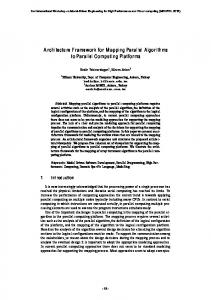
Figure
9.
LB
ATAMM
22
TBIO
performance
_>
plane.
Controller
Dummy of time
Figure
10.
tronsition O
Injection
control
23
implementotion.
procedures,
it
vertically
is
along
line
degrading
throughput
real-time
control
maintaining points from
the
nodes
line TGP
in
operating
example, 7
and
TBO
=
of
observed Figure
2
by
Increasing
AMG
requires
7
TBO
to
horizontally
shown
also
the
preserves
performance.
Such
applications
where points
line
on
a
TBO
to
nodes
resource
=
to
3,
the
can
be
diagram
of
decreases.
requirement
to
in
ATAMM
displayed
shift
the
reduce
resource
while is
maintaining B-H
TBIO
the
4
II.
strategy
line
active
an
at
This TGP
by As
TBO
the
to B-H
active
previous
Operation
in
Figure
of
the
increasing
are
calculated
interval.
of
the
where
implemented
5.
points
in
are
to
reduces
possible
along
strategy
further
for
Operating
from
5.
concurrently
operating
plane is
of
one
control
TBO
useful
number
decreases value
while
are
the
points
By
TBIO
important.
until
Figure
point
applications
by
resources.
number 5
TBO
in
resources
These
performance
shown
is
requirements
injection
the
strategy
very
operating
the
a
decreases
input
increasing
resources.
It
increasing
These
the
is
operating
preserves
processing
resource
interval
required
8 until
Operating
by
minimum
Such
speed
lower
the
strategy
signal
for
time
consider
number
This
B-V
the
This
computing
point.
adjusting
shift
performance.
diagram
any
to
B-V.
and
high
on
possible
degrading useful
for
throughput
for
24
lower
resource
operating
point
requirements. computing
number is
speed crunching
important.
requirements
are
/
6
V It R=2
5
R=4
4
II R=3
1" O 0D
3
R=5 II R=4
p-
2
•
TBO
\
ir
R=7
LB
/
B
R=5
H
1_
0
> 6
J TBIO
Figure
11.
ATAMM Figures
7
8
LB
TBIO
performGnce 5
ond
----)
plone t2.
25
9
for
obtained edge
is
two an
by
adding
an
AMG
place
transitions, edge
is
added
to
input
source
new
graph
has
same
to
not
AMG
the
to
the
imposes
does an
an
edges
which
but
the
imply
so
that
output
increased
a
AMG.
precedence
data the
sink
TBIO
original
A
relation
dependency.
longest is
value
control among
When
such
path
from
directed
increased,
the
but
describes
still
resulting the
algorithm. The
addition
circuits also
of
having
nodes
time. storage
the
node
preserving
on the
and
dummy
and
to
and
value also
balance
edges
and
a
TBO
in be
by the
an
buffer
it
formed
is
to
thus
adding
to
requirements. nodes
that by
is
adding which
computation
provide
additional
Implementation does
not to
require
edges,
graph.
Control
performance
explained
of
point in
more
the thus edges bounds design detail
[3]. To
consider
illustrate again
the
shifting AMG
shown
the in
operating Figure
26
5.
point Adding
horizontally, a
control
a a
increase
Operating is
TBO
zero
control
improve
directed
transition
possible
original
used
dummy
AMG
node.
is
so
avoided
requires
and
new
values
is
graph
node,
can
resource
a
operation
dummy
of
as of
create
problem
operation serves
can
token
node
data
the
per
dummy
circuits
nodes
control
A
memory
Using
count
using
node
a
edge
time
AMG.
output
is
resource.
control
potential
identity
dummy
for
token
the
an The
dummy
This
to
implements
a
increased
increased.
dummy
in
control
edge
directed input
from
node
source
Therefore,
to
edge
read, read
value
of
token
value
of
the
edge
3
edge
purpose
of
diagram
and
The
operating
new
are
on
the
which
are
dummy
node
equal
1
also
peak
diagram
point
Figures
for
plane
by
a
time
per
time
per
node
new 13.
AMG A
TBIO
=
8,
TBO
in
Figure
diagram the
are
shown =
2,
for
the
11.
R
control
as
14.
=
Also
TBIO
SGP
Figure
and
constant
injection
and
The in
to
second
figure
requirement. 2
the the
dummy
this
=
on
a
and
in
the
and
The
The
TBO
points
implemented
added
resource
having
operating
12
7).
3,
has 3.
4.
6,
HOwever,
and
adding
node
4,
from
containing
I
to
by
3,
8.
circuit
increased
to
in
to
nodes
path
(i,
circuit
of
reduced
directed
nodes
directed
are
the
TGP
is
is
is
shown
performance
additional
TBO_
new
directed
This
node
are
reducing the
4.
from
and
new
circuit
CMG
a
contains
graph
a
that
this
control
shown
so
creates
transitions
node
directed
corresponding
new
write
of
token
the
4 which
creates
and
transition
node
sink
for
also
process
to
output
TBIO_
control
3
5
is
shown
=
8
line
described
previously.
for
The
performance
the
selection
algorithms selected point with
by
to value
control
under
ATAMM
R
points
identifying
specific
diagram
and
executing
corresponding a
plane
provides
information
of
time
rules. in
each
resource
of
identifies
R
27
the
the number. the
essential
performance
of
Operating
points
are
performance
plane,
one
The value
point of
associated TBIO
and
TBO
Time
I jTransition Dummy Transition D
2
2
2
Place cp2
/ !
/
I I
Transition
Figure
1 2.
Modified
AMG
28
for
Figure
5.
7
C
o o__ °__
C
E
c4
L_
/
F-
°__
D
L O "4...-
E
c o
_g
_
_O
0
O_
O
AIh ,qp
I1) C_
D "O o c 0 c
E E
>,
E E
a
O
29
0--
b_
Data Packet Number
_
I
3
4
_
1
1
2
±_x I
I
21
6
7
I I
I
I
I t2
I
I
I
I
I
4
I8
Time
_
(o)
l
I
t(4)
5(3)
4(3)(-_,
6(2)
i_
7(1)
I I
t t+TBO
t=OI Time
--_
(b)
Figure
14.
(a)
SOP
for
Figure
I
/F"
I
1 to
I
I
diagram 12
3O
and with
TBO
(b) =
TOP 2.
diagram
)
implemented the
when
number
of
identified. the
resources
with
the
have
Design
PC/AT
compatible
The
this
system
discussed
section, is
Multicomputer
system
described.
IV.1. A
completed
using of
Included
major
a
the
is
modular
a
state
ADM
system
description
redundancy
the
the on
IBM
to
the
system
is
model ADM of
identified
the
ATAMM
and
description.
running of
operate
ATAMM of
diagram
called
ADM
the
are
plane
environment.
components
(AMOS)
bounds
the
under strategy
AMOS Then,
AMOS
are
used
to
(TMR).
Description
VHSIC
Development
the
to
THE
architecture
System
explained
triple
ADM
The
the
performance
windows
of
adjusting
package
is
modifying
performance
constructed
IN
If
point
by
and
software
adaptation
Next,
capabilities
implement
the
realized
and
a Microsoft
resources.
operating
of
TGP
IMPLEMENTATION
Operating is
in
described.
first.
operation
SGP, a
R
nodes,
the
is
new is
calculation
software
AMOS
point dummy
in
with
a
The
computers
IV. In
and
automated
Tool.
then
new
edges
of
been
functioning
the
interval.
ATAMM
ADM
at
construction
diagrams
is
changes,
control
injection
and
system
Operation
graph
input
the
ATAMM Module
prior
to
data
flow
(ADM), the
start
architecture, is of
under the
31
GVSC
called
development implementation.
the and
Advanced will
be
The
ADM
architecture
is
Corporation
and
four
identical
dual
PI-bus.
bus
Also
a
flow
All
Microvax
programs
and
connected Data by
as
a
capable processors
IV.2.
PC/AT
operating ATAMM
used the
back
to
IBM
and
controlling collecting
used
to
1553B
module
addition
in
input
output
IBM and
PC/AT
output,
recovery, and
passing
The
graph
is
link.
the
purposes.
rate
to
module
fault
injection the
1553B
input
algorithm
from
bus
application
real-time,
testing
the
IEEE-488
and to
PI-
memory
communication
injection,
for
for
an
and
the
direct
The
the
graph
over
a
1553B
input
download
line
a
for
of
over
single
PC/AT
the
use
of
over
is
gateway
and
fault
sink
communicate
a
algorithm
consists
Communications
In
for
system
activities.
by
between
of
and
AMOS The
upon
IBM
is
Electric
PI-bus
a
communicate
communications.
source
of
broadcasting
debugging
modification
acts
by
files
is
information
PC/AT.
which
transferred
link
IBM
for
the
as
an
This which
to
serves
also
Westinghouse
15.
processors
computer
synchronous
this
Figure
which
from
the
by
connected
processors
to
are
in
1750A
accomplished
access.
constructed
shown
module
data are
is VHSIC
communication output
being
and to
1553B
thus
the
is
1750A
PI-bus.
Description
ATAMM system rules.
Multicomputer of
the It
ADM consists
Operating hardware of
32
and three
System its
(AMOS)
operation
logical
is is
components,
the based the
Directed Graph
/
Download/Debugging IEEE
488
/
BUS
I
Tool
M IC ROVAX
AMOS
1 750As
1555B
L Comn_unication
/
(4) DUAL
PI
_F,B__c/_ -1
\
t
I BUS
Real-time Data By
Figure
15.
Advanced
Link
Input Output FDT
Transfer Broadcasting
Development
System.
33
Module
(ADM)
graph
manager,
or
resources.
of
the
this
is
from
a
of
the
the
marked
queue
unit
computation,
graph
each
the
to
functional
corresponding operation
to of
requires
a
functional node is
the
unit
the
CMG,
and
is
with
functional memory
graph
global
between units
access functional
this
each
functional
are
transfer units
manager to
graph asynchronous
have
the an
has
to
the
carried
identical
copy
all
three
operation. required
status
write
and
In
The
functional
global
are
also
unit.
the
and
data
unit
code
manager,
PI-bus.
34
update
to
algorithm
executes
The
read
path
algorithm
operation.
memory
over
each
to
graph.
stores
Thus,
unit
unit
communication
graph.
functional
completion
marked
which
the
processors
functional
each
each
functional
the
memory
component
of
perform
for
of
the
communications
a
transitions
the
the
a
1750A At
signals
to
algorithm
the
status
transition
to
computational
(NMG)
that
with
from
output
logical
units
global
marked
read
units
the
assigns
of
requires
path
the
assigned
communicates
the
and
algorithm
graph
assumed
perform
input
functional
system.
sent
The
communication
marked
is
unit.
monitors
a
Each
operating
manager
and
functional
update
graph
of
manager
operation. the
set
when
graph
a message
manager
updates
available
of
a
graph,
the
of
and
manager
algorithm
Therefore,
all
graph
functional
the
It
The
memory,
enabled,
corresponding is
global
computational
graph
unit
the
to unit
of
the
data.
The
memory,
and
out
by
direct
order
to
ensure
that
of
the
graph
data
structure, graph
a functional
data
structure.
transmitted the
to
functional
all
functional
unit
releases
graph
the
functional in
manager
the units
activities
has
functional
units
in
for
processor
failure.
the
need
for
components
of
shown
in
shared AMOS
Figure
labeled
until
its
when
this
unit
an
transition enabled
itself
to
read perform
for
is
the
only
in
at
the
top
the
identified,
the
operation,
35
to
eliminates The
state
units
major
diagram
awake in
the
in
this
this the
queue. a
state
state, CMG
becomes
enabled.
functional
unit the
the
state
resource
of
grabs
the
tolerance
the
In
status
operation
improving
undergoes
state.
monitors
of
number
16.
remains
unit
the
units.
by
of
of
memory
Figure
unit
available
distribution
fault
global
manager
of
time
functional
functional
algorithm
This
of
among
graph
queue
same
then
communication.
the
the
the
only
distributed
functional
all
algorithm
are
of
and
other
represented
Graph
is
for
pictorally
Examine
node
a broadcast,
degree
functional
an
is
time.
at
the
actively
structure
distributed
appears
the
data
increasing
among
AMOS
A
occurs,
functional
a
Initially,
identifier
to
read
17.
graph
top
of
higher
shown
Idle.
transition
on
and
memory
of
the
memory
a given
system a
are
operation
state
at
Also,
by
global
unit
achieving
changing
PI-bus
advantage the
before
However,
active
the
potential
The
the
and
PI-bus
updated
units.
is
the
units
functional
functional
grabs
The
all
The
residing
unit
the
until
a
When assigns
PI-bus,
and
,urce Queue
-
Node
Labels
-
Edge (Data) Connections
Labels
Algorithm Graph
-
Graph
Task/Data
Node
Management
System
Pointers
Tasks
(GMS)
Global Memory Modlf[ed
kernal
Operating
System
(MKOS)
-
Command
Driven
-
I/0
-
Debugger Loader,
File/Block
-
Memory
Resident
Monitor
Drivers Transfers
PI Bus
F'gure
1 6.
Major
components
Operating
System
of
the
(AMOS).
36
ATAMM
Multicomputer
Self
Idle
Z
Node
Examine Graph
Execute Node /F
/R
Figure
tD
17.
AMOS
functiona
unit
3?
state
diagram.
undergoes
another
this
state
from
the
state
transition
transition, top
announcing
of
that
resource
an
algorithm
on
bus.
bus.
functional
algorithm
operation
is
algorithm
operation,
the
initiates
a
broadcast
of
second the
unit
unit
changes
again
PI-bus. the
The
functional unit
transition
is
broadcast
unit queue, and be
and
accompanied
by
a
release queue
by
F,
D,
be of
in or
R
a
of
to
the
commands
from
38
PI-bus
which to
and
all
of other
in a
any
test,
PI-bus, the
of the
state a
third
functional the
state,
functional functional
the
check
This
of
other
releases
state.
bottom
a
functional
self
the
and
includes
the
that
while
memory
the
data
announcing
PI-bus.
global
the
successful
grabbing
PI-
of
a diagnostic
Idle
returned
the
completion
state
initial
"R"
the
the
a
is
the
time
to
initiated
releases
grabs
Test
"F"
until
"D"
corresponds
the
communication
resource updated
to
should
the
this
removed
state
output
Self
After
returns
identifier
At
At
the
state
unit.
functional
bus
memories.
Test
Execute
operation
is
been
unit
unit
During
communication
has
communication
to
bus
the
functional
state
Self
in
complete.
global
a
functional
remains
algorithm
functional
and
state.
identifier
operation the
bus
Execute
unit
queue
Then, unit
the
functional
the
broadcast The
the
the
to
resource the
CMG
unit
can
units.
IV.3.
System The
capabilities
ADM
is
The
graph
Graph is
capable
selected
which
a
It
also
is
period
the
point
to
It ways.
is
However,
ATAMM
model,
context. of
component green
the
The the are (G).
TMR
approach AMG.
The
identified The
structure
of
fault
by in
a
TMR
Triple
the
result
fault
self-test
and
input
of
the
in
state. injection
number
and
faults
can
algorithm
single
in
graph
a
number
or
of
operating changing
to
triplicate
each
of
each
extension, of
an
AMG
different
basis
in
color
of
theoretic
considered
39
the
and
is
triplication
inputs
system by
tolerance
injecting
elements by
the
sink.
implemented
every
a
time.
real-time.
the
is
in
be
unit
from
a
between
operating
units
error
at
The
output
can
which
knowledge
tested
used
time
recover
upon
strategy
the
functional
graph
of
single
The
in
implement
view
a
functional
an
units
to
in
a
features
functional
possible
form.
can
based
be
and
briefly.
graph
Algorithms
three
modify
can
and
method
detects
These
modification of
in
AMOS
real-time
number
error
described
algorithm
source
TMR
by
unit
possible
one
or
voting.
are
periodic,
(TMR)
units.
now
module.
duplex
functional
in
be
1553B
performed by
functional
and
to
Redundancy is
ADM
input
computational
operation
the
single
simplex,
a
Modular
by
the
implementing
assumed
controlled
correct
edge
a
is
in
of
of
has
play
either
is
Capabilities
a
for
purely node
the graph
and
triplicated
each graph
red
(R),
blue
(B)
node
pair
and
the
associated nodes G.
edges
receives After
majority
is
each
all
colored
used
of
Given
a
the
18.
Each
triplicated
acquired, are
nodes
Figure
label
are
data
simultaneously.
in
input
data
accepted
three
shown
a as
and
vote
the
is
node
triplicated of
the
coded
as
colored R,
conducted process
AMG
availability
of
and
and
the
input.
node
three
B
are
The
enabled
functional
units k
to
fire
these
enabled
parallel
and
produces
that
all
nodes,
elements
preserves
the
triplicated
triplicated of
node
the
a
output
triplicated
process
processing
timing
data. node
in
occurs
The
fire
accordance
in
requirement
simultaneously with
the
simplex
model.
V. The of
the
class
focus
ATAMM of
of
which
architecture.
to
the
version In
in
is
to
The
Figure ADM of
be
addition,
also GVSC
19.
system, AMOS,
the
the as
several
on
of
extend
the
and can
in
in features
VHSIC and
the
4O
the
be
four 1750A
features
will
IV, be
VHSIC
processor
instruction consoles
of
this
of will added.
the The
Generic
associated
Section
expand
applied.
the
similarity and
capabilities
thus
spaceborne
structure
new
GVSC
rules
a
architecture
presented
to
implemented
based
Because
THE
System,
ATAMM
(GVSC),
is
is
Operating
which
Computer
breadboard
shown
to
FOR
research
Multicomputer
AMOS
Spaceborne
ENHANCEMENT
present
problems
enhanced
AMOS
the be
set are
hardware present retained. In
this
£
P
(a)
PRR \
AR
BR
P
PG GG BG
AG PGB
P PB, PBB
BB
(b)
Figure
18.
(a)
Simplex
and
representation.
4t
(b)
TMR
AMG node
pair
(/3:
00000
u_ E_ h
Ill
C) c-
Z
O
..0
I
0 (3 co
0
0 co
-I> 0
0 (3 o_
C_ 1.1_
ooo
u_ 42
section, the
the
ATAMM
proposed
model
instantiations ATAMM
is of
model
node
of
and
multiple
distributing
the
and
improvements
to
described. the
failure
of
decomposed
a
are
opportunity
to
improve
throughput
Second, each
having
a
proposed. in
desirable
distinct
the to
source
strategies a
method
for
units
reduce
workload
the
module.
methodologies
for
functional
capabilities
unit
simultaneous
Then,
communication
tolerance new
the
Three
nodes
functional
Concurrent
present
computing before
fault
the
algorithm
is
1553B
to
during
Finally, of
for
is
AMOS
are
recovering
from
complete
AMOS
the
envelope.
Multiple The
the
Proposed
operating
V.1.
the
enhancement many
sink
enhancement of
This
concurrent
in
are
and
First,
multiple
considered.
graphs
described.
because,
graphs,
is
source
This
complexity
an
are
permit
utilization.
node,
implementing
presented.
provides
AMOS
nodes.
desirable
algorithm
sink
to
graph
resource
multiple
and
selected
it
performance
to
generalized
is
decompositions,
play
enhancements
version
associated the
node
Instantiations
can
with be
algorithms
recursion
circuits
throughput
by
allowing
of
the a
initiated where
in
node
the multiple
of
ATAMM
model
another
it
concurrent
43
must time. is
is
Operations requires
operation
throughput AMG,
Node
that
be
all
completed
However,
in
limited
by
not
possible instantiations
to
improve of
node
operations.
Therefore,
enhanced
to
nodes.
A
include
The
the
the
NMG
that to up
of
the
as
as
can
n It
present
is can
bounded.
tokens
to
CMG this
ensure
belonging
order.
To be
rule
to
for
to
the
no
tokens
and
the
model
as
data
essential an node
input will
44
node
the
number
the
m. like
the
but
the are
management
deadlock
modified
vacant
However,
graph
free
are
packet
node
firing,
model,
properties,
be
provide
a
(1-bounded),
packets
in
indicate
OE
from
consistent.
data
PR
requires
ATAMM
m
tokens
edge
the
and
concurrently
data
to
is
an
of
edge
edge
on
model
safe
and
modification
assigned
additional
different
read
n
large
AMG
concurrent
initial on
be
modified
longer
reason,
indicate
tokens
the
ATAMM
labeled
as
output
as
reachable
are
OE
prerequisite
least
that
these
each
a
by
can
which Since
at
that
guarantee
tagged
in
be
live,
and
to
m
as
shown is
For
required
firing
be
NMG
The
The
be
of
multiple
the
20.
deposited.
chosen
on
placed
operation.
container
include
are
locations
model,
enhanced
will
node
of
accomplished
units
model
section.
edge,
Figure
ATAMM
instantiations
this
to
is
functional
be
data
number
m
memory
operation output
as
the
n
in
in
n tokens
labeled
shown
perform to
PR
many
nodes
the
generalization
ATAMM
tokens,
that
concurrent
presented of
AMG
Multiple on
proposed
this
are
generalization
NMG.
tokens
for
example
instantiations
is
multiple
strategy
illustrative
it
not
all
is
and
that
mixed
graph
that
in
tokens
identity. so
n-
The a
read
(n)
0E
A
iFt_., _
" OF
NMG
Figure
20.
EDGE
LABELS
IF
Input
Buffer
IE DR
Input Data
Buffer Read
PC
Process
Complete
PR
Process
Ready
OE
Output
Buffer
Empty
OF
Output
Buffer
Full
The NMG model.
for
Full Empty
the
enhonced
45
ATAMM
node
is
enabled
having
the
only
tag
graph
for
the
for
managing
In
is same
should
not
this deadlock
node
operation
the
incoming for
way,
made
add
each
identifier
instantiation. The
when
of
complete
significantly
sequencing
to
the
token
any are
being
assured. processes
order.
overhead
node
is
concurrent
in
tokens
a
appropriate
allowing
graph
contains
next
data
by
to
tagging
the
proper
free
edge
Procedures developed
of
the
and
operating
system. An this
example
is
enhancement
Figure
21.
to
If
initiated
a
by
node
the
each
of
AMG
general,
nodes
multiply
instantiated
output
data
Therefore, the
only The
Figure node
to
occur
enhanced
SGP
and
diagram
achieve
number a
TBO
then
of
node
model,
factor TGP
in
for
diagram
concurrent
value
of
46
2
is
a
of
node
AMG
to
2
the 4
and can
calculation recursion
recursion
determined
can
be
presence 5.
In
not
be on
circuit.
circuits
throughput TBO
5
depends
are
performance. =
2 are
instantiations is
limited
circuits
for
in
being
of
from
the
shown
concurrent
TBO
nodes
of
before
three
results
each
ATAMM
the
graph
recursion
previous
limiting
The
in
the
if
consisting
significance
complete
this
allowed,
because
the
for
limitation
circuit
the
must
However,
are
theoretical
22. 2
2
which
from in
2.
throughput
recursion
TBO
the
Consider
operation
then
node
demonstrate
model.
node
time,
of
to
ATAMM
labeled
This
the
the AMG
second
instantiations achieved.
presented
shown
required by
counting
in of the
0
E
U C 0 _cC
_C
0
0
El.
E O x
C',4 l
°--
1,
47
I
I
I
t2 1
1 I I 1
5
Data
)(
1 1 I
4
/
1 I I 1 I I
2
i
packets
(a)
Single
Graph
P)ay
1 (5)
k I
2 (4)
K
(4i
I
I (4)
2
2 (2)
I _2)
I I
3 )
1 1 t
Time
lt+TBO
t=O
I
J_
TBO
=
2-
('b) Total
F'gure
22.
Graph
(a)
SOP
diagram
for
TBO
=
2 for
48
Play
(b) the
TOP AM0
diagram of
Figure
21.
number
of
data
times
packet
required this
4
at
the
are
by
I,
A
three
ultiization
better
2
shown
NASA
Langley
GVSC
system.
Multiple In
addressed
the
order in
to the
ATAMM
a
Center
containers
calculated
in
is
the
nodes
4
and design Old
and the
resource
tool
3.
initial
resource ATAMM
significantly
the
case
obtain
can
be
is
being
Dominion
and
utilization
is to
TBIO,
edge
enhanced
problems,
As
data
on
of
and
23.
and
many
2
processing
performance model
nodes
number
Figure
procedure
and
3
from
relations
required
model.
design
Such
tool.
is
correct
and
TBO
different
data
connecting
the
In
both
with
because
node
edge
shown
24.
enhanced
Graph
also
example,
ATAMM
Figure
Research
node
throughput
present
including
output
are
place as
diagram
of
while
the
to
CMG,
model,
design
this 4
and
TGP
predecessor-successor
performance
the
ATAMM
software
3
of
in
with
performance,
the
containers
used
the
the
graph
In
and
throughput
initial
each
packet
enhanced
for
possible
number
data
is
the
is
The of
data
comparison
model
in
operations.
nodes
in
appears
monitoring
information
tokens
V.2.
output
node
connecting This
the
processing
packet
2
numbers.
diagram
among
node
are
with
the
predictable
automated
in
developed
University
a by
for
the
can
be
Strategies expand
ATAMM
the
class
context,
it
49
of is
problems desirable
which to
enhance
the
C_ EL_ © (_9 < _C
©
C O _C CLJ
¶ °-
LJ_
50
Theoretical Resource
-S
Limit
..c
O
Enhanced ATAMM Limit
..c
f
Largest Recursion Time ATAMM Largest Node
Limit
t_ or
Recursion Time R
_ max
new
R rna_
(with
Resources
enhanced ATAM M)
Figure
24.
Ideal ATAMM
throughput
improvement
model.
51_
using
the
enhanced
ATAMM
model
purpose
so
of
this
implementing
are
parallel
arise
separate
in
are
analytical
procedures
G,,
G
each
having 25.
and
played
that It
these is
various
operating
in
done
now
collection own
input
graph
assumed
In
to
as
which
are
commonly
the
proposed
graph-theoretic
for
single
of
algorithm
and
strategies
important,
time
the
strategy,
problems
that
Gk
source
has
a
in times
that
based
performance
can
be
graphs.
the
parallel
is
determined
of
the
same
execution in
for
52
sink,
can
each
shown
time
TBIO(k)
is
order
of
magnitude.
not
all graph
G k.
assumed
between be
The
, in
it
single graph
---
where
strategy, the
G2,
as
relationship
and
as
Gx,
computation
TBO(k),
phase
the
graphs
output
unique
are
unpredictable
Just
and
period
is
parallel. point
insure predicting
repetitively
graphs
controlled. played
a
performance
also
for is
its
Each
to
Equally
multiple
referred
different of
ATAMM
Strategy
denote
Figure is
as
Execution
Let
classes
for
under
implementing
multiplexing
The
The
strategies
graphs
are
time
strategy.
selected
just
Parallel
the
implemented.
multiple for
applications.
strategies
formulated,
of
be
several
strategies
different
real-time
propose
play
strategy,
address
can
strategies
interrupt
to
to
These
execution
selected
is
presented.
priority
graphs
simultaneous
Three
graphs
multiple
section
the
rules.
the
that
the
accurately graphs
are
case, operating
an
C:
O O
Figure
25.
A collection
of
olgorithm
53
grophs
(G).
point
is
characterized
TBO(k),
and
produce
this
the
phase
the
desired
for
each
strategy
The
parallel
necessary
to
high
data
efficient
use
selected
to
When select It
play
of
several
according
to
strategy
is
utilization
peak
will
possible
when
one
data
graph
more
useful
possible to
graphs
requirements.
54
Such
needed parallel
where
it
is
achieving
a
problems
often
applications. point
the
decreased
completely
lead
at
the
while
operating
resources,
A
play
resources of
of
For must
be
requirements.
with
ranking.
or
is
reduction
limited
number
graphs
display
to
concerning
total
the
graph.
resource
can
necessary
all
and
26.
each
suspend
it
R(k)
simultaneously
operate
to
a priority
Figure
TBIO(k)
the
of
pictoral
each
with
graphs
that
and
resources, high
sum
times
knowledge
that
strategy
for
no
graphs,
the
graphs
rate
operating
is
in
execution
processing
avoid
which
also
shown
is
insure
is A
resources
there
to
graph. is
of
the
point
repetition
in
of
required
individual
performance
Since
operating
execution
the
number
performance.
resources
the
occur
minimum
relationships
available
very
by
user
time the
levels
have
large
able
performance.
play
disadvantage
low
is
of
graphs of
this
of
resource
peak
resource
q, ol
G 5 (1)
(D
(35 (2) G 2 (2)
0 09 q)
[E
I
6; 1 (2)
> Time
Figure
26.
Parallel for
execution
multiple
graphs.
55
strategy
Time
Multiplexing Again
G2,
...,
It
is
let G,,
is
assumed known system
is
requirement summation
at
of
resources.
in
Figure The play
each
time
time
each
The
input
the
pieces
total
more
than
no
multiplex
is
graphs
is
time
for
graph of the
is
a puzzle
shown
is
when
a each
resource and
available
strategy
An
specifying
injection
like
also
graphs.
thus
individual
TBO
strategy,
various
graph,
time
It
different
the
sink.
time
multiplexing
together
time
repetition
the
fit
occur
in
strategy
graphs to
to
multiple
parallel
to
output
times.
that
multiplexing
several
important
results
computation
G,,
in
number
pictorially
27.
relative
often
unique
so
instant
The
and
between
for
graphs
source
common
the
shared
envelope.
envelopes
a
inputs
selected
selected
a
marked
computation
In
time
is
has
all
controlled.
requirement
graph
to
algorithm
input
share
between
are
point
resource
of
be
own
graphs
time
of
graph
compared
resources
operating
its
each
all
the
can
collection
having
that
that
a
that
large
and
be
each
but
which
long
G
assumed
TBIO(k),
to
Strategy
the
with
short
real-time
sensors high
execution
common
computation
achieve in
a
time
utilization strategy,
repetition of
computation
control
and
useful
of
system
the
56
user
graph,
times.
This
able
necessary which and
Such
strategy
it
is
the
use
naturally As
to
is
problems
requiring
resources. is
is
period
each
applications
actuators.
it
with
specify
the which
/_
Total
? Co (D (D
o (/3 ©
Individual
FY
G2-_
> T Ti me
Figure
27.
Time for
multiplexing multiple
57
graphs.
_-)
strategy
graphs
will
resources
Let defined
Strategy
G
a
denote
time
collection two
assumed
that
priority
are
for
to
new table.
the
number
of
to
graph
allowed data
to
system
to
and
useful
performance
play
as
in
designed
the to
resources.
operating This
in
is
is
only
a
graph
due
second one to
strategy,
is
graph
collection
again
Therefore,
emergencies
or
G
status
resources
resumes.
is
highest
available"
system
the
When
allocated
and
of
it
occasionally.
"resource
G
a to
inactive
ATAMM
strategy
denote
interrupt
addressing
this
unexpected
tasks. all
Whenever
table
which
exhausted,
three ADM
continuously
will
according
in
of
present
point
play
resources,
H are
for
to
H
an
execution H
H occur
play
on
Let
Collection
system
playing
parallel
priority
graph to
G,
but
In
computational
controlled
system
data
input
is
Time
data.
or
high-priority
be
the
graphs
the
defined
strategies,
access
allocated
strategy
also
available,
When
to
n
strategy.
graphs,
input
terminated
will
m
input
become
only.
as
of
according
execution of
is
collection
multiplexing
of
absence
data
performance
Interrupt
architecture
the
the
in
decreases.
Priority
or
degrade
system.
number
obtained
constructed
the of
of
resources an by
will
operating
number
from
off-line
58
strategies The
monitor
the be
operation
system available
changes,
operating the
be
user
a
point with
the
support
of
point
design
is
achieved
(setting
control
injection
rates
shown
in
source
edges for
the
and
the
of
be
over
distributed
to
number
reduce
1553B
the
between
the
also
1750A
will
single
stamp
transmission
to
PC/AT.
implementing
the
source
is
node
this
the
ATAMM
single
graph
the
In
the
sink
nodes
to
the
This 1553B In
the
performance
via
the
PI-bus.
nodes
section, in
the
a
the sink is
the GVSC
nodes
done
to
Module,
and
GVSC,
the
information
information
next
in
in and
units.
and
PC/AT
realized that
component.
data
the
are
source
performance
and
the
process,
into
proposed
assigned
and
graphs
adjusting
control
ATAMM,
functional
pass
time the
of
of
units
of
multiple
activities
will
operating of
by
integrated
sink
It
set
new
(AMOS).
graph
the
the
simply
be
and
feedback
implementation
complexity
module
to
System
ATAMM,
of
The
A
collection
nodes),
graph. is
tools.
the
dummy
Module.
implementation
the
each
ADM
Communication
limit
and
28,
present
software
reconfiguring
Operating
node
1553B
simulation
by
Figure
Multicomputer In
and
The
1553B
prior
to
procedure
for
functional
units
is
described.
V.3.
Distributed Each
of
distinct
source
a
node
source
Sources
the
Sinks
concurrently
node are
and
to
and
processed
a distinct
supply
new
input
59
sink data
multiple node. at
The
graphs
has
activities
specified
intervals
a of
AMOS
MULTICOMPUTER ARCHITECTURE
Graph
Number
Characterization &: Injection
Rates
(Control
Signal
of
Resources (Feedback
Operating
Point
Signal)
Table
AMOS
On-Line
Off-Line
Performance
Design/Simulation Tools
Figure
28.
Control
strategy
6O
Operation
for
GVSC.
Design
of
time
and
to
presence
of
new
collect the
amount
graph
the
unit
over
Graph
and
diagram
29.
are As
strategy
shown
in
state,
is
firable
there
no
highest
priority
repeats
the
found,
the
is
search
it
unit
source, firable for
functional
a
a
node,
acting
the
by
a
done
for
each
for
functional
also
checks
for
activities
firable
source.
charts
the
there
the
the
are
and
shown
graph
is If PI-bus
Execute
in
Figure
no
enters
first.
searches
a
state
manager
sources unit
Examine
unit
Examine
firable
If
61
be
graph
functional
functional
grabs
is
functional
the
modifying
flow
node.
unit
data
the it
should
sink
be
units.
as
for
can
module,
it
to
update
reduce
The
modified of
to
to
input
and
AMOS
The
searches
and
the are
output
Whenever
source
help
and
examines
nodes.
the
the
node
sinks
that
implemented
16.
with
and
functional
Figure
code
queue
the
sink
processors.
of
of
functional
Examine
1750A
states
described
the
sources proposed
indicate
new
of
firable
of
a
communication
way,
set
Execute
as
states
the
new
the
that
the
is
to
PC/AT,
of
processing this
the
a
1553B
the
as
of
the
resource
well
In
to
indicate
It all
structure
activities
simplify
the
the
sinks.
distributed
of as
completes
This
to
to
to
data
transmission
required
top
sources
firable
The
processors.
the
firable unit
order
broadcast
at
data.
implementation
1750A be
graph
for
activity
that
the
structure
In
of
the
data
data
generated.
in
input
output
graph
felt
update
such firable and
If
for
the
node,
it
node
is
enters
the
Examine Graph
> Y
PI bus
N
X
I F[ re//'
I
__j_[ab Pl bus Local
lF
\
,"
Update
N(
Source[
Y /
Execute
\/
Transfer output
I F,
y
I
t-...
Fire Source
(if
any)XX,
Process to
Sink
N
Grab
PI
bus
/ /
, J
PI
Figure
29.
Modified
bus
Examine
"D
_
/
Broadcast
Data
Broadcast
output//
(if
and
62
any__
Execute
/
/
states
for
GVSC.
Execute
state.
grabs
the
a
a firable
PI-bus,
indicate If
If
firing
of
firable
Execute
updates the
node
broadcasting released,
and
Examine
is
firable be
"D"
command.
found,
the
functional The
to at
the
the
data
of
that
a
to
each
is
new
a
is
to
output
PI-bus of
provide
If
as the
be
deposited
is the
for a
part
update
by
sink
search
process.
can
the
issued
unit
broadcast to
node.
beginning
state
to
enters
the
the
node
used
firable
is
structure,
unit
structure
unit
functional
also
also
for
command
Execute
completion
functional
data
looks
returns
the
broadcast
graph
"F"
the
output
the
the
functional
an
in
found,
then
that
sink
indicate
of
unit
change
is
the
graph
require
The to
and
updated
fired,
structure
source,
the
sinks
can
copy
Otherwise,
state.
activity
its
is
state.
source
of
graph
sink the data
in
the
types
of
node
and
sink.
V.4.
Fault The
faults, a
Tolerant
ADM a
fault
first
fault
second
the
resource
from
AMOS the
is
is
is
during
occurs
during
the
and
purges
death
of
occurs
detected
to
capable
which
detected
The
of
system
which is
Strategies
be
its in
itself enhanced
of
a
the
so
the
that
functional
the
two
State
each
a
resource. the
of The
system in
of
a
by
system.
unit
63
of
discarded
Diagnostic
from
with
processing
self-test
effects the
dealing
is of
a
use
The of
TMR.
resource
and
present
version
able
recover
the
to
four
AMOS
states.
The
detect a
and
recover
resource
in
any
of
the or
broadcast. possession
whether state
after
divided assessment, in
to
propose
this
type
system
fault.
of
is
assumed
that
fault.
and the
be
The
and
generate
does
view
not it
of
back
explanation
of
fault PI-bus
fail
while
not
clear
the
the
grabbed
technique
detection, to
of
is
damage
service,
each
of
a
is in
fault
system
death
internal
since
to
instructions
maintained
overall
strategy The
to
not
bus,
phases:
recovery brief
due
does
or
a
executing
resource
released
following
A
(e.g.,
communication
the
30.
stops
AMOS
failure)
will
the
of
resource
power
the
system
Figure
is
states
bus
into
section
the
of
the
this
when
total It
of from
occurs
detection
in
purpose
as
shown
these
phases
follows.
Fault
Detection One
of
context
is
TBO
which
at
real-time shortest
the
to
to the
graph detect
detect the
period
a
of
fault
consequences
is
By
of
the
a
fault
time
avoid
using
fault.
to
can
the
system A
64
detection than
Due
any
detection
the
less
operating.
important
to
fault
before
in
is
time
execution.
effective
fault
it
This
a
of
system
systems,
performance. the
goals
to
detect
be
a
status,
strategy
is
by it
the
nature
of
in
the
of
system
monitoring is
completely being
this to
fault loss
achieved
stopped
equal
the
significant
graph has
or
in
possible due
developed
to to
NO
FAULT
Fault Detection
FAU LT
System back to Service
Figure
Damage Assessment
30.
AMOS for
fault
0VSC.
65
management
process
use
the
graph
Damage
status
a
fault
is
confined.
The
detection
scheme.
specific have
failed
graph,
to
can the
resource
by
resources.
System
Recovery After
the
of
all
been
have
to
resource. state
detection
of
generated
be
prior
inquiries
by
to
graph the
been and
the
fault
may fault.
a
from
the
is
any
type
this
The
to
The
the
assumed of
be
may
an
from
information
returned recovery
must
be
that
may
queue
resource
to
the
phase
other
possibly
system
purging
a
ultimately
the
invalid
the _
render
is to
by
the
resources
inquiry
the
status
state
be
of
will
condition
g.,
fault
possibly
status
and
available
system
66
the
time-outs
(e.
and
should
that
of
that
graph
valid
have
assessed
Therefore,
confined,
node). to
resources
and
data
process
restored The
fault
has
be
strategy
queue,
to
damage
derived
observation
unresponsive
unwanted
unfinished
by
of
must
circumstances.
resource
direct
faulty
is
the
given
type
hence,
confirmed
purged
the
available
totally
damage
detection
isolate
achieved
The
resources;
fault
help
be
system
assessment The
under
themselves.
an
detection.
detected,
damage
enough
assessment
or
fault
Assessment Once
have
for
update
queue the last is
may
faulty valid used
to
perform
the
appropriate
System
Return Having
bring
the
firing
recovered
node
the
phase,
continue
with
All
of
out
by
are
working
placed
a
in
recovery
fault
performance
that
these
left
the
the
system
system,
This
to
a valid
to is
a
the
next
normally
would
by
faulty
unfinished
returned system
status.
valid
considered
a state
in
repaired
step be
is
to
done
by
resource. the
and
system
ready
to
operation.
the of
algorithm This
fault
the
that
the
67
The
a resource system
graph
and
can
very
be
it
carried
resources
system is
may
while insures
be
healthy
graph.
feature
tolerant
phases
remaining
instead,
means an
the of
recovery;
on
recovery
while
system. highly
and
remainder
This
working
is
service.
resource
state
the
to
detection
state.
in
repaired
is
normal
on a
or
was
the
single
concurrently a
back
system
recovery
of
Service
system
a
After
To
rollback
placed
reliable.
the
not in
capable
recovers
that
is
a of
from system
REFERENCES
[1]
J.L.
Peterson,
Systems, [2]
Roland
Englewood R.
Mielke,
"Modeling Processing," 683,
[31
August
Cliffs, John
NJ,
W.
T.
University,
J.W. in at
Prentice
Modelinq
Hall, and
of
1981.
Sukhamoy
Som,
Performance for Concurrent Report 4167, Grant NAG1-
Norfolk,
and Enhancement for Ph.D. Dissertation, VA,
May
1989.
"ATAMM Multicomputer System Design," Old Dominion University,, Norfolk, VA,
Stoughton, and R.R. Mielke, "Performance the ATAMM Data Flow Architecture," the Ninth IEEE International Phoenix
on
Computers
March
Murata,
21-23,
and
Communications,
Scottsdale,
1990.
"Modeling
Systems," Handbook C. Ramamoorthy Reinhold,
the
1988.
S. Som, Modeling Presented Arizona,
and
Stoughton
Optimum Time NASA Contractor
W.R. Tymchyshyn, Master's Thesis,
Conference
[6]
Theory
1988.
Dominion
August
[5]
and
Net
Sukhamoy Som, "Performance Modeling the ATAMM Data Flow Architecture," Old
[4]
Petri
and
Analysis
of Software Enqineerinq, Editors, pp. 39-63,
1984.
68
of
Concurrent C.
Van
vick and Nostrand
Report %.3r0"_ 5*",_e
t_3t'.3ulC< ",Om,'_ 51'8hC_
1. Report
Documentation
Page
3"%3
2. Government
No.
Accession
No
3. Recipient's
Catalog
No.
NASA CR-4339 4. Title
and Subtitle
5, Report
Algorithm to Architecture Mapping Model (ATAMM) Multicomputer Operating System Functional Specification
November
7. Author(s)
R. Mielke, J. Stoughton, and B. Mandala
S. Som, R. Obando,
Date 1990
6. Performing
Organization
Code
8. Performing
Organization
Report
No,
M. Malekpour 10. Work
Unit
No.
590-32-31-01 9. Performing Old
Organization
Dominion
P.O.
Box
NameandAddress
University
Research
11. Contract
Foundation
6369
Norfolk,
23508-0369 13. Ty_
Agency
Name
and Address
Langley
of Report
and Period
Contractor
National Aeronautics & Space Administration Langley Research Center Hampton, Virginia 23665-5225 15. Supplementaw
No.
NCCI-136
Virginia
12. Sponsoring
or Grant
14. Sponsoring
Agency
Covered
Report Code
Notes
Technical
Monitor:
Interim Report February 1990 - August
Paul J. Hayes
1990
16. Abstract
A functional description of the ATAMM Multicomputer Operating System is presented. ATAMM, an acronym for Algorithm To Architecture Mapping Model, is a marked graph model which describes the implementation of large-grained, decomposed algorithms on data flow architectures. AMOS, the ATAMM Multicomputer Operating System, is an operating system which implements the ATAMM rules. A first generatic version of AMOS which has been developed for the Advanced Development Module (ADM) is described. A second generation version of AMOS being developed for the Generic VHSIC Spaceborne Computer (GVSC) is also presented.
17. Key Words
(Suggested
Concurrent 19. SecuriW
Cla_if.
18. Distribution
by Author(s))
Data flow computers Multicomputer operating Petri nets
system
FORM
Subject
- UNLIMITED
Category
33
Processing (of this
report)
20. SecuriW
Unclassified NASA
Statement
UNCLASSIFIED
Cla_if.
22. Price
(of this page)
A05
Unclassified
1626 OCT 86 For sale
by the National
Technical
Information
Service,
Springfield,
Virginia
22161-2171 NASA-Lax_ley,Ig"


![Mapping a Domain Model and Architecture to a Generic Design [PDF]](https://m.moam.info/img/260x300/mapping-a-domain-model-and-architecture-to-a-gener_64a3372d098a9e0e678b4660.jpg)