sensors, the dither effect is eliminated at the gyro zero angular rate with respect to inertial frame rather than at its zero attitude with respect to the platform [2].
ISSN 2075�1087, Gyroscopy and Navigation, 2012, Vol. 3, No. 2, pp. 120–123. © Pleiades Publishing, Ltd., 2012. Original Russian Text © B.V. Klimkovich, 2011, published in Giroskopiya i Navigatsiya, 2011, No. 4, pp. 57–62.
Algorithmic Compensation of Attitude Error in a Dithered Ring Laser Gyro B. V. Klimkovich Kamerton Design Bureau, Minsk, Belarus Received May 10, 2011
Abstract—The paper focuses on algorithmic compensation of attitude error in a dithered RLG without an attitude sensor. This approach is shown to offer angular accuracy as good as provided by an attitude sensor. DOI: 10.1134/S207510871202006X
INTRODUCTION Ring laser gyros are extensively used in strapdown inertial navigation systems. However, there is a great problem associated with RLG application, which lies in lock�in of counter�propagating modes and in the use of mechanical dither to suppress this effect. If the lock�in problem is fixed using dithering, additional oscillatory rotation should be subtracted from the gyro output to determine the attitude of the platform bound with the strapdown inertial navigation unit. It is done using an attitude sensor or an angular rate sensor. The former determines at what time instants the beat frequency between the counter�prop� agating modes reverses its sign. Difference between the numbers of interference oscillations (cycles of the beat frequency) per half dither cycle determines the varia� tion in attitude [1]. An alternative method of dither effect compensa� tion is to apply a double photosensor, where the first photodetector is shifted with respect to the second for a quarter of interference pattern. The signals from two photodetectors, after amplification and digitization in the comparators, are fed to the trigger and generate the signal of reversing the direction of RLG rotation with respect to inertial frame. Unlike the use of attitude sensors, the dither effect is eliminated at the gyro zero angular rate with respect to inertial frame rather than at its zero attitude with respect to the platform [2]. This method, however, suffers from a significant drawback, namely, an additional attitude error caused by the varying dither amplitude (due to noise intro� duction to suppress the lock�in effect) and by the vary� ing platform angular rate [3]. Commonly, a forward� backward counter is used to count interference oscil� lations per half dither cycles, which, in its turn, brings an additional attitude error. This effect is most con� spicuous during the conical motion of a strapdown measurement unit. This study is devoted to algorithmic real�time com� pensation of additional attitude error associated with
the varying dither amplitude and varying input rate. Interference oscillations should be counted per half dither cycles using a high�speed digital signal proces� sor (DSP), with simultaneous compensation of the above�mentioned error. Application of DSP in RLG data processing and control units allows the dither frequency to be pro� grammatically tuned to and kept in mechanical reso� nance, and provides stabilization and noise introduc� tion to dither amplitude. The DSP is also used to search the optical mode of laser radiation, to maintain the perimeter of ring laser so that radiation is maxi� mum, and to amplify the photosensor signal. Thus, on the one hand, DSP application greatly simplifies the electronics of RLG processor, and on the other hand, enables the use of advanced methods to introduce noise to dither amplitude [2] and to cor� rect the RLG output. ALGORITHMIC COMPENSATION OF RLG ATTITUDE ERROR To analyze the proposed method, we consider the basic RLG equation [4–6]: ∂ Ψ = 2πM (Ω (t) + Ω (t)sin(ω t ) 0 d d (1) ∂t + Ω1 sin(Ψ) + Ω 2 cos(Ψ)), where ψ is the phase difference between RLG counter�propagating modes; M is the gyro scale factor (~105); Ω0(t) is the input rate; Ωd(t) is the peak dither rate, ωd is the dither circular frequency, Ω1, Ω2 are the real and imaginary parts of complex lock�in threshold (algorithmic compensation of random walk caused by zero crossing and associated with two last terms of (1), is not addressed here. Hereinafter, Ω1 = Ω2 = 0). We integrate the left�hand and right�parts of (1) over time for times t at even zero crossing (as counted since the start of signal processing), considering that
120
F (t ) =
t
∫ Ω (τ)d τ is the desired attitude of the plat� 0
0
ALGORITHMIC COMPENSATION OF ATTITUDE ERROR t ∂ Ψ(τ)d τ is the number of interfer� form, N (t ) = 1 0 2π ∂τ ence oscillations at time t with account for the sign change. The integral of the second summand in (1) can be represented in the form:
∫
t
∫ Ω (τ) sin(ω τ)d τ p
d
0
2πn
=
∫
A(ϕ) sin(ϕ)d ϕ − Error ≡ I − Error,
0
where A(ϕ) = Ωd/ωd, and the Error summand is caused by mismatch of time instants 2πn/ωd ( n = 0, 1, 2, …) with times of even zero crossings with Ω 0(t) ≠ 0. We take integral I by parts: ∞
I =
2j (−1) j +1 ∂ 2 j A(ϕ) ∂ϕ j =0
∑
2π n 0
(2) 2 2 ∂ ∂ = − A(2πn) + A(0) + 2 A(2πn) − 2 A(0) + ... ∂ϕ ∂ϕ For further discussions, the behavior of functions Ω0(t) and A(ϕ) should be considered. The function Ω0(t) determines the rate of change of the platform attitude. The vibration component in the platform motion does not affect its attitude, so the function Ω0(t) can be considered slowly varying during the dither cycle (with dither frequency 350–400 Hz). The function A(ϕ) varies due to introduction of additional noise to dither amplitude for reducing the lock�in. The dither mechanical oscillatory system has a Q�factor of about 100, so relative variation of A(ϕ) during a 2π oscillation period is max 1/Q ~ 10–2. Therefore, the second and all subsequent even deriva� tives in (2) are at least four orders of magnitude less than the first two summands and can be neglected. Therefore, the following can be written: N (t) Ωd (t) − Ωd (0) (3) F (t) = + + Error; M ωd To determine the platform attitude without using attitude sensors, the variations in dither amplitude and additional correction for nonzero angular rate Ω0(t) should be taken into account. The data accessible for analysis and processing in DSP are the numbers of interference oscillations between successive zero crossings. Using (3) in prac� tice requires that a formula for estimating peak dither rate Ωd(t) and platform angular rate Ω0(t) from two successive numbers of beats N1 and N2 be obtained. Integrating (1) between t0–t1 and t1–t2, where t0, t1, t2 are successive instants of time when the left�hand part of (1) turns to zero, gives: GYROSCOPY AND NAVIGATION
Vol. 3
No. 2
121
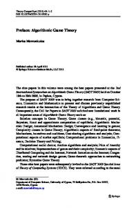
Ωd (cos(ωd t 0 ) − cos(ωd t1)); (4) ωd Ω N 2 M = Ω 0(t 2 − t1) + d (cos(ωd t1) − cos(ωd t 2 )). (5) ωd Zero angular rate with t0, t1, t2 provides the follow� ing equations: Ω 0 = −Ω d sin(ωd t 0 ); Ω 0 = −Ω d sin(ωd t1); (6) Ω 0 = −Ω d sin(ωd t 2 ). Combining and subtracting (4), (5) with account for (6) yields (N + N 2 ) (7) Ω 0 = ωd 1 ; 2πM (N 1 − N 2 ) (8) Ω d = ωd , 4M ( 1 − x 2 + x arcsin(x)) Ω where x = 0 < 1. Ωd It should be mentioned that N1 and N2 have oppo� site signs, so we denote dN = N 1 − N 2 ; N = N 1 + N 2 , where dN is the difference between the numbers of interference oscillations over half dither cycles, N is the total number of interference oscillations during the dither cycle. Considering the smallness of term x and expanding (8) in a series (containing only even degrees of x) yields the estimates of two last summands in (3), which describe the correction of platform attitude with account for the varying dither amplitude and varying input rate: N − N0 F (t ) = 1 N (t ) + − β(N 0 )X 2 , (9) M 4 where N0 is the average number of interference oscil� lations during the dither cycle (a constant reference value used by DSP to automatically maintain the dither amplitude); X = dN , β(N 0 ) is the proportional� N ity factor depending on the average number of inter� ference oscillations N0. The algorithm of dither effect compensation was numerically modeled to test its performance and to determine the dependence β(N 0 ). The calculations were performed for the dither resonance frequency of 370 Hz and Q = 95. The dither average amplitude was varying from 2 to 6 arc min. To introduce noise to dither amplitude, a pseudorandom component was introduced to the dither drive signal. The RLG scale factor was M = 105. The platform moved as follows during the simula� tion: before the first second, no rotation (Ω0(t) = 0 ), after the first second, oscillatory rotation with 1 Hz frequency. A particular case of noise introduction to dither amplitude is presented in Fig. 1. The vertical axis is the
2012
N 1 M = Ω 0(t1 − t 0 ) +
(
)
122
KLIMKOVICH Error, rad × 105 5 1 4 3 2 1 0 2 –1 –2 1
0
2 t, s
Fig. 1. Time dependence of attitude error during the platform model motion.
β 71 66 61 56 51 46 41 36 31 26 250
300
350
400
450
500
550
600
650
700 N0
Fig. 2. Dependence β(N0).
difference between the exact and calculated using (9) attitude values in rad multiplied by 105. In Fig. 1, line 1 does not consider the corrections (two last summands in (9)), and line 2 considers the corrections. Standard deviation of the difference between the exact and calculated attitudes with account for the corrections was 0.15 × 10⁻⁵ rad, and without account for the corrections, 1.8 × 10⁻⁵ rad. The corrections reduce the attitude error by an order of magnitude and
make it far less than the one observed using the attitude sensor (RMS error of the attitude sensor is one count of interference pattern or 1 × 10⁻⁵ rad). The dependence β(N 0 ) was calculated for different dither amplitudes with minimum standard deviation of the above�mentioned difference (Fig. 2). Regression processing of simulation results gives the following equation: β(N 0 ) = 0.097254N 0 + 2.7571.
GYROSCOPY AND NAVIGATION
Vol. 3
No. 2
2012
ALGORITHMIC COMPENSATION OF ATTITUDE ERROR
123
It is important to note that during X calculation, the current value of dN − difference between the num� bers of interference oscillations per half dither cycles – contains a significant noise component not associated with actual motion of the platform, which is rather slow. Therefore, Ω0(t) should be characterized not by dN, but by its averaged value dN f , which was accounted for during the simulation. To this end, the current value of dN for the last dither cycle was pro� grammatically low�passed. The filter cut�off fre� quency should match the maximum maneuverability of the vehicle for which the INS is designed. Here, a second�order low�pass filter was applied [7]: dN f = K 1dN + K 2dN f −1 + K 3dN f −2,
ence. The parameter under test was azimuth error after a one�hour motion of the vehicle. The experimental azimuth error was found to be 0.039 ± 0.03 °/h.
where dN f is the current filtered difference; dNf – 1, dNf – 2 are the filtered differences for previous dither cycles; K1, K2, K3 are the filter gain factors. Figure (1) also suggests that the attitudes found using this algorithm exhibit some systematic bias. Its sign depends on the sign of the first half dither cycle. The bias does not contribute to the error of strapdown INS, since only the difference between attitudes is physically significant.
REFERENCES
CONCLUSIONS The simulation results and full�scale tests of strap� down INS suggest that algorithmic correction of dither effect provide the attitude as accurate as the one produced by an attitude sensor. This method, however, excludes the use of an additional hardware compo� nent, which makes the inertial navigation unit more robust, and is in line with the universal shift from ana� log to digital data processing.
TESTS OF ALGORITHMIC COMPENSATION METHOD The described method was employed in a strapdown INS on single�axis RLGs with 28 cm perimeter, intended to be used on ground vehicles. An RLG with start RMS error of angular rate of 0.029 °/h with 100 s average was installed along the vertical axis. During one�hour tests, the vehicle was moving, and initial and final attitude values of the system were monitored by an optical device with ±0.03° error using a remote refer�
GYROSCOPY AND NAVIGATION
Vol. 3
No. 2
2012
1. Titterton, D.H. and Weston, J.L., Strapdown Inertial Navigation Technology, IET, 2004, 2nd edition. 2. Lepeshkin, D.V., Methods of Laser Gyro Optimization and Error Reduction, Cand. Sci. (Tech.) Dissertation, Moscow, 2007. 3. Enin, V.N., Lazernye giroskopy dlya besplatformennykh sistem orientatsii (Laser Gyros for Strapdown Attitude Reference Systems. A Manual on Design of Attitude Reference Systems), Pel’por, D.S., Ed., Moscow: Bau� man State Technical University, 1988. 4. Menegozzi L.N. and Lamb, W.E., Theory of Ring Laser, Physical Review A, 1973, vol. 8, no. 4, p. 2103. 5. Aronowitz, F., Fundamentals of the Ring Laser Gyro, in Optical Gyros and Their Application, RTO AGAR� Dograph 339, 1999, p. 3–1. 6. Bondarenko, E.A., Frequency Characteristic of a Uni� formly Rotating Laser Gyro with Differently Amplified Counter�propagating Waves, Kvantovaya Elektronika, 2002, vol. 32, no. 2, pp. 160–164. 7. Ifeachor, E. and Jervis, B, Digital Signal Processing: A Practical Approach, Prentice Hall, 2001, 2nd edition.