different types of amalgamation, based on the observation of different series of
paper ... compete with other operations, and on which types of features it is used.
ALGORITHMS FOR THE AMALGAMATION OF TOPOGRAPHIC DATA Regnauld, N. Ordnance Survey, Research and Innovation, Romsey Road, Southampton SO16 4GU, United Kingdom. E-mail:
[email protected] ABSTRACT One of the biggest challenge faced by National Mapping Agencies is to produce and maintain a single geographic database from which it would be possible to derive a broad range of products on demand. While such databases are now a reality, the tools to derive products from them automatically are not yet available. One of the main problem to derive products from a single very detailed database is to master generalisation techniques. Automating generalisation has been the focus of lots of research in the last three decades. Early research focused on designing standalone algorithms and was then extended to address the modelling of the knowledge necessary to successfully automate the whole process. This in itself led to studies on classification of generalisation operations, measures and spatial analysis, ending up in designs for systems able to combine algorithms to achieve a specific generalisation. The result of research like the AGENT project (ESPRIT/LTR/24939), shows that we can be optimistic about the prospect of building an automatic system to generalise a map, given a set of specifications. What we still can’t do is allow the user to modify these specifications and expect the system to perform adequate generalisation. The most the system can take into account is slight changes in the threshold values, but as soon as a change of representation style is required it can not cope. To go further, we need to improve our knowledge of the different generalisation operations. Each operation usually has many possible variations. We need to identify what they are, and when they are used. This will allow us to create better algorithms and incorporate in the map specifications the right information needed for the system to achieve the appropriate generalisation. After discussing the role of amalgamation during the generalisation process, this paper presents a classification of the different types of amalgamation, based on the observation of different series of paper maps available at the Ordnance Survey. Then it proposes a set of amalgamation algorithms that would be useful for generalising topographic data to produce medium scales graphic products. 1.
INTRODUCTION
One of the biggest challenge faced by National Mapping Agencies is to produce and maintain a single geographic database from which it would be possible to derive a broad range of products on demand. Ordnance Survey’s OS MasterMap® has been designed in this context and is now available. However, the tools to derive products from it are still being developed. One of the main problems in deriving products from a single, very detailed database is to master generalisation techniques. Automating generalisation has been the focus of a lot of research in the last three decades. Early research focused on designing standalone algorithms (1), and was then extended to address the modelling of the knowledge necessary to successfully automate the whole process (2), (3). This in itself led to studies on classification of generalisation operations (4), (5), measures and spatial analysis (6), (7), ending up in designs for systems able to combine algorithms to achieve a specific generalisation (8), (9). The result of research like the AGENT project (8), shows that we can be optimistic about the prospect of building an automatic system to generalise a map, given a set of specifications. What we still can’t do is allow the user to modify these specifications and expect the system to perform adequate generalisation. The most the system can take into account is slight changes in the threshold values, but as soon as a change of representation style is required it can not cope. To go further, we need to improve our knowledge of the different generalisation operations. Proceedings of the 21st International Cartographic Conference (ICC) ‘Cartographic Renaissance’ ISBN: 0-958-46093-0
Durban, South Africa, 10 – 16 August 2003 Hosted by The International Cartographic Association (ICA) Produced by: Document Transformation Technologies
222
Each operation usually has many possible variations. We need to identify what they are, and when they are used. This will allow us to create better algorithms and incorporate in the map specifications the right information needed for the system to achieve the appropriate generalisation. In this paper, we present the results of such a study on the “Amalgamation” operation. The second section of the paper describes the role of amalgamation in generalisation: what does it mean, how does it compete with other operations, and on which types of features it is used. The third section presents a general classification of amalgamation techniques, based on observations of Ordnance Survey data and existing maps. Section 4 contains the specifications for the amalgamation algorithms required for generalising topographic data. Note that through the whole paper, the maps are not displayed to scale, most of them are enlarged to facilitate their visual analysis. 2.
CONTEXT AND DEFINITION
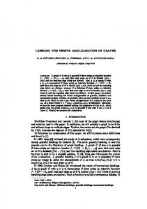
2.1 Amalgamation as a generalisation operation Amalgamation is one of the main operations used in map generalisation. Its generic behaviour can be defined as the replacement of several features by a single one. It can refer to mainly two types of action: the fusion of two adjacent polygons usually due to their reclassification to a single theme, or the aggregation of several polygons which are initially not touching. In this report, we focus more on the second problem, which presents a more difficult challenge, because neither the choice of the features to be amalgamated nor the construction of the shape of the resulting amalgam are straightforward. Depending on the scale reduction targeted and the specifications of the product, the features that require amalgamation vary. It affects the types of features that can be amalgamated, the distance threshold under which features should be amalgamated, the types of features that would prevent the amalgamation of others if they lie in the gap, etc. Figure 1 shows three map samples from different Ordnance Survey map series covering the same zone. The left one shows the 1:10k series, where all the buildings are represented individually. The centre image comes from the 1:25k series, and shows that amalgamation has been used to maintain a clear representation of the buildings. The Image on the right comes from the 1:50k series and shows a more dramatic level of amalgamation, required to keep the level of detail consistent with the scale targeted (see (10) for a discussion on the amount of object reduction needed through scale reduction).
Figure 1. Building amalgamation. Previous research on amalgamation algorithms mainly followed two lines. One is the use of morphologic operators (expand then shrink) (see (11), (12, (13)). They are particularly adapted to raster data. The other trend is to use a Delaunay triangulation to provide explicit spatial relationships between features and guide the amalgamation process (14), (15). These techniques are used in the context of vector data.
223
In this paper, we study the requirements for algorithms to support amalgamation of topographic data in order to generate topographic maps between 1:25k and 1:100k. We focus on data in vector format, which allow the use of triangulation based techniques. The triangulation will be necessary for other generalisation operations (especially displacement), so a common structure for spatial analysis would be convenient. Morphologic operators are very hard to fully control. They generate global solution with no easy local tuning. For all these reasons, the morphologic operators are not addressed further in this paper. We think they are not flexible enough for our purpose. 2.2 Amalgamation among other generalisation operators Amalgamation is mainly used to reduce proximity conflicts. A proximity conflict occurs when gaps between features are too small to be perceived. This occurs during scale reduction. Scale reduction by a simple zoom out reduces everything: the features and the gaps between them. So some of the gaps are going to get smaller than the human eye can perceive. In addition, scale reduction can be an indirect cause for the gaps getting too small. Scale reduction may necessitate to apply other algorithms (like enlargement and displacement), that would fill the gaps between objects. Amalgamation solves the small gaps problem by eliminating them, therefore merging the features together. But amalgamation is used in competition with displacement, which takes the reverse action: increase the gap between features until they can be visually distinguished. Shrinking is also a possibility to increase the gap between features. Figure 2 shows the main generalisation operations involved to solve the size and proximity conflicts. Other operations, like shape simplification, may have marginal effects on them, but they are not used to solve these conflicts. The plain green arrows show that an operation can be used to reduce or solve a particular type of conflict. The dotted green arrow means the same, except that the operation may not be powerful enough to solve the conflict, i.e. the amalgamation of two very small objects can generate a polygon which is still too small or too narrow. Red arrows show frequent (expected) bad effects on an operation. For example, moving a feature away from feature A can make it closer to Feature B, creating a new conflict.
Figure 2. Operations and conflicts. The sad thing is that we often prefer the operations that have bad side effects than the other ones. Amalgamation and elimination are modifications which are immediately noticeable on a map. Enlargement, shrink or displacement, when used wisely are much more difficult to spot, and therefore preferred. This means that we use amalgamation only when the shrink and displacement are not applicable, or can not solve the proximity conflict. Amalgamation is particularly useful when it solves two conflicts at once: group two close small features together to solve the size and proximity conflict. 2.3 Amalgamating what? Amalgamation is used to unify several area features. This operation is rarely needed at large scale, where distinct features tend to be kept individually. It starts to be very useful at medium scales (1:25 000 to 1:100 000). At these scales, the main two dimensional features shown in topographic maps are buildings, water bodies and vegetation (mainly forest). We will restrict our study to these three types of features. Buildings are very different from the other two. They are mainly small features, with distinctive shapes (orthogonal), and often grouped in dense clusters. On the other hand, forests or lakes/ponds, are often large, and distant from each other. This means that amalgamation is required for buildings at larger scales than it is needed for forests and water.
224
Figures 1 (in paragraph 2.1 above) and Figures 3 and 4 below, show examples of maps extracts, taken from Ordnance Survey maps series (10k, 25k, and 50k). They are not shown to scale, but in such a way that we can compare easily the evolution of the features through the scale reduction. For buildings (Figure 1), the amalgamation is quite dramatic. At 1:25k, few buildings have kept their individual character. At 1:50k, buildings are only shown by large amalgams.
Figure 3. Forest amalgamation. For the forests, 3 shows that the extent of the features varies very little between the 10k and the 25k Map series. The main difference seems to be in the classification of the polygons. Comparing the 10k and the 50k series shows that the smallest features have been omitted, some small ones have been enlarged and/or displaced, but no amalgamation took place (on the feature at the bottom of the picture, displacement was preferred). The main difference is that the adjacent features with similar types of vegetation have been merged. In fact for the forest type, amalgamation occurs at smaller scales to represent forest areas made of lots of fragmented parcels.
Figure 4. Hedge amalgamation. The exception is for hedges. They are relevant at such scales, but are often fragmented in the real world (for example to let a path or a small river go through), and therefore in the original database. The detail of the hedge may not be significant at the target scale while the hedge itself is. Therefore amalgamation is needed. An example of hedge amalgamation is shown in Figure 4.
225
We have distinguished water bodies from other natural land coverage because they can have particular functions which influence the way they should be generalised, and especially the way they should be amalgamated. In OS MasterMap®, most of the water bodies are represented by polygons. Some of them represent flowing water or drainage bodies. In this case, from a functional point of view, they should be seen as linear components of an hydrologic network. Amalgamation in this case should be limited to features that are contiguous in the network sense. Then it creates a polygon that is still functionally linear. If you amalgamate features that are not contiguous in the network, then you produce a polygon that has no linear function, and can be seen as an inconsistency in the network. Other water bodies that have a static function (water storage), are truly two dimensional objects, that can be amalgamated together. The first step before amalgamating water bodies is to classify them as functionally linear or area, and build an hydrologic network. Research has been done already on that issue (16). Figure 5 shows the representation of a fish farm in OS MasterMap®, and its depiction in the 25k and 50k Ordnance Survey Map series. The basins are amalgamated together but never with the river itself, whatever the proximity might be. The polygons part of the river play the role of obstructing features in the constitution of clusters of basins.
a) Initial (from OS MasterMap®)
b) 25k
c) 50k
Figure 5. Water bodies amalgamation. 3.
MAIN TYPES OF AMALGAMATION
This section proposes a classification for the amalgamation operations. The classification below is an attempt to identify different families of amalgamation algorithms. They have been deduced from observation of Ordnance Survey large and medium scales maps and data. Therefore, this classification, to be complete, needs to be extended to cover small scales and other mapping styles (from other map producers). 3.1 Amalgamation with displacement This type of amalgamation involves the displacement of the features toward each other and then amalgamate them. The displacement can be shared by the features, or limited to one of them. Usually, the bigger the feature the more resistant to displacement, so we tend to displace the smallest feature. The displacement can be full or partial. We call a full displacement a displacement that leads to the features touching or overlapping. In this case a merging is enough to complete the amalgamation. If the displacement only makes them closer, then it must be followed by an amalgamation of the other type (by bridging the features, see next section). The amalgamation by displacement does not increase the area occupied by the theme of the amalgamated features, or at least less than other methods. It also frees some space on the side of the displaced object which is opposite to the displacement direction. The main drawback of this method is that it changes the position of the features, which affects the spatial relationships with the neighbouring features. Figure 6 shows examples of amalgamation with displacement on buildings in urban area. Note that moving large features is not wise, it can create conflicts in regions outside the amalgamation area.
226
Figure 6. Amalgamation with displacement.
Figure 7. Bridging amalgamation of buildings.
3.2 Amalgamation by bridging features It can also be necessary to amalgamate two (or more) features without having to displace them. This is particularly useful when the features are large, or resistant to displacement for any other reason. In such a case, the amalgamation consists in bridging the features. The way the bridging is done depends on the nature of the features, it is important to preserve the shape specificity of the feature type. For example, bridging buildings could be done by adding a corridor, while two lakes should be joined using a patch with curved boundaries. Figure 7 and 8 illustrate this type of amalgamation for buildings and hedges respectively. The main advantage of this method is that it preserves the position of the features. The drawback is that it increases the density of the theme, which increases the overcrowding effect.
Figure 8. Bridging amalgamation for hedges.
3.3 Amalgamation by flooding the features This consists in replacing a group of features by a single polygon. The boundary of the resulting polygon are related to the extent of the initial group rather than the geometry of the initial features. This is useful to cope with dense areas of small objects, like buildings in urban areas (Figure 9). It would also be useful at small scales for forest when a forestry area is made of lots of small patches. 3.4 Amalgamation by sampling This consists in reducing the number of elements in a group of features. This is used when the objects are too small, and have a particular shape (nearly a symbol), that would be lost if another amalgamation technique was used. This is useful for small groups of houses for example. This is often referred in generalisation as typification (17, (18), (19). It is not properly an amalgamation, but we can not exclude it from our study because it is an alternative solution to solve the same problem. It’s an alternative to the amalgamation when the detached character of a group of features needs to be preserved. Figure 10 below illustrates the need for this type of operation.
227
Figure 9. Flooding Amalgamation.
4.
Figure 10. Examples of the different types of amalgamation.
ALGORITHM REQUIREMENTS FOR AUTOMATIC AMALGAMATION
In this section, we propose a list of algorithms that should enable us to tackle most of the amalgamation problems to derive mid-scale maps from detailed databases. Although the study relied only on the analysis existing OS products, we believe other detailed geographic databases will contain data that require similar treatments. Therefore, this list is a “wish list” for generalisation functionalities that we would like to see available in GIS. The first subsection addresses the requirements to actually detect where amalgamation should take place. The second subsection addresses the construction of the shape of the amalgam. 4.1 Choosing the features to amalgamate We usually amalgamate features when they are too close to each other and can’t be displaced or shrunk. This looks straightforward, but in fact the difficulty is to decide when to search for the objects that should be amalgamated. Looking for objects too close together in the initial state, or after enlargement, or after displacement, or after a combination of different algorithms would come up with different solutions. The practical solution consists in amalgamating whatever is too close after having applied the other algorithms. But this would probably lead to amalgamating objects that were not that close initially, which would look like a strange choice when evaluating the result. Another practical solution would be to start with amalgamating objects that are too close, with no hope of conflict resolution by other means. But this can lead to big objects which would be very hard to move later if required due to the proximity of features of other types. A sensible solution would be to detect in the initial state the candidates for amalgamation, and amalgamate these ones later if required. In order to detect and maintain these groups of features suitable for amalgamation, we need spatial structures to represent neighbourhood relationships between features. We propose to use two structures for this: a Triangulation to represent the direct neighbourhood of each feature, and a simple graph to represent groups of features. The graphs representing the groups would be deduced from the Triangulation. 4.1.1 Triangulation The triangulation is the key component for the amalgamation methods that we propose below. It helps the detection of the groups of features that need to be amalgamated, and it can also help the amalgamation itself. Triangulation is widely used in the generalisation context to represent the proximity relationships between features (20), (14), (21). We need to model the triangulation in robust and flexible way, to be able to use it at different stages of the generalisation process, and for different purposes. We propose to build a constrained triangulation based on the vertices of each feature of the initial data. The constraint is that each edge part of the geometry of a feature should be matched by an edge of the triangulation. Figure 11 below shows the result of such a triangulation on an urban block (partition of space delimited by a cycle of streets). This triangulation has been generated using Triangle © - VII/1996 School of Computer Science Carnegie Mellon University, written by Jonathan Richard Shewchuk.
228
4.1.2 Graph From the triangulation, it is easy to deduce some graphs that represent groups of close features. A good representation of these groups would be by a graph within which each node corresponds to a feature, and each link to the proximity relationship between the features represented by the two nodes connected by the link. Each link should be attributed with the minimum distance between the features.
Figure 11. Triangulation inside an urban block.
Figure 12. Automatic grouping of buildings.
The method for constructing the groups should probably depend on which amalgamation algorithm is targeted. We propose a method to build groups of buildings and roads which will support a flooding algorithm, discussed in the next section. This grouping method is based on two thresholds. A first threshold specifies under which minimum distance should two buildings belong to the same group. The second one specifies under which minimum distance should a road section be linked to a building. This second threshold will be dependant on the width of the symbol of the road at the target scale, while the first one relates to the minimum separation necessary to distinguish two close features at the target scale. To construct the groups, we start from one building feature, build the corresponding node, look for a neighbour close enough to be integrated in the same group (according to the relevant threshold). If we find one, we create the corresponding node and the link with the node from which it has been selected. If the newly added feature is close to other features of the same group, a link is added between their respective nodes. Then we carry on looking for another feature close to one of the features of the group. We expand the group in that way until no other feature lies close enough to the group. Then we choose another feature and start building another group, and so on. Note that when looking for a close neighbour from the group, only the buildings of this group are considered, not the roads. Otherwise, it would group buildings far away for each other, if they are both close to two distant parts of the same street section. Figure 12 shows the result of this algorithm on the same urban block. We have used 15 meters for both thresholds, which resulted in the detection of four groups. Note that there is only one node for each street section, which makes the links look strange, but each link is attributed with the correct minimum distance between the two features they connect. 4.2 Amalgamation algorithms proposed In this section, we specify a set of tools that could be needed to achieve amalgamation in the context of the automatic generalisation of topographic data. This set is of course not exhaustive, but should provide a good range to allow to tackle the most common amalgamation requirements. 4.2.1 Flooding amalgamation We propose to try two different techniques to amalgamate features of a given type. The first one (growing tide) gradually increases the amalgam until covering all the footprints of the original features, while the second (decreasing tide) starts by filling a whole region and inserts holes where significant areas don’t contain any feature. Growing tide is essential for amalgamating buildings for small scales outside the city centre. Decreasing tide will be more efficient to amalgamate buildings in city centres, and can also be useful for amalgamating other types of features.
229
4.3 Growing Tide The aim of this algorithm would be to amalgamate buildings, without completely filling up the space. It would be especially useful where buildings are organised in a row alongside a road, with no direct special constraint on their opposite side (back garden). In such a case, the extent of the amalgam can be generated from the extent of the road symbol. 4.3.1 Grouping criteria ! Distance between buildings ( threshold) ! Compatibility between the feature types 4.8.2 Parameters for the grouping procedure ! Maximum distance for amalgamating ! Minimum size for showing a feature ! Clusters of amalgamable types 4.8.3 Grouping technique ! Build a triangulation between all the amalgamable and obstructing features ! Select the edges of the triangulation that link to amalgamable objects, shorter than the minimum distance parameter. ! Group the features connected by the selected edges. 4.8.4 Amalgamation technique Here we can reuse the principles from (14) based on the triangulation. Every triangle linking two features of the cluster should be filled if one of the bridging edges is associated with a distance inferior to the threshold (maximum distance for amalgamation). Once this is done, the refinement using Bezier curve could be used to enhance the visual rendering. Finally, this technique may lead to holes, and possibly too narrow bridges. Holes too small should be filled, and bridges too narrow should be discarded if they don’t disconnect the cluster, widened otherwise. 4.8.5 Parameters for the amalgamation algorithm ! Maximum distance for amalgamating ! Minimum width (for bridges) ! Minimum size for holes
231
4.9 Linear amalgamation Linear amalgamation would aim at amalgamating features which form a linear pattern. This would be useful for hedges, which are often fragmented into patches of trees, while having a strongly linear structure. This would be like a bridging algorithm with additional constraints. The main difference would be in detecting where it should be used. This requires an automatic recognition of pattern of features forming a linear shape. 5.
CONCLUSION
In this paper, we have studied the requirements for amalgamation algorithms for generalising topographic maps. Once the individual algorithms are implemented, work would be needed on the rules that govern their triggering. This is expected to be a mix of cartographic rules, and user specifications. At this point, the integration of these algorithms with the other types of algorithms like displacement, elimination or shrink would need to be studied. The set of algorithms that we have specified should enable us to perform a wide range of amalgamation, for different feature types, and different scales. This is a first step to perform on demand generalisation. The next step will be to link the user requirements, through map specifications, to the choice of algorithms and parameters that need to be applied to the data. This requires a two-sided study: into what the user might require, and into how he might ask for it. The first side of the study is needed to make sure that we address the user needs, the second to make sure that the elements that will decide of the level of amalgamation of the different feature types are specified by the user (in the most intuitive way). This study has only addressed amalgamation. We believe this has to be done for every type of generalisation operations. Some of them have been widely studied and probably just need a recapitulative report. Others require the design of new algorithms. One of the most critical one is probably the displacement of features. But simplifications of single features, network simplification, shrinking, still need some work to make sure we have the required algorithms to cover a large range of generalisation specifications. We will also need to rework on the amalgamation side when addressing the evaluation issues. Evaluation is important to validate the generalisation process, and to inform the user of what level of amalgamation has been performed on the data. 6. [1] [2] [3] [4] [5] [6] [7] [8] [9] [10] [11] [12] [13] [14]
REFERENCES Douglas, D.H. and Peucker, T.K. (1973). Algorithms for the reduction of the number of points required to represent a digitized line or its caricature. The Canadian Cartographer. Vol. 10. 112-122. Brassel, K.E. and Weibel, R. (1988). A Review and Framework of Automated Map Generalization. Int. Journal of Geographical Information Systems, 2(3): 229-244. Nyerges, T. L. (1991). Representing geographical meaning. Map Generalization: Making rules for Knowledge Representation. Edited by Buttenfield and McMaster, Essex, Longman Scientific & Technical, pp: 59-85. Beard, K., and Mackaness, W. (1991). Generalization Operations and Supporting Structures. Auto-Carto 10: Technical Papers of the 1991 ACSM-ASPRS Annual Convention. Baltimore: ACSM-ASPRS, 1991. 6: 29-45 McMaster, R.B. and Shea, S (1992). Generalization in Digital Cartography. AAG, Washington, D.C. Buttenfield, B. (1991). A rule for describing line feature geometry, Map Generalization, edited by Buttenfield and McMaster, Longman Scientific & Technical, pp 101-171. Ruas, A. and Mackaness, W.A. (1997). Strategies for Urban Map Generalisation. In International Cartographic Conference, volume III, pp 1387-1394. Lamy, S., Ruas, A., Demazeau, Y., Jackson, M., Mackaness, W.A., and Weibel, R. (1999). The Application of Agents in Automated Map Generalisation. Proceedings of the 19th International Cartographic Conference. Ottawa), 1225-1234. Ware, M., Jones, C. (1998). Conflict Reduction in Map Generalization Using Iterative Improvement, GeoInformatica 2(4), 383-407. Töpfer, F. and Pillewizer, W., 1966. The Principles of Selection. The Cartographic Journal, Vol. 3, No. 1, pp 10-16. Schylberg, L., 1993, “Computational methods for generalisation of cartographic data in a raster environment”, PhD Thesis, Department of Geodesy and Photogrammetry, Royal Institute of Technology, Stockholm. Su, B., Li, Z., Lodwick, G. and Müller, J-C., 1997, “Algebraic models for the aggregation of area features based upon morphological operators”, International Journal of GIS, 11:3, 233-246. Cámara, M.A.U., Francisco, F.J.A., 2000, “Mathematical morphology applied to raster generalisation of urban city block maps”, Cartographica, 37:1, 33-48. Jones, C.B., Bundy, G.Ll. and Ware, J.M., 1995, “Map generalisation with a triangulated data structure”, Cartography and GIS, 22:4, 317-331.
232
[15] [16] [17] [18] [19] [20] [21] [22] [23]
Peter, B. and Weibel, R., 1999, “Using vector and raster-based techniques in categorical map generalisation”, presented at 3rd ICA Workshop on Progress in Automated Map Generalisation. Regnauld, N., Mackaness W.A., Greenwood, J., “Creating a hydrologic network from its cartographic representation“, to be published. Ormsby, D. and Mackaness, W., 1999, “The development of phenomenological generalisation within an objectoriented paradigm”, Cartography and GIS, 26:1, 70-80. Regnauld, N., 2001, “Contextual Building Typification in Automated Map Generalization”, Algorithmica, 30:2, pp 312-333. Sester, M., 2003, “Optimising approaches for generalisation and data abstraction”, to appear in International Journal of GIS: Special Issue on Map Generalisation. DeLucia, A. and Black, R.T., 1987, “A comprehensive approach to automatic feature generalisation”, Proceedings of 13th International Cartographic Conference, 173-191. Ruas, A., 1998, “A method for building displacement in automated map generalisation”, International Journal of GIS, 12:8, 789-803. Boffet, A., 2001, Méthode de création d'information multi-niveaux pour la généralisation cartographique de l'urbain, PhD Thesis from the Université de Marne la Vallée. Lichtner, W., 1979, “Computer-assisted processes of cartographic generalisation in topographic maps”, GeoProcessing, 1, 183-199.
233
ALGORITHMS FOR THE AMALGAMATION OF TOPOGRAPHIC DATA Regnauld, N. Ordnance Survey, Research and Innovation, Romsey Road, Southampton SO16 4GU, United Kingdom. E-mail:
[email protected] Biography Nicolas Regnauld did a PhD at the Institut Geographique National (Paris) from 95 to 98. He worked on building typification, i.e. the reduction of the number of buildings on a map while preserving the distribution pattern. From 1998 to 2001, he has been working at the University of Edinburgh on the EU funded project AGENT, aiming at developing a generic platform for automated generalisation. Since march 2002, he is working at the research department of Ordnance Survey (UK), in charge of the generalisation team.
234