other words, each Ïij contains an edge eij such that ei1 ei2 ...eil forms a path from v to s. ...... 108. Lemma 6.5.4. The radius R(TF ) of TF is at most 2 · OPT. Proof. ..... Conference on Theory and Applications of Models of Computation (TAMC), pp ...
ALGORITHMS FOR WIRELESS SENSOR NETWORKS by Min Kyung An
APPROVED BY SUPERVISORY COMMITTEE:
D. T. Huynh, Chair
Farokh B. Bastani
Weili Wu
S. Q. Zheng
c 2013 Copyright Min Kyung An All rights reserved
Dedicated to my family.
ALGORITHMS FOR WIRELESS SENSOR NETWORKS
by
MIN KYUNG AN, BS, MS
DISSERTATION Presented to the Faculty of The University of Texas at Dallas in Partial Fulfillment of the Requirements for the Degree of
DOCTOR OF PHILOSOPHY IN COMPUTER SCIENCE
THE UNIVERSITY OF TEXAS AT DALLAS August 2013
ACKNOWLEDGMENTS Most of all, I would like to express my deepest appreciation to my supervising professor, Dr. Dung T. Huynh. I have been extremely lucky to have him as my supervisor. Without his guidance and persistent help, this dissertation would not have been possible. He cared so much about my work, constantly gave me encouragement, and provided advice throughout my time as his student. He also taught me how to do research well, how to improve my writing skills, and how to work well in a team environment. Everything I learned from him will be my priceless experience for my future career as a computer scientist. I would like to thank my Ph.D. supervising committee members, Dr. Farokh B. Bastani, Dr. Weili Wu and Dr. S. Q. Zheng, for their time and valuable suggestions. In addition, I would like to send my gratitude to Dr. Andr´as Farag´o and Dr. Ding Z. Du for their support and advice. I am so thankful for my friends, Dr. Trac N. Nguyen and Nhat X. Lam, for being my great teammates during my Ph.D. studies. I would like to thank my love, Hyeonggak Kim, for always encouraging me and sharing this long journey with me. I would never have been able to finish my dissertation without him. He was always there cheering me up and stood by me through the good times and bad. Last but not the least, I am grateful to my parents, Jaegeun An and Jeongseon Yang, for their powerful support and encouragement throughout my academic career. I also would like to thank my sisters, Eunkyoung and Sukyoung, for being my great friends, and my little sister, Obong, and little twin brothers, Ohsan and Yongsan, for being my great math tutors. In addition, I owe my gratitude to my beloved grandmother and maternal grandfather for their v
endless love. I am sorry that I could not be there to say goodbye to them. Special thanks also should be given to my brother-in-law, Moonchang Yang, two cutest nieces, Jiyoon and Jihu, and my little adorable doggie, Joey. March 2013
vi
PREFACE This dissertation was produced in accordance with guidelines which permit the inclusion as part of the dissertation the text of an original paper or papers submitted for publication. The dissertation must still conform to all other requirements explained in the “Guide for the Preparation of Master’s Theses and Doctoral Dissertations at The University of Texas at Dallas.” It must include a comprehensive abstract, a full introduction and literature review, and a final overall conclusion. Additional material (procedural and design data as well as descriptions of equipment) must be provided in sufficient detail to allow a clear and precise judgment to be made of the importance and originality of the research reported. It is acceptable for this dissertation to include as chapters authentic copies of papers already published, provided these meet type size, margin, and legibility requirements. In such cases, connecting texts which provide logical bridges between different manuscripts are mandatory. Where the student is not the sole author of a manuscript, the student is required to make an explicit statement in the introductory material to that manuscript describing the student’s contribution to the work and acknowledging the contribution of the other author(s). The signatures of the Supervising Committee which precede all other material in the dissertation attest to the accuracy of this statement.
vii
ALGORITHMS FOR WIRELESS SENSOR NETWORKS Publication No. Min Kyung An, PhD The University of Texas at Dallas, 2013
Supervising Professor: D. T. Huynh
Data aggregation and Gossiping are two of the most crucial applications in Wireless Sensor Networks (WSNs) which have been the focus of many researchers. A main issue of data aggregation and gossiping is how to assign timeslots to nodes for interference-free data transmission. In this dissertation we study the problems of constructing minimum latency data aggregation schedules, known as the Minimum Latency Aggregation Scheduling (MLAS) problem, and gossiping schedules, known as the Minimum Latency Gossiping (MLG) problem, in two interference models, namely the graph model and the physical interference model also called the Signal-to-Interference-Noise-Ratio (SINR) model. We start by studying MLAS in the 2-dimensional (2D) graph model, and prove an Ω(log n) approximation lower bound in metric model (Moscibroda and Wattenhofer, 2005). We also propose a heuristic as well as an O(1)-approximation algorithm. We then study the MLAS problem in the 3-dimensional (3D) graph and SINR models, prove its NP-hardness and propose two O(1)-approximation algorithms. We then investigate the MLG problem in the 2D graph and SINR models, and prove its NP-hardness and propose an O(1)-approximation algorithm. viii
Along with the MLAS and MLG problems, we also investigate a related problem, namely the Minimum Channel Assignment (MCA) problem, whose main issue is to compute a minimum channel assignment that yields a strongly-connected communication graph spanning all nodes such that the nodes assigned to the same channel can communicate without interference in the 2D SINR model. We show the NP-hardness of the MCA problem, and propose two O(1)-approximation algorithms. Lastly, this dissertation contains a study of the Bounded-Degree Minimum-Radius Spanning Tree problem whose objective is to compute a spanning tree which satisfies certain constraints. Given a disk graph G = (V, E) and an integer constant ∆∗ ≥ 2, the problem is to construct a spanning tree T = (V, ET ⊆ E) of G such that the radius of T is minimized while the degree of any node in T is at most ∆∗ . We show that this problem is NP-complete, and introduce a (8, 4)-bicriteria approximation algorithm for the problem on unit disk graphs. We then introduce a bicriteria approximation algorithm for the problem on disk graphs.
ix
TABLE OF CONTENTS ACKNOWLEDGMENTS . . . . . . . . . . . . . . . . . . . . . . . . . . . . . . . . .
v
PREFACE . . . . . . . . . . . . . . . . . . . . . . . . . . . . . . . . . . . . . . . . .
vii
ABSTRACT . . . . . . . . . . . . . . . . . . . . . . . . . . . . . . . . . . . . . . . .
viii
LIST OF FIGURES . . . . . . . . . . . . . . . . . . . . . . . . . . . . . . . . . . . .
xiv
LIST OF TABLES . . . . . . . . . . . . . . . . . . . . . . . . . . . . . . . . . . . . .
xvi
CHAPTER 1 INTRODUCTION . . . . . . . . . . . . . . . . . . . . . . . . . . . .
1
1.1
Introduction . . . . . . . . . . . . . . . . . . . . . . . . . . . . . . . . . . . .
1
1.2
Problems in Wireless Sensor Networks . . . . . . . . . . . . . . . . . . . . .
1
1.2.1
Scheduling Problems . . . . . . . . . . . . . . . . . . . . . . . . . . .
2
1.2.2
Backbone Construction for Wireless Sensor Networks . . . . . . . . .
4
Outline of the Dissertation . . . . . . . . . . . . . . . . . . . . . . . . . . . .
5
1.3
CHAPTER 2 MINIMUM LATENCY DATA AGGREGATION SCHEDULE IN WIRELESS SENSOR NETWORKS . . . . . . . . . . . . . . . . . . . . . . . . . . . . .
8
2.1
Abstract . . . . . . . . . . . . . . . . . . . . . . . . . . . . . . . . . . . . . .
8
2.2
Introduction . . . . . . . . . . . . . . . . . . . . . . . . . . . . . . . . . . . .
9
2.3
Models and Definitions . . . . . . . . . . . . . . . . . . . . . . . . . . . . . .
11
2.4
Approximation Lower Bound . . . . . . . . . . . . . . . . . . . . . . . . . . .
13
2.5
Heuristic Algorithm with Non-Uniform Power Levels . . . . . . . . . . . . .
17
2.6
Nearly Constant Factor Approximation Algorithm with Uniform Power Level
20
2.6.1
Algorithm . . . . . . . . . . . . . . . . . . . . . . . . . . . . . . . . .
20
2.6.2
Analysis of Algorithm . . . . . . . . . . . . . . . . . . . . . . . . . .
23
2.7
Simulation Results . . . . . . . . . . . . . . . . . . . . . . . . . . . . . . . .
24
2.8
Conclusion . . . . . . . . . . . . . . . . . . . . . . . . . . . . . . . . . . . . .
26
CHAPTER 3 MINIMUM LATENCY AGGREGATION SCHEDULING PROBLEM IN INTERFERENCE-AWARE 3-DIMENSIONAL WSNS . . . . . . . . . . . . . 27 3.1
Abstract . . . . . . . . . . . . . . . . . . . . . . . . . . . . . . . . . . . . . . x
27
3.2
Introduction . . . . . . . . . . . . . . . . . . . . . . . . . . . . . . . . . . . .
27
3.3
Preliminaries . . . . . . . . . . . . . . . . . . . . . . . . . . . . . . . . . . .
32
3.3.1
3D Network Models . . . . . . . . . . . . . . . . . . . . . . . . . . . .
32
3.3.2
Problem Definition . . . . . . . . . . . . . . . . . . . . . . . . . . . .
34
3.3.3
NP-Hardness of the MLAS Problem in 3D WSNs . . . . . . . . . . .
34
3-Dimensional Space Filling . . . . . . . . . . . . . . . . . . . . . . . . . . .
34
3.4.1
Space Filling with Cubes . . . . . . . . . . . . . . . . . . . . . . . . .
35
3.4.2
Space Filling with Hexagonal Prisms . . . . . . . . . . . . . . . . . .
35
3.5
Constant Factor Approximation Algorithms . . . . . . . . . . . . . . . . . .
36
3.6
Analysis . . . . . . . . . . . . . . . . . . . . . . . . . . . . . . . . . . . . . .
40
3.6.1
Analysis of CBAS Algorithm . . . . . . . . . . . . . . . . . . . . . . .
41
3.6.2
Analysis of HPBAS Algorithm . . . . . . . . . . . . . . . . . . . . . .
45
Conclusion . . . . . . . . . . . . . . . . . . . . . . . . . . . . . . . . . . . . .
46
3.4
3.7
CHAPTER 4 MINIMUM LATENCY GOSSIPING IN WIRELESS SENSOR NETWORKS . . . . . . . . . . . . . . . . . . . . . . . . . . . . . . . . . . . . . . . . . 47 4.1
Abstract . . . . . . . . . . . . . . . . . . . . . . . . . . . . . . . . . . . . . .
47
4.2
Introduction . . . . . . . . . . . . . . . . . . . . . . . . . . . . . . . . . . . .
47
4.3
Preliminaries . . . . . . . . . . . . . . . . . . . . . . . . . . . . . . . . . . .
51
4.3.1
Network Model . . . . . . . . . . . . . . . . . . . . . . . . . . . . . .
51
4.3.2
Problem Definition . . . . . . . . . . . . . . . . . . . . . . . . . . . .
53
4.4
NP-Hardness . . . . . . . . . . . . . . . . . . . . . . . . . . . . . . . . . . .
54
4.5
Constant-Factor Approximation Algorithm . . . . . . . . . . . . . . . . . . .
56
4.5.1
Algorithm . . . . . . . . . . . . . . . . . . . . . . . . . . . . . . . . .
56
4.5.2
Analysis . . . . . . . . . . . . . . . . . . . . . . . . . . . . . . . . . .
60
4.5.3
Simulation . . . . . . . . . . . . . . . . . . . . . . . . . . . . . . . . .
63
Conclusion . . . . . . . . . . . . . . . . . . . . . . . . . . . . . . . . . . . . .
66
4.6
CHAPTER 5 CONNECTIVITY PROBLEM IN WIRELESS SENSOR NETWORKS IN THE SINR MODEL . . . . . . . . . . . . . . . . . . . . . . . . . . . . . . . . 67 5.1
Abstract . . . . . . . . . . . . . . . . . . . . . . . . . . . . . . . . . . . . . .
67
5.2
Introduction . . . . . . . . . . . . . . . . . . . . . . . . . . . . . . . . . . . .
67
xi
5.3
Preliminaries . . . . . . . . . . . . . . . . . . . . . . . . . . . . . . . . . . .
70
5.3.1
Network Model . . . . . . . . . . . . . . . . . . . . . . . . . . . . . .
70
5.3.2
Problem Definition . . . . . . . . . . . . . . . . . . . . . . . . . . . .
70
5.4
NP-Hardness . . . . . . . . . . . . . . . . . . . . . . . . . . . . . . . . . . .
71
5.5
Minimum Channel Assignment on 2-D Grid Networks . . . . . . . . . . . . .
73
5.6
Constant-Factor Approximation Algorithms . . . . . . . . . . . . . . . . . .
76
5.6.1
Tree Construction . . . . . . . . . . . . . . . . . . . . . . . . . . . . .
76
5.6.2
Algorithms . . . . . . . . . . . . . . . . . . . . . . . . . . . . . . . .
77
5.6.3
Analysis . . . . . . . . . . . . . . . . . . . . . . . . . . . . . . . . . .
81
5.6.4
Simulation Results . . . . . . . . . . . . . . . . . . . . . . . . . . . .
83
Conclusion . . . . . . . . . . . . . . . . . . . . . . . . . . . . . . . . . . . . .
84
5.7
CHAPTER 6 BOUNDED-DEGREE MINIMUM-RADIUS SPANNING TREES IN WIRELESS SENSOR NETWORKS . . . . . . . . . . . . . . . . . . . . . . . . . . . . . 86 6.1
Abstract . . . . . . . . . . . . . . . . . . . . . . . . . . . . . . . . . . . . . .
86
6.2
Introduction . . . . . . . . . . . . . . . . . . . . . . . . . . . . . . . . . . . .
86
6.3
Preliminaries . . . . . . . . . . . . . . . . . . . . . . . . . . . . . . . . . . .
89
6.3.1
Network Model . . . . . . . . . . . . . . . . . . . . . . . . . . . . . .
89
6.3.2
Problem Definition . . . . . . . . . . . . . . . . . . . . . . . . . . . .
90
6.3.3
NP-Completeness of the BDMRST Problem . . . . . . . . . . . . . .
90
Bounded-Degree Minimum-Radius Spanning Tree on Unit Disk Graphs . . .
91
6.4.1
Algorithm . . . . . . . . . . . . . . . . . . . . . . . . . . . . . . . . .
91
6.4.2
Analysis . . . . . . . . . . . . . . . . . . . . . . . . . . . . . . . . . .
99
6.4
6.5
Bounded-Degree Minimum-Radius Spanning Tree on Disk Graphs . . . . . . 103 6.5.1
Algorithm . . . . . . . . . . . . . . . . . . . . . . . . . . . . . . . . . 103
6.5.2
Analysis . . . . . . . . . . . . . . . . . . . . . . . . . . . . . . . . . . 105
CHAPTER 7 CONCLUSIONS . . . . . . . . . . . . . . . . . . . . . . . . . . . . . 109 7.1
Summaries . . . . . . . . . . . . . . . . . . . . . . . . . . . . . . . . . . . . . 109
7.2
Future Works . . . . . . . . . . . . . . . . . . . . . . . . . . . . . . . . . . . 110 7.2.1
Scheduling with Power Control . . . . . . . . . . . . . . . . . . . . . 110 xii
7.2.2
3-Dimensional Wireless Networks . . . . . . . . . . . . . . . . . . . . 111
7.2.3
Mobile Networking and Computing . . . . . . . . . . . . . . . . . . . 111
REFERENCES . . . . . . . . . . . . . . . . . . . . . . . . . . . . . . . . . . . . . . . 112 VITA
xiii
LIST OF FIGURES 2.1
For any α > 1, even there is no collision, v1 and v3 cannot send data simultaneously because v2 and v4 are interfered by v3 and v1 , respectively. . . . . . . . . .
12
2.2
The corresponding MDAS instance . . . . . . . . . . . . . . . . . . . . . . . . .
14
2.3
Network partition . . . . . . . . . . . . . . . . . . . . . . . . . . . . . . . . . . .
20
2.4
Schedules computed by SDA, MDAB, and Cell Coloring where α = 1 and nodes have a uniform power level. (a) Unit Disk Graph (b) SDA schedule (c) MDAB schedule (d) Cell Coloring schedule. Black nodes represent dominators, and gray nodes represent connectors. . . . . . . . . . . . . . . . . . . . . . . . . . . . . .
25
3.1
Transmission ball and interference ball of u . . . . . . . . . . . . . . . . . . . . .
33
3.2
Space-filling convex polyhedra . . . . . . . . . . . . . . . . . . . . . . . . . . . .
35
3.3
(a) 6-labeling (k = 1) (b) Space-filling with 6-labeling . . . . . . . . . . . . . . .
36
3.4
(a) 60-labeling (k = 2) (b) Space-filling with 60-labeling
. . . . . . . . . . . . .
36
3.5
216-labeling (k = 3) . . . . . . . . . . . . . . . . . . . . . . . . . . . . . . . . .
37
3.6
The inscribed ball that touches each face of the cube. . . . . . . . . . . . . . . .
43
4.1
The corresponding geometric MLG instance . . . . . . . . . . . . . . . . . . . .
54
5.1
The corresponding geometric MCA instance . . . . . . . . . . . . . . . . . . . .
72
5.2
(a) 1-labeling (l = 1) (b) 7-labeling (l = 2) (c) 19-labeling (l = 3) (d) Tessellation with 19-labelin . . . . . . . . . . . . . . . . . . . . . . . . . . . . . . . . . . . .
79
6.1
Example of an MIS that consists of black nodes. c is the center node of G. . . .
92
6.2
Example of the construction of a CDS which consists of the set of nodes that are connected by bold lines. Black nodes represent dominators and gray nodes represent dominatees. . . . . . . . . . . . . . . . . . . . . . . . . . . . . . . . . .
92
Example of the construction of an initial tree TI whose edges are represented by bold lines. Black nodes represent dominators, gray nodes represent connectors, and white nodes represent dominatees. . . . . . . . . . . . . . . . . . . . . . . .
93
Example of RRC (Phase 1). Black nodes represent dominators, gray nodes represent connectors, and white nodes represent dominatees. . . . . . . . . . . . . .
94
Partitioning u’s broadcasting disk into 8 sectors. . . . . . . . . . . . . . . . . . .
94
6.3
6.4 6.5
xiv
6.6
Example of BTC (Phase 2). Black nodes represent dominators, and gray nodes represent connectors. . . . . . . . . . . . . . . . . . . . . . . . . . . . . . . . . .
99
6.7
Example of Phase 3 for the case |Cu | ≥ 1 with ∆∗ = 4. Black nodes represent dominators, gray nodes represent connectors, and white nodes represent dominatees. 99
6.8
radian, θ0 = π2 radian, Example of sec(u, θ, r) and sec(u, θ00 , 2r), where θ = 2π 8 5π 00 0 0 and θ = θ + θ + θ = 4 radian. . . . . . . . . . . . . . . . . . . . . . . . . . . 100
6.9
Bounding the number of connectors in a sector. Radius of innermost circle is r, radius of dotted circle is 1.5r, and radius of outermost circle is 2r. . . . . . . . . 101
6.10 Partitioning um ’s broadcasting disk into m concentric circles (disks) centered at um . . . . . . . . . . . . . . . . . . . . . . . . . . . . . . . . . . . . . . . . . . . . 104 6.11 Example of Local Tree Construction (LTC-DG) with ∆∗ = 4. Black nodes represent dominators, and white nodes represent dominatees. Nodes filled with upward diagonals are dominatees that are selected as local sinks. . . . . . . . . . . . . . 105 6.12 Bounding the number of connectors. . . . . . . . . . . . . . . . . . . . . . . . . 107
xv
LIST OF TABLES 2.1
Average length of schedules computed by SDA, MDAB, and Cell Coloring algorithms . . . . . . . . . . . . . . . . . . . . . . . . . . . . . . . . . . . . . . . . .
25
4.1
Latencies of Algorithm 8 in Graph Model . . . . . . . . . . . . . . . . . . . . . .
65
4.2
Latencies of Algorithm 8 in SINR Model . . . . . . . . . . . . . . . . . . . . . .
65
5.1
The size of channel assignments produced by SBCA and HBCA algorithms . . .
84
xvi
CHAPTER 1 INTRODUCTION 1.1
Introduction
Wireless Sensor Networks consist of wireless sensor devices whose power source is usually in the form of a battery. These devices, which are also called wireless nodes, turn on their power to emit radio signals, or turn it off to conserve energy. The wireless sensor networks have been hugely welcomed into our lives with their capabilities to communicate between sensor nodes, to monitor nearby environmental conditions, and so on, using their radio signals. Such capabilities have found applications in various areas including health (to monitor disabled patients), military (for command, control, communication, computing, intelligence, surveillance, reconnaissance, and targeting system), home monitoring, and so on. Recent advances in such wireless sensor networks have led to the remarkable development of modern sensor devices over traditional ones. However, these tiny devices still have limited energy resources. This Ph.D. dissertation has focused on overcoming such hardware limitation of wireless sensor networks, and aimed to provide certain desired features of wireless sensor networks such as energy efficiency, low interference, and connectivity by designing efficient algorithms for optimization problems in wireless sensor networks.
1.2
Problems in Wireless Sensor Networks
This dissertation focuses on several problems in wireless sensor networks such as • scheduling of wireless sensor nodes, and • computing infrastructure for wireless sensor networks. 1
2
In the literature, wireless sensor networks are commonly modeled as graphs where any two nodes are connected via a communication edge if they are covered by each other’s transmission range. When considering problems on such networks, choosing the interference model is a crucial step. While a substantial amount of research results have been obtained for the graph-based interference model, recently, several researchers have started investigating the problems in the more realistic physical interference model, also known as Signal-toInterference-Noise-Ratio (SINR), which, unlike the graph model, more adequately captures real world phenomena. As the SINR model has been introduced only recently, few works exist and algorithms that guarantee theoretical performances are scarce. The studies in this dissertation have been done for both interference models, and following is a summary of the problems studied. 1.2.1
Scheduling Problems
When a node sends its data to other nodes by emitting its radio signal, the transmission can be interfered by signals concurrently sent by other nodes, and therefore it has to re-transmit. Thus, scheduling wireless sensor nodes by assigning them appropriate timeslots such that nodes in the same timeslot do not interfere with each other is an important approach to conserve energy. The scheduling problem has been investigated by several researchers as it can be used for well-known crucial applications in wireless sensor networks. This dissertation investigates the scheduling problem for other applications such as data aggregation and gossiping. Along with the problems of assigning timeslots to nodes, another related problem is to assign appropriate channels to the nodes so that a strongly-connected topology can be obtained. This problem is known as the Minimum Channel Assignment problem, and it has also been the focus of many researchers since it represents the theoretically achievable efficiency of MAC layer protocols (Moscibroda and Wattenhofer, 2006). This dissertation also investigates the channel assignment problem.
3 Data Aggregation Given a set of nodes on the plane, the objective of the problem is to assign appropriate timeslots to the sensor nodes to obtain a good (short) schedule by which data can be aggregated to a so-called base station (or sink ) without any collision or interference. Our first investigation of the problem has been done in the graph-based interference model. We have shown that there is no approximation algorithm having an approximation ratio better than Ω(log n) for the problem in the metric model (An et al., 2010a), where n is the number of nodes deployed, and proposed an O(1)-approximation algorithm for the problem in the uniform power model where all nodes are assigned a uniform transmission power level (An et al., 2011). We then extended our study to the SINR model, and showed the first NPhardness result in (Lam et al., 2011) and proposed two approximation algorithms with an O(1)-approximation ratios in the dual power model where the sensor nodes are assigned a high-power or low-power transmission level (An et al., 2012b). Subsequently, we focused on designing an algorithm that works in the graph-based interference model as well as the SINR model, and proposed a new approximation algorithm with an O(1)-approximation ratio in the non-uniform power model. This was the first O(1)-approximation algorithm in the non-uniform power model (Lam et al., 2013). Recently, we studied the problem in the more general 3-dimensional (3D) wireless sensor networks adopting both interference models, and proposed two O(1)-approximation algorithms which are the first results for 3D wireless sensor networks. Gossiping Given a set of nodes on the plane, the objective of the problem, which is also known as all-to-all broadcast, is to distribute the message of each node to all the other nodes in the network. Our approach in (An et al., 2010b) to solve the problem is to assign appropriate timeslots to the sensor nodes to obtain a good (short) schedule by which data can
4 be distributed without any collision or interference. We have studied the problem in the graph-based interference model and the SINR model. We have shown the first NP-hardness result in the SINR model, and proposed an O(1)-approximation algorithm that works in both interference models. In the collision-free graph model, i.e., the graph-based interference model concerning only collision, the approximation ratio is 224 which is currently the best ratio and is an improvement on the approximation ratio of 258 given by (Krzywdzinski, 2010). In the collision-interference-free graph model, i.e., the graph-based interference model concerning both collision and interference, and the SINR model, our results are the first O(1)-approximation algorithms.
Channel Assignment for Strong Connectivity Given a set of nodes on the plane, the problem is to compute a channel assignment that yields a strongly connected communication graph spanning all nodes such that sender nodes in the same channel can communicate with its receivers without interference in the SINR model. Here, the complexity measure is the number of channels used in the assignment, and the objective is to minimize it. In (An et al., 2012a), we have not only proved the first NPhardness result, but also proposed two approximation algorithms with O(1)-approximation ratios which are the first results in the literature.
1.2.2
Backbone Construction for Wireless Sensor Networks
A wireless network consists of wireless devices that communicate each other using wireless signals. Wireless Sensor Networks are one of such infrastructure-less wireless networks. Thus, given a graph which represents a wireless sensor network, it is desirable to compute e.g. a spanning tree which satisfies certain constraints on parameters such as node degree, diameter (or radius) or total cost, etc. Such subgraphs are useful because they can serve as a pre-defined network infrastructure for communication in wireless sensor networks.
5 Bounded-Degree Minimum-Radius Spanning Tree The problems of computing a spanning tree which satisfies certain constraints are known as constrained spanning tree problems in the literature, and we have studied one of such problems, namely the Bounded-Degree Minimum-Radius Spanning Tree problem. Given a disk graph G = (V, E) which represents a wireless sensor network and an integer constant ∆∗ ≥ 2, the objective of the problem is to construct a bounded-degree minimum-radius spanning tree T = (V, ET ⊆ E) of G such that the radius of T is minimized while the degree of any node in T is at most ∆∗ . We have studied the problem on disk graphs as well as unit disk graphs, while all existing works studied the problem in unit disk graphs only. We showed that the problem is NP-complete, and introduced an (8, 4)-bicriteria approximation algorithm for the problem on unit disk graphs which is a special case of disk graphs. This result is an improvement over the bound (10, 7) obtained in (Ghosh et al., 2011). We then introduced a bicriteria approximation algorithm that computes a spanning tree of a disk graph, and this is the first result for disk graphs in the literature.
1.3
Outline of the Dissertation
The rest of this dissertation is organized as follows. Chapter 2 studies the the problem of computing minimum-length schedules for data aggregation in the graph-based interference model. The result of this chapter was originally published in the paper entitled “Minimum Data Aggregation Schedule in Wireless Sensor Networks” in the Proceedings of the ISCA 23rd International Conference on Computer Applications in Industry and Engineering (CAINE 2010), and later extended for publication in the International Journal of Computers and their Applications (IJCA 2011). This chapter shows an Ω(log n) approximation lower bound for the metric model under assumption that the nodes in a network can have non-uniform power levels. In addition, it introduces a heuristic algorithm with non-uniform power levels
6 as well as a constant factor approximation algorithm with a uniform power level. It also compares the performances of the algorithms against the SDA algorithm proposed in (Chen et al., 2009). While Chapter 2 studies the problem of computing minimum-length schedules for data aggregation in 2-dimensional (2D) wireless sensor networks, Chapter 3 studies the problem in the more general 3-dimensional (3D) wireless sensor networks adopting both interference models, graph-based interference model and SINR model. This chapter proposes two O(1)approximation algorithms which are the first results for 3D wireless sensor networks. Chapter 4 discusses the problem of computing minimum-length schedules for gossiping in both graph-based interference model and SINR model. The result of this chapter was published in the paper entitled “Minimum Latency Gossiping in Wireless Sensor Networks” in the Proceedings of the International Conference on Wireless Networks (ICWN 2010). This chapter shows the first NP-hardness result in the SINR model, and proposes an O(1)-approximation algorithm that works in both interference models. In the collisionfree graph model, the approximation ratio is 224 which is currently the best ratio and is an improvement on the approximation ratio of 258 given by (Krzywdzinski, 2010). In the collision-interference-free graph model and the SINR model, the results are the first O(1)approximation algorithms. Chapter 5 concentrates on computing a channel assignment that yields a strongly connected communication graph spanning all nodes such that sender nodes in the same channel can communicate with its receivers without interference in the SINR model. The result of this chapter was published in the paper entitled “Connectivity in Wireless Sensor Networks in the SINR Model” in the Proceedings of the 20th Annual IEEE International Symposium on Modeling, Analysis and Simulation of Computer and Telecommunication Systems (MASCOTS 2012). This chapter shows the first NP-hardness result in the SINR model, and proposes two approximation algorithms with O(1)-approximation ratios, assuming the uniform power model, which are the first results in the literature.
7 Chapter 6 explores one of the constrained spanning tree problems, Bounded-Degree Minimum-Radius Spanning Tree (BDMRST) problem. This chapter studies the problem on disk graphs as well as unit disk graphs, while all existing works studied the problem in unit disk graphs only. It shows that the problem is NP-complete, and introduces a (8, 4)bicriteria approximation algorithm, which is an improvement over the bound (10, 7) obtained in (Ghosh et al., 2011), for the problem on unit disk graphs. It then introduces a bicriteria approximation algorithm that computes a spanning tree of a disk graph, and this is the first result for disk graphs in the literature. Chapter 7 contains some concluding remarks summarizing the studies of the chapters, and describing some open problems and future research directions.
CHAPTER 2 MINIMUM LATENCY DATA AGGREGATION SCHEDULE IN WIRELESS SENSOR NETWORKS 2.1
Abstract
Data aggregation is one of the crucial applications in Wireless Sensor Networks (WSNs). It therefore has been the focus of many researchers. An important issue concerning data aggregation is how to assign appropriate time slots to the nodes so that data transmission in the network is free of any collision and interference. As time efficiency and energy consumption are vitally important, a major problem is to find a minimum-length schedule that is collision-free and interference-free. In this chapter, we study the Minimum Data Aggregation Schedule (MDAS) problem in WSNs. While other studies of the MDAS problem consider only the collision-free model (e.g., (Annamalai et al., 2003; Chen et al., 2009; Du et al., 2006; Huang et al., 2007; Kesselman and Kowalski, 2006)), our objective is to construct schedules in which data transmission is both collision-free and interference-free. We prove an Ω (log n) approximation lower bound for the MDAS problem in the metric model (Moscibroda and Wattenhofer, 2005) under the assumption that the nodes in a network can have non-uniform power levels. In addition, we introduce a heuristic algorithm with non-uniform power levels, and a nearly constant factor approximation algorithm with a uniform power level whose latency is bounded by O(∆ + R), where ∆ is the maximum node degree of a network and R is the network radius. We compare their performances against the Shortest-Data-Aggregation (SDA) algorithm in (Chen et al., 2009). 8
9 2.2
Introduction
A Wireless Sensor Network (WSN) consists of a number of small-sized sensor nodes that monitor nearby environmental conditions and gather data. They communicate with each other through their radio signals. One of the main tasks of these sensor nodes is to collect data periodically and forward it to a destination called the sink node. This type of application is commonly known as data aggregation in the literature. Despite recent advances in sensing technology, small-sized sensors still have limited energy resources, and one of the main issues in WSNs research is to reduce energy consumption thereby extending the network lifetime. This issue is related with data aggregation since efficient data aggregation can decrease the overall energy consumption in a WSN. An interesting approach is to assign time slots to sensor nodes to obtain a good schedule so that sensor nodes can avoid unnecessary retransmission using their limited power. Since the data collection occurs periodically, reducing the latency of the schedule, that is, constructing schedules with a minimum number of time slots, is also a fundamental issue in WSN research. The problem of constructing minimum-length data aggregation schedules in the collisionfree transmission model of WSN’s has been the focus of many researchers. (Annamalai et al., 2003) developed a heuristic algorithm that constructs a tree with a schedule that assigns a code and a time slot to each node to communicate with its parent node. In (Du et al., 2006), an algorithm for finding a minimal-length schedule was proposed and it was claimed that there exists a schedule whose length is at most min{log2 ( |S|+2 ) + 1, 3 log3 ( 2|S|+3 ) + 2} for unit 3 5 disk graphs, where S is a set of source nodes that have data to be to sent to a sink node. Recently in (Chen et al., 2009), a (∆ − 1)-approximation algorithm for finding collision-free schedules with minimal length was designed, where ∆ is the maximum node degree of the network, and NP-hardness was also proved for the grid topologies. (Huang et al., 2007) introduced an algorithm based on maximal independent sets whose latency is bounded by 23R + ∆ − 18, where R is the network radius. As in WSNs, the problem of constructing
10 minimal-length schedules has also been studied in Wireless Ad Hoc Networks. For instance, (Kesselman and Kowalski, 2006) introduced an algorithm that consumes at most O (n log n) time slots. The algorithms in (Annamalai et al., 2003; Chen et al., 2009; Huang et al., 2007) assumed that each node has a uniform power level. On the other hand, (Du et al., 2006; Kesselman and Kowalski, 2006) designed their algorithms under the assumption that nodes can have non-uniform power levels. In contrast to data aggregation, broadcasting data from a source node (base station) to all the other nodes in the collision-free transmission model of WSNs has been more widely studied. Very early in the 1980s and 1990s, this problem was already investigated by many researchers (Alon et al., 1991; Bar-Yehuda et al., 1987; Bruschi and Del Pinto, 1997). In (Gandhi et al., 2003), it was proved that constructing a minimum-latency broadcast schedule is NP-hard and an algorithm whose schedule length is at most 648R was introduced. Later, (Banik and Radhakrishnan, 2007) produced broadcast schedules using three algorithms with latencies at most 24R−23, 16R−15, and R+O (log R), respectively. These three algorithms are based on connected dominating sets, k-independent sets, and node coloring. While only collision was considered in those papers, (Calinescu and Tongngam, 2008) and (Chen et al., 2007) focused on interference as well. Given a transmission power level d for each node, the interference range is defined as αd where α ≥ 1 is the interference factor. (Chen et al., 2007) introduced a heuristic algorithm that finds broadcast schedules for α > 1 based on breadth-first search trees. The authors claimed an O (α2 ) approximation ratio. Following (Chen et al., 2007), (Calinescu and Tongngam, 2008) presented an algorithm that produces an O (αR) schedule, where an O (α) approximation ratio was proved. In this chapter, we study the problem of computing minimum-length schedules for data aggregation in WSNs. As in (Calinescu and Tongngam, 2008; Chen et al., 2007), we consider the issues of interference as well as collision. We show an Ω (log n) approximation lower bound for the metric model under assumption that the nodes in a network can have non-uniform
11 power levels. In addition, we introduce a heuristic algorithm with non-uniform power levels as well as a nearly constant factor approximation algorithm with a uniform power level whose latency is bounded by O(∆ + R), where ∆ is the maximum node degree of a network and R is the network radius. This chapter is organized as follows. In Section 2.3, we describe our network model and define the Minimum Data Aggregation Schedule (MDAS) problem. Section 2.4 establishes an Ω (log n) approximation lower bound for the MDAS problem in the metric model. In Section 2.5, we introduce our heuristic, the Minimum Data Aggregation on Backbone tree (MDAB) algorithm. Section 2.6 contains the nearly constant factor approximation algorithm called Cell Coloring. In Section 6, we compare their performances against the SDA algorithm proposed in (Chen et al., 2009). Section 2.8 contains some concluding remarks.
2.3
Models and Definitions
A WSN is defined in the metric model as (V, D, p) (Moscibroda and Wattenhofer, 2005), where V represents a set of sensor nodes, D : V × V → R+ represents the distance function that satisfies the triangle inequality, and pmax : V → R+ is the maximum power level function. For a constant d > 0, let Rdu = {v|v ∈ V, D(u, v) ≤ d} denote the set of all nodes that can be reached by node u using the power level d. Let p : V → R+ , p(u) ≤ pmax (u), u ∈ V , be a power assignment function. Two nodes u, v can communicate only if they are v u in the coverage area of each other, i.e., u ∈ Rp(v) and v ∈ Rp(u) . In this case, there is an
undirected edge between u and v. (Note we assume the bidirectional model.) In this chapter we consider the collision-free model, where a collision (or conflict) is said u v to occur at a node w if there exist nodes u and v such that w ∈ Rp(u) ∩ Rp(v) . In this
work, however, we also consider the interference model as well. For a constant d > 0, let Fdu = {v|v ∈ V, D(u, v) ≤ αd} where α ≥ 1 is the interference factor, i.e., Fdu denotes the set of all nodes in the interference range of node u that is assigned the power level d. As defined
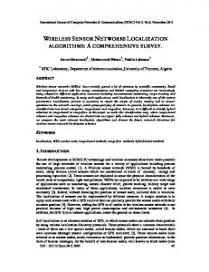
12 in (Calinescu and Tongngam, 2008), given a power assignment p, an interference is said to v u . (See Figure 2.1.) ∩ Fp(v) occur at a node w if there exists nodes u and v such that w ∈ Rp(u)
Figure 2.1. For any α > 1, even there is no collision, v1 and v3 cannot send data simultaneously because v2 and v4 are interfered by v3 and v1 , respectively. The Minimum Data Aggregation Schedule (MDAS) problem in the metric model is defined as follows. A schedule is defined to be a sequence of time slots at each of which several nodes are scheduled to send its aggregated data to one of its neighbors, and every node can be scheduled as a sender only once. Formally, at each time slot t, we have an Assignment Vector πt = h(s1 , r1 ) , ..., (sk , rk )i, in which si is assigned to send its aggregated data to ri , 1 ≤ i ≤ k, without any collision or interference at node ri . So, the power level of nodes si and ri is defined to be D(si , ri ) ≤ M in {p(si ), p(ri )}. This defines an undirected communication edge (si , ri ), and πt induces an undirected communication graph denoted by Gπt . A schedule is a sequence of assignment vectors Π = (π1 , π2 , ..., πL ) where L is called the length of Π. Let S ⊆ V be the set of source nodes, and s ∈ V be the sink node. A schedule Π is successful if data from all source nodes in S can be relayed and aggregated at the destination node s. That is, for every node v ∈ S there exists a subschedule πi1 , πi2 , ..., πil , 1 ≤ i1 ≤ i2 ≤ ... ≤ il ≤ iL such that data in v can be transmitted to the sink node s. In other words, each πij contains an edge eij such that ei1 ei2 ...eil forms a path from v to s. The MDAS problem is formally defined as follows: Input. A set of nodes V , a distance function D satisfying the triangle inequality, a maximum power level function p, a set of source nodes S ⊆ V , and a sink node s ∈ V . Output. A successful schedule of minimum length.
13 2.4
Approximation Lower Bound
In this section, we prove an Ω (log n) approximation lower bound for the MDAS problem in the metric model. From the reduction in the proof, it follows that MDAS is NP-complete. Theorem 2.4.1. There is no approximation algorithm having an approximation ratio better � than Ω (log n) for the MDAS problem in the metric model unless N P ⊆ DT IM E nlog log n . Proof. We construct a polynomial-time approximation-preserving reduction from the set cover problem that is known to be hard to approximate. Let IS be an instance of the set cover problem consisting of a collection S of subsets of a finite set E of elements. Let n and m denote the cardinalities of E and S, respectively. A solution to IS is a subset S 0 ⊆ S such that every element e ∈ E is in at least one set A ∈ S 0 . Let OP TS denote an optimal solution to IS . Given the instance IS of the set cover problem, we construct in polynomial time an instance IM of the MDAS problem as follows. IM consists of 2n + (m + 1) n + 1 nodes. The set of nodes V in IM is partitioned into three subsets of nodes. The first subset contains only a single node sn as the sink node. The second subset CS and the third subset CE consist of (m + 1) n and 2n nodes, respectively. All nodes in CE are source nodes. (See Figure 2.2.) The set CS is broken down into n layers of nodes. Each layer k contains m + 1 nodes, 0
namely s0k ,s1k ,... sm k . Consider the first layer of nodes in this set denoted by CS . The first m 0
0
nodes in CS correspond to the m sets in the collection S. For each node a ∈ CS , let S (a) 0
be the set in S that a represents. Similarly, the set CE of the first n nodes CE corresponds to the n elements in E of IS . And e (a) denotes the element in E that corresponds to node 0
a in CE . We now need to define the distance function D on V ×V for the metric model of the MDAS 0
problem. Let |S (a)| be the cardinality of S (a). For CS = {a0 , a1 , ..., am−1 }, without loss of the generality, we assume that |S (a0 )| ≥ |S (a1 )| ≥ ... ≥ |S (am−1 )|. Letting β = M in {α, 2},
14
!
% !"#
$ !"# " #$!
% !"&
. . .
. . .
" ! " %
%&'
$ !"#
" "
% &
" #$!
. . .
" !
% #
" &
% '
" %
()
%(' (*
Figure 2.2. The corresponding MDAS instance we define the distance between nodes u, v ∈ V as follows: (notice that s0n = s1n = ... = sm n = sn ) � �k β+1 m β � �k β β+1 m β D (u, v) = m+k m 2m
u = sik , v = sik+1 , 1 ≤ i ≤ m, 0 ≤ k < n u = sik , v = sjk , 1 ≤ i < j ≤ m, 0 ≤ k < n 0
u = ak , v ∈ CE , e (v) ∈ S (u) 0
u = sm 0 , v ∈ CE \ CE u, v ∈ CE
All other distances follow from symmetry or are induced by the shortest path metric. Specifically, notice that the distance between s1 and a node u ∈ CE is at least 2m and at most 3m − 1. In addition, the distance between a node u ∈ CS and a node v ∈ CE for which e (v) ∈ / S (u) is at least 2m. We define the 2m − 1 � �k β+1 pmax (u) = m β 2m
maximum power level for each node as follows: u ∈ CE u = sik , 0 ≤ i ≤ m, 0 ≤ k < n u = sn
From this definition, observe that there does not exist any direct connection between nodes in CE , nor between nodes in different columns of CS . Similarly, there is no direct
15 0
0
connection between any node a in CE and nodes in CS whose corresponding sets do not contain e(a). It has been shown in (Feige, 1998; Lund and Yannakakis, 1994) that the set cover problem cannot be approximated with an approximation factor better than Ω(log n) unless N P ⊆ � DT IM E nlog log n . Let OP TM be the optimal solution to instance IM . The following two implications will be shown in Lemma 2.4.1 and Lemma 2.4.2 below. For some constant γ ≥ 2: |OP TS | ≤ γ =⇒ L (OP TM ) ≤ n + n (γ + 1) |OP TS | > ln (n) γ =⇒ L (OP TM ) > n (ln (n) γ + 1) Thus, for the inapproximability factor r the following holds: r≥
ln (n) γ + 1 ln (n) n (ln (n) γ + 1) ≥ ≥ n + n (γ + 1) γ+2 2
In addition, we have that ln |V | < ln (2n + n (m + 1)) < 2 ln (n) + c, for some constant c. Substituting this into the above inequality concludes the proof of the theorem. In order to prove Lemma 2.4.1 and Lemma 2.4.2, we need the following two facts. Fact 2.4.1. While a node in CS is sending, no other nodes can send data without any interference. Proof. Considering a node sik in CS with pmax (sik ) =
�
β+1 β
�k
, observe that this node can
only connect directly with nodes in the layer immediately above or below. However, since sending data from sik to sik−1 does not bring any benefits, the only possibility is that node sik sends its data to node sik+1 . Moreover, during this process, all nodes in the lower layers cannot receive data because they are in the coverage of sik . Thus, Fact 2.4.1 follows. Fact 2.4.2. Given a solution QM , we can obtain in polynomial time a transformed solution 0
QM in which all nodes v ∈ CE are assigned transmission level to reach their nearest active 0 � neighbors and L (QM ) = L QM , where active neighbors are ones scheduled in QM .
16 Proof. Consider a feasible solution QM in which there exists a node v ∈ CE which is assigned a power level to reach a different neighbor x rather than its nearest one u. Observe that while v is sending data to x, u cannot receive from any other nodes since it is in the range 0
covered by v. Thus, instead of sending to x, we transform QM into QM by assigning a suitable power level to v such that it can only send to u. One more problem is that u may be scheduled to send data in the previous time slot. By Fact 2.4.1, it is straightforward to argue that moving this slot to the back of the schedule does not affect the result of the schedule. Therefore, without increasing the number of time slots, we have transformed QM into a new feasible solution whose number of nodes in CE , which are assigned the power level to reach a different neighbor rather than their nearest one, is reduced. By repeating this method, we 0
will obtain a new feasible solution QM with the desired property. Since there are n nodes in CE , the transformation is obviously in polynomial time. Lemma 2.4.1. If the size of OP TS is ≤ γ, then L (OP TM ) ≤ n + n (γ + 1). Proof. According to Fact 1, we can split the schedule into two independent phases. In the first phase, all nodes in CE send their data to selected nodes in CS . In the second phase, selected nodes in CS send received data to sn through all intermediate nodes sequentially. Regarding the first phase, applying Fact 2.4.2, we obtain a solution where the power level of each node in CE is so assigned that it can reach its nearest neighbor among those nodes that correspond to the sets in OP TS . Therefore, this solution requires at most n time slots for this phase. In addition, it requires at least n time slots for the last n nodes in CE to send data to a node in CS . Thus, in this solution we need exactly n time slots for this phase. According to Fact 2.4.1, the number of time slots required for the second phase is n (γ + 1). Since OP TM is a minimum-length schedule, the lemma follows.
17 Lemma 2.4.2. If the size of OP TS is > ln(n)γ, then L (OP TM ) > n (ln (n) γ + 1). Proof. Observe that nodes in the first layer of CS can only send their data to the sink node sequentially through the nodes in their column. And for each starting node in the first layer of CS , it requires at least n steps to reach the sink node. Thus, if the size of OP TS is > ln(n)γ, then at least ln (n) γ + 1 such nodes in the first layer of CS are needed to collect data from all nodes in CE , L (OP TM ) is > n (ln (n) γ + 1).
2.5
Heuristic Algorithm with Non-Uniform Power Levels
In this section, we introduce our heuristic algorithm called the Minimum Data Aggregation on Backbone tree (MDAB) algorithm for the MDAS problem under assumption that the nodes in a network can have non-uniform power levels. The MDAB algorithm is based on the SDA algorithm (Chen et al., 2009) with uniform power that aggregates data along the shortest path towards the sink node when α = 1. MDAB algorithm starts by first constructing a connected graph G = (V, E) in which each edge (u, v) ∈ E is generated if a node u is reached by another node v with power level pmax (v) and v is reached by u with power level pmax (u). As the SDA algorithm, MDAB also finds a shortest path tree T 0 rooted at s in G = (V, E) (Chen et al., 2009) from which MDAB computes a new tree T called backbone tree. This backbone tree is constructed by determining a backbone B that is a path from the sink s to one of leaves on T 0 . In Figure 2.4(b), the tree represents the shortest path tree rooted at the sink node on the left top corner and the bold lines represent the backbone on that tree. In order to find the backbone B, MDAB starts from the sink s, and chooses one of its children nodes that has a maximum number of descendants on T 0 . After that child node is found, MDAB finds another node of its children nodes that has a maximum number of descendants, again. MDAB repeats this procedure until it reaches a leaf node on T 0 .
18 Algorithm 1 MDAB Algorithm Input: A set V of nodes that can be assigned non-uniform power levels Output: Length of schedule 1: t ← 1, R0 ← ∅, S0 ← ∅, T0 ←backbone tree of G 2: for each edge v ∈ V do 3: p0 (v) ← 0 4: end for 5: while Tt 6= {d} do St−1 6: Tt ← Tt−1 − i=0 Si , Rt ← ∅, St ← ∅ 7: Xt ←leaves of Tt − {d}, Yt ←the parent nodes of nodes x ∈ Xt 8: for each xt ∈ Xt do xt | is largest. 9: Let xt ∈ Xt be such that |Yt ∩ RD(x t ,yt ) xt If more than one such xt exists, then pick an xt such that |Xt ∩ RD(x | is largest. t ,yt ) 10: yt ∈ Yt ←a parent node of xt 11: pt (xt ) ← D (xt , yt ), pt (yt ) ← D (xt , yt ) 12: if there do not exist any node u ∈ St or v ∈ Rt that can cause collision or interference at yt or xt then 13: Rt ← Rt ∪ {yt }, St ← St ∪ {xt }, Xt ← Xt − {xt } 14: else 15: Xt ← Xt − {xt }, pt (xt ) ← 0, pt (yt ) ← 0 16: end if 17: end for 18: t←t+1 19: end while 20: return L ← t − 1 Once MDAB obtains a backbone B from the shortest path tree T 0 , the backbone tree T is computed as follows. If any node vc ∈ / B whose parent node vp is in B has a shorter edge to any other node vi ∈ B than its original edge (vc → vp ), then disconnect vc and vp , and connect vc and vi . In Figure 2.4(c), a new tree is formed by modifying the bold edges. The MDAB algorithm computes a schedule based on this new backbone tree T . The main idea of finding a schedule on the backbone tree instead of the shortest path tree is that the backbone can be thought of as the most crowded part in the tree as it has many descendants. Therefore, the nodes connected to the backbone may increase the length of schedule. By modifying the edges, some nodes may be assigned lower power levels which may reduce interference.
19 On a backbone tree T obtained from the graph G, a number of iterations are performed to find a schedule of minimal length. Algorithm 1 shows the details. At the beginning of each iteration t, MDAB starts with a subtree Tt that is Tt−1 minus those nodes that sent data at the time slots 1, · · · , t − 1 (Step 6). MDAB selects the set of leaves Xt of Tt and the set of parent nodes Yt of the leaves in Xt . The leaves of Tt already have the aggregated data sent from all nodes in
St−1 i=0
Si , where Si is the set of nodes that sent their data at the time
slot i (Steps 7). In Steps 8–17, MDAB examines all the leaves in Xt to decide which of these leaves should be sender nodes in the current time slot. MDAB chooses a leaf node xt ∈ Xt xt such that |Yt ∩ RD(x | is largest. If more than one such xt exist, then it chooses one of t ,yt ) xt the nodes such that |Xt ∩ RD(x | is largest. The idea behind this selection criterion is that t ,yt )
those nodes that potentially cause collision and interference are assigned to send data earlier than the others. Steps 11 − 16 ensure that the selection of (xt , yt ) does not cause collision or interference. MDAB repeats this procedure until only the sink node s is left. The SDA algorithm (Chen et al., 2009) produces a schedule whose length is at most min{(∆ − 1)h + 1, (∆ − 1) · L(OP T )}, where ∆ is the maximum node degree of G, h is the height of the shortest path tree rooted at s, and the length of optimum schedule OP T of MDAS problem is ≥ max {h, log2 |S|}. Note that the MDAB algorithm is based on the SDA algorithm, and the differences between these two algorithms are (1) the selection criterion for choosing leaves in each Tt and (2) the height h of the backbone tree can be at most 1 larger than that of the SDA algorithm. This is because some of the leaves of the original shortest path tree may be forced to be connected with a leaf of backbone tree. Moreover, the criterion for choosing leaves in each Tt does not affect the argument for the bound in (Chen et al., 2009). Thus, a similar bound applies to the MDAB algorithm as well.
20 2.6
Nearly Constant Factor Approximation Algorithm with Uniform Power Level
In this section, we introduce a nearly constant factor approximation algorithm called Cell Coloring for the MDAS problem with a uniform power level. 2.6.1
Algorithm
We assume a uniform power level P that guarantees network connectivity. Given P , a connected unit disk graph G = (V, E) is constructed where two nodes u, v are connected by an edge (u, v) ∈ E if u and v can reach each other using power level P . Let r be the maximum length of edges in G, and assume that P = r. The algorithm starts by partitioning the network into cells, each of which has side length
√r 2
(See Figure 2.3). This induces a grid
where the upper-left corner has coordinates (1, 1). A cell is denoted by Cell-ID C(x, y) if its upper-left corner has coordinates (x, y). We then construct a data aggregation tree as done in (Li et al., 2009).
Figure 2.3. Network partition For the data aggregation tree construction, (Li et al., 2009) first finds a breadth first search (BFS) tree (cf. (Cormen et al., 2009)) rooted at a center node vc in order to obtain a latency bound in terms of the network radius R rather than its diameter D. A node v can be
21 chosen as the center node if the distance from v to the most distant node from v is minimum. Once the data is aggregated to the center node vc , it sends the received data to the sink node s via a shortest path. This takes only O(R) time slots. Based on the BFS tree, (Li et al., 2009) finds a Maximal Independent Set (MIS) using an algorithm in (Wan et al., 2002). (A subset V 0 ⊆ V of a graph G = (V, E) is said to be independent if for any vertices u, v ∈ V 0 , (u, v) ∈ / E. An independent set is said to be maximal if it is not a proper subset of another independent set.) We call the nodes in MIS dominators, and the others dominatees. The MIS constructed by (Wan et al., 2002) guarantees that the hop distance between any pair of its complementary subsets is exactly two hops. Therefore, in each cell we can have at most 1 dominator. To obtain a Connected Dominating Set (CDS) of G, (Li et al., 2009) connects the dominators using some connectors that were originally dominatees. (A dominating set (DS) is a subset V 0 ⊆ V such that every vertex v is either in V 0 or adjacent to a vertex in V 0 . A DS is said to be connected (CDS) if it induces a connected subgraph.) Since there may exist dominatees that are not connected to the CDS, (Li et al., 2009) connects each of the remaining dominatees to its neighboring dominator that has the smallest hop-distance to the root of BFS tree. We denote the newly formed tree by TAgg , and use it as the data aggregation tree in our algorithm. Once the aggregation tree is obtained, a number of iterations are performed to assign time slots to the nodes. The scheduling is based on a constant H which guarantees that two senders can transmit data without any interference and collision if they are at least H hops apart from each other. The details are contained in Algorithms 2 and 3. Our Cell Coloring algorithm is based on (Li et al., 2009). It schedules the nodes level by level on TAgg starting with the dominatees so that they can send data successfully to their upper level dominators (Steps 4–8 in Algorithm 2). Algorithm 2 uses Algorithm 3 as a subroutine to assign the same time slots to nodes if they are H hops away from each other. After all dominatees are scheduled, only dominators and connectors are left. In Steps 9–17 in
22 Algorithm 2 Cell Coloring Algorithm Input: A set V of nodes with a uniform power level P , and maximum link length r Output: Length of schedule 1: Partition a network into cells each of which has side length √r . 2 2: Construct an aggregation tree TAgg using an algorithm in (Li et al., 2009). 3: Set the starting time slot t ← 1 4: Let S ⊆ V be the set of dominatees. 5: while S 6= ∅ do 6: Pick one dominatee as a sender in a cell. Let S 0 ⊆ S be the set of such dominatees. 7: t ← AssignTimeSlot(S 0 , t) 8: end while 9: for i = R to 2 do 10: Let Si ⊆ V be the set of dominators at level i of TAgg . 11: t ← AssignTimeSlot(Si , t) 12: Let Si−1 ⊆ V be the set of connectors at level i − 1 of TAgg . 13: while Si−1 6= ∅ do 0 14: Pick one connector as a sender in a cell. Let Si−1 ⊆ Si−1 be the set of such connectors. 0 , t) 15: t ←AssignTimeSlot(Si−1 16: end while 17: end for 18: return t − 1 Algorithm 3 AssignTimeSlot Input: A set S of sender nodes, a starting time slot t Output: Time slot t 1: for t1 = 0, ..., H − 1 and t2 = 0, ..., H − 1 do 2: Let S 0 ⊆ S be the set of nodes with Cell-ID C(x, y) such that t1 = x mod H, and t2 = y mod H 3: for each node v ∈ S 0 do 4: Assign time slot t to v 5: S 0 ← S 0 \ {v} 6: end for 7: t←t+1 8: S ← S \ S0 9: end for 10: return t
Algorithm 2, all dominators and connectors are scheduled by first assigning time slots to all dominators at level i so that they can send data successfully to the connectors at level i − 1
23 (Steps 10–11 in Algorithm 2). Algorithm 2 then assigns time slots to the connectors (Steps 12–16 in Algorithm 2). Steps 9–17 for coloring the remaining dominators and connectors are repeated level by level until all dominators and connectors are scheduled. 2.6.2
Analysis of Algorithm
In this subsection, we analyze Cell Coloring and bound the latency of a schedule produced by the algorithm. We first prove that any two senders can transmit data without any interference and collision if they are H hops apart. � � √ Lemma 2.6.1. Let H = α · 2 + 2 , where α ≥ 1 is the interference factor. Then any two nodes that are at least H hops away from each other can send data simultaneously without any collision and interference. Proof. Consider a sender node i that is sending data to its receiver node j. Let u be the farthest node that interferes with j, and let d be the longest distance between j and u. Then, d ≤ α · r. We bound the number of cells between u and j as follows. Assume a straight line between j and u, and relay nodes with the power level P on the line. Let h be the number √ √ of cells between u and j. As √r2 · h ≤ d, we have h ≤ d · r2 which implies that h ≤ α · 2. � √ � Therefore, there are at most α · 2 cells between u and j, and any other sender must be � � √ at least α · 2 + 1 cells apart from node j to not cause interference. This implies that � √ � any two senders must be at least H = α · 2 + 2 cells apart for successful concurrent transmissions. Next, we prove that the latency of a schedule found by the Cell Coloring algorithm is bounded by O(∆ + R). Lemma 2.6.2. (Li et al., 2009) The number of connectors in a cell is at most 12. Theorem 2.6.1. Cell Coloring algorithm’s latency is O(∆ + R), and it gives a nearly constant factor approximation ratio.
24 Proof. Consider Steps 4–8. Since there exists at most ∆ dominatees in a cell, data from all dominatees can be aggregated to their dominators in ∆ · H 2 time slots. Now, consider Steps 9–17. Due to the fact that there exists at most 1 dominator in each cell, in Steps 10–12, data from all dominators can be aggregated to their connectors in at most H 2 time slots. Next, observing that there exists at most 12 connectors in each cell, in Steps 12–16, data from all connectors can be aggregated to their dominators in at most 12 · H 2 time slots. Since Steps 9–17 are iterated R times, it takes at most 13 · H 2 · R time slots. Thus, the latency of a schedule found by the Cell Coloring algorithm is ∆ · H 2 + 13 · H 2 · R = O(∆ + R) which gives a nearly constant factor approximation ratio.
2.7
Simulation Results
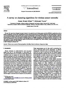
In our simulation, networks are generated randomly in the Euclidean plane where the number of nodes is 100. The sink node s is deployed at the top left corner and the others are randomly deployed on an area of size 400 × 400. Similar to (Chen et al., 2009), the initial graphs are built by assigning a uniform power level that is minimally required for the network to be connected. While the original SDA algorithm (Chen et al., 2009) takes into account only the conflict-free model with α = 1, we consider the cases: α = 1, 2 and 3. In order to compare the performances of the SDA, MDAB, and Cell Coloring algorithms, they are run on the same graphs. We generated 100 different networks, and averaged the lengths of the schedules produced by the algorithms over the networks generated. Figure 2.4 shows schedules computed by SDA, MDAB, and Cell Coloring where α = 1 and nodes have a uniform power level. Table 2.1 shows that MDAB performs much better than SDA (Chen et al., 2009) and Cell Coloring on average. It can also be observed that as α becomes larger (i.e., the interference range is wider), MDAB’s performance is increasingly better than SDA’s and Cell Coloring’s.
25
(a)
(b)
(c)
(d)
Figure 2.4. Schedules computed by SDA, MDAB, and Cell Coloring where α = 1 and nodes have a uniform power level. (a) Unit Disk Graph (b) SDA schedule (c) MDAB schedule (d) Cell Coloring schedule. Black nodes represent dominators, and gray nodes represent connectors. Since the Cell Coloring algorithm colors the nodes level by level on the data aggregation tree, it gives a larger latency than SDA and MDAB. Table 2.1. Average length of schedules computed by SDA, MDAB, and Cell Coloring algorithms Interference Factor 1 2 3
SDA 23.22 41.04 58.27
MDAB 21.13 33.73 47.85
Cell Coloring 68.30 76.76 86.76
26 2.8
Conclusion
In this chapter, we have studied the MDAS problem on the collision-free and interference-free networks. We have shown that there is no approximation algorithm having an approximation ratio better than Ω (log n) for the MDAS problem in the metric model under the assumption that each node can have various transmission power levels (non-uniform power model). For the non-uniform power model, we introduced a heuristic called the MDAB algorithm that yields a significant improvement over SDA (Chen et al., 2009) although both have similar worst case upper bounds. For the uniform power model, we proposed a nearly constant factor approximation algorithm called Cell Coloring whose latency is bounded by O(∆ + R), where ∆ is the maximum node degree of the network and R is the network radius. To our knowledge, the complexity of MDAS in the geometric model remains an interesting open problem.
CHAPTER 3 MINIMUM LATENCY AGGREGATION SCHEDULING PROBLEM IN INTERFERENCE-AWARE 3-DIMENSIONAL WSNS 3.1
Abstract
In this chapter, we study the Minimum Latency Aggregation Scheduling (MLAS) problem in Wireless Sensor Networks (WSNs) adopting the two interference models: the graph model and the more realistic physical interference model known as Signal-to-Interference-NoiseRatio (SINR). The main issue of the MLAS problem is to compute schedules with the minimum number of timeslots, that is, to compute the minimum latency schedules, such that data can be aggregated without any collision or interference. While existing works studied the problem in 2-dimensional (2D) WSNs only, we investigate the problem in the more general 3-dimensional (3D) WSNs, and introduce two approximation algorithms with O(1)-approximation ratios that yield schedules whose latency is bounded by O(∆ + R), where ∆ is the maximum node degree and R is the network radius. To the best known of our knowledge, our results are the first results of the MLAS problem in 3D WSNs.
3.2
Introduction
A Wireless Sensor Network (WSN) consists of a number of sensor nodes which monitor nearby environmental conditions and gather data periodically. The gathered data is forwarded to a destination called the sink node. This type of application is commonly known as data aggregation in the literature, and it is one of the most crucial applications of WSNs. Although recent advances in WSNs have led to the development of sensor nodes, the small-sized sensors still have limited energy resources. Therefore, researchers have focused on 27
28 the issue of prolonging the network lifetime by reducing energy consumption which is caused by the unnecessary retransmission using sensors’ limited power. An interesting approach is to assign timeslots to sensor nodes to obtain a good schedule by which data can be aggregated without any collision or interference. Since the data collection occurs periodically, reducing the latency of the schedule, that is, constructing schedules with a minimum number of timeslots, has been a fundamental issue. In the literature, the problem of constructing minimum latency data aggregation schedules, namely the Minimum Latency Aggregation Scheduling problem, has been widely investigated by several researchers in two interference models: the graph model and the physical interference model. In the collision-free graph model, (Chen et al., 2005) proved the NPhardness of the problem, and showed the (∆ − 1)-approximation algorithm. Later, (Huang et al., 2007) introduced the first constant factor approximation algorithm whose latency is bounded by 23R + ∆ − 18 which was improved by (Xu et al., 2009) and (Xu et al., 2011) to 16R + ∆ − 14. In (Wan et al., 2009), Wan et al. proposed three approximation algorithms � � R √ whose latency is bounded by 15R + ∆ − 4, 2R + O(log R) + ∆ and 1 + O( log ) R + ∆, 3 R respectively. While these works considered only collision, some researchers have studied the problem taking into consideration interference as well in the collision-interference-free graph model. (Wan et al., 2009) and (An et al., 2011) proposed constant factor approximation algorithms whose latency is bounded by O(∆ + R), and (An et al., 2011) also proved an Ω(log n) approximation lower bound in the metric model. Recently, (Lam et al., 2013) introduced a constant factor approximation algorithm whose latency is bounded by O(R+log n) assuming that multiple power levels are present, and the maximum power level is bounded, while (Wan et al., 2009; An et al., 2011) assumed the uniform power model. Recently, several researchers have started investigating data aggregation scheduling in the more realistic physical interference model known as Signal-to-Interference-Noise-Ratio
29 (SINR). Unlike the graph model, the SINR model captures real world phenomena adequately by considering the cumulative interference caused by all the other concurrently transmitting nodes. The first investigation of the Minimum Latency Aggregation Scheduling problem in the SINR model was done by Li et al. (Li et al., 2009). (Li et al., 2009) introduced a constant factor approximation algorithm whose latency is bounded by O(∆ + R) under the uniform power model. (An et al., 2012b) extended it to the dual power model, and introduced two constant factor approximation algorithms whose latency is bounded by O(∆ + R). (An et al., 2012b) also showed not only an Ω(log n) approximation lower bound in the metric SINR model, but also its NP-hardness in the geometric SINR model. (Li et al., 2010) proposed an algorithm that yields O(log3 n)-latency which was improved by (Halld´orsson and Mitra, 2012) to O(log n). Recently, (Lam et al., 2013) introduced a constant factor approximation algorithm whose latency is bounded by O(R + log n). Note that (Li et al., 2010) and (Halld´orsson and Mitra, 2012) assumed the unlimited power model and (Lam et al., 2013) assumed that multiple power levels are present, and the maximum power level is bounded. Following shows a summary of the works concerning the data aggregation problem in 2-dimensional WSNs. • Collision-Free Model – Uniform Power Model: (Chen et al., 2005; Huang et al., 2007; Xu et al., 2009, 2011; Wan et al., 2009; Yu et al., 2009) – Non-uniform Power Model: (Lam et al., 2013) • Collision-Interference-Free Model – Uniform Power Model: (Wan et al., 2009; An et al., 2011) – Non-uniform Power Model: (Lam et al., 2013)
30 • SINR Model – Uniform Power Model: (Li et al., 2009, 2010; Wan et al., 2009) – Non-uniform Power Model: (Lam et al., 2013; An et al., 2012b; Halld´orsson and Mitra, 2012) While these studies have been concerned with data aggregation, some other researchers have focused on related applications such as broadcast and gossiping. The broadcast problem is to distribute a unique message from a source (sink) node to all the other nodes, whereas the gossiping problem, which is also known as all-to-all broadcast, is to distribute the message of each node to all the other nodes in the network. For the problem of broadcast, NP-hardness was proved by (Gandhi et al., 2003) which holds for the collision-free graph model, but not for the other models. For the gossiping problem, (An et al., 2010b) proved its NP-hardness which holds for the SINR model under assumption that a node can combine messages and there is no limit on the length of the combined message. Following shows a summary of works on this topic. • Collision-Free Model – Broadcast: (Gandhi et al., 2003; Huang et al., 2007; Gandhi et al., 2009; Tiwari et al., 2009) – Gossiping: (Bar-yehuda et al., 1993; Christersson et al., 2002; Manne and Xin, 2006; Cicalese et al., 2006; Huang et al., 2008; Gandhi et al., 2009, 2003; An et al., 2010b; Krzywdzinski, 2010) • Collision-Interference-Free Model – Broadcast: (An et al., 2010b; Tiwari et al., 2009; Chen et al., 2007; Huang et al., 2008; Calinescu and Tongngam, 2011)
31 – Gossiping: (An et al., 2010b)
• SINR Model
– Broadcast: (An et al., 2010b; Huang et al., 2008) – Gossiping: (Wan et al., 2009; An et al., 2010b; Xin, 2010)
Among these works that studied the problems in 2-dimensional WSNs, (Tiwari et al., 2009) was the only one that has investigated the broadcast problem in both 2- and 3dimensional WSNs. In 3-dimensional (3D) WSNs adopting the graph model, (Tiwari et al., 2009) introduced a constant factor approximation algorithm where the 3D space is partitioned into several truncated octahedrons. In this chapter, we continue the study of the Minimum Latency Aggregation Scheduling problem in 3D WSNs adopting both the graph model and geometric SINR model. While existing works studied the problem in 2-dimensional (2D) WSNs only, we investigate the problem in the more general 3-dimensional (3D) WSNs, and introduce two constant factor approximation algorithms that yield schedules whose latency is bounded by O(∆ + R). Our approximation algorithms for the problem are the first results, to the best of our knowledge, for 3D WSNs adopting both interference models. This chapter is organized as follows. Section 3.3 describes our network models and defines the Minimum Latency Aggregation Scheduling (MLAS) problem. In Section 3.4, we show our 3D-space-filling and labeling techniques. Section 3.5 introduces two constant factor approximation algorithms for the MLAS problem, and we analyze them in Section 3.6. Finally, Section 3.7 contains some concluding remarks.
32 3.3
Preliminaries
3.3.1
3D Network Models
In this chapter, a wireless sensor network (WSN) consists of a set V of sensor nodes deployed in a 3-dimensional (3D) space, and each node u ∈ V is assigned a transmission power level p(u). Accordingly, a directed edge (u, v) exists from node u to node v, if v resides in the transmission ball with radius p(u) of u, i.e., d(u, v) ≤ p(u), where d(u, v) denotes the Euclidian distance between u and v.
Graph Model u In the graph model, let Bp(u) = {v | v ∈ V, d(u, v) ≤ p(u)} denote the set of all nodes
that can be reached by u with the power level p(u). If two nodes u and v reside in the u v , then u and v can communicate. and v ∈ Bp(u) transmission ball of each other, i.e., u ∈ Bp(v)
However, we also need to consider the collision or interference. Given a power level p(u) of u, the interference ball of u is defined as a ball with radius ρ · p(u), where ρ ≥ 1 is the u = {v | v ∈ V, d(u, v) ≤ ρ · p(u)} interference factor. (See Figure 3.1.) Given ρ ≥ 1, let Ip(u)
denote the set of all nodes in the interference ball of u. Then, collision (or conflict) is said to occur at a receiver node w if there exist other concurrently sending nodes u and v such u v that w ∈ Bp(u) ∩ Ip(v) , where ρ = 1. On the other hand, interference is said to occur at w u v if there exist other concurrently sending nodes u and v such that w ∈ Bp(u) ∩ Ip(v) , where
ρ > 1. In the literature, the graph model concerning only collision (i.e., when ρ = 1) is called the collision-free graph model, whereas the graph model concerning both collision and interference (i.e., when ρ ≥ 1) is called the collision-interference-free graph model. In the graph model, the communication graph can be modeled as a bidirectional ball graph G(V, E), where E = {(u, v) | u, v ∈ V, d(u, v) ≤ p(u) and d(v, u) ≤ p(v)}.
33
Figure 3.1. Transmission ball and interference ball of u SINR Model In the physical interference model (SINR) (Gupta and Kumar, 2000), if a node u transmits with its power level p(u), then the received power at a receiver v is p(u) · d(u, v)−α , where α ∈ [2, 6] is the path loss exponent. In order that the receiver v can receive the data transmitted by the sender u, the ratio of the received power at v to the interference caused by all the other concurrently transmitting nodes and background noise must be beyond an SINR threshold β ≥ 1. Formally, node v can successfully receive data via the communication edge (u, v) only if SIN R(u,v) =
p(u) d(u,v)α
N+
p(w) w∈X−{u,v} d(w,v)α
P
≥β
(3.1)
where N > 0 is the background noise, and X is the set of other concurrently transmitting 1
nodes. Observing that u can send its data to the nodes within the distance ( p(u) ) α , the Nβ network can be modeled as a directed ball graph G(V, E), where E = {(u → v)|u, v ∈ 1
) α }. V, d(u, v) ≤ ( p(u) Nβ Note that in the literature, a communication graph is called a ball graph (BG) if all nodes are assigned various power levels, and if all nodes are assigned the same power level, it is called a unit ball graph (UBG).
34 3.3.2
Problem Definition
The Minimum Latency Aggregation Scheduling (MLAS) problem is defined as follows. Considering a set of nodes in a 3D space, we assign these nodes a number of timeslots such that nodes scheduled to send data at the same timeslot can send data to its receivers simultaneously without any collision or interference. A schedule is defined as a sequence of such timeslots. Formally, at each timeslot t, we have an assignment vector πt = h(st1 , p(st1 )), · · · , (stm , p(stm ))i in which sti is assigned to send data with its power level p(sti ), 1 ≤ i ≤ m, and • (Graph Model) neither collision nor interference occurs at any receiver r, or • (SINR Model) the SINR threshold inequality is satisfied for all receivers r, where (sti , r) is an edge in the communication graph G(V, E). A schedule is a sequence of assignment vectors Π = (π1 , π2 , · · · , πM ), where M is the length of the schedule which is also called its latency. A schedule Π is successful if all data of each node v ∈ V is aggregated to a sink node s ∈ V . Input. A set V of nodes in a 3-dimensional (3D) space, a sink node s ∈ V . Output. A successful minimum latency schedule. 3.3.3
NP-Hardness of the MLAS Problem in 3D WSNs
Note that (Chen et al., 2005), (An et al., 2011) and (An et al., 2012b) showed the NP-hardness of the MLAS problem in the 2-dimensional (2D) collision-free graph model, collision-interferencefree graph model, and SINR model, respectively. Observing that a 2D WSN is a special case of 3D WSNs, the MLAS problem in 3D WSNs is also NP-hard. 3.4
3-Dimensional Space Filling
In this section, we introduce our 3-dimensional (3D) space-filling technique. It has been known that there are only five space-filling convex polyhedra: triangle prism, cube, hexagonal
35 prism, truncated octahedron, and gyrobifastigium. In this chapter, we fill the 3D space with the cube, which is the only platonic solid, and the hexagonal prism. 3.4.1
Space Filling with Cubes
We partition the 3D space containing the network into cubes whose side length a is
√r , 3
and
space diagonal is r. (See Figure 3.2(a).) Each cube is labeled with the label CL(x, y, z) if (x, y, z) is its vertex with the smallest x−, y− and z− coordinates.
(a) Cube
(b) Hexagonal Prism
Figure 3.2. Space-filling convex polyhedra
3.4.2
Space Filling with Hexagonal Prisms
The 3D space containing the network is tessellated with hexagonal prisms whose side length a is
√r , 5
and space diagonal is r. (See Figure 3.2(b).) The hexagonal prisms are labeled using
(9k 3 − 3k 2 )-labeling, where k is a positive integer. Figure 3.3(a) shows a (3 × 2)-labeling when k = 1. The (3 × 2)-labeling consists of 2 layers each of which consists of 3 hexagonal prisms. Figure 3.3(b) shows an example of filling a 3D network space using (3 × 2)-labeling. In this (3 × 2)-labeling, we can observe that the distance between two hexagonal prisms with the same label is
√r . 3
Here, the distance between any two hexagonal prisms, denoted by hexi
and hexj , respectively, is defined as the distance between two closest vertices p in hexi , and p0 in hexj . Next, Figure 3.4(a) shows (12 × 5)-labeling when k = 2, and it consists of 5 layers each of which consists of 12 hexagonal prisms. Figure 3.4(b) shows an example of hexagonalprism tessellation on a 3D network using (12 × 5)-labeling. In this (12 × 5)-labeling, the
36 distance between two hexagonal prisms with the same label is 4 ·
√r . 3
When k = 3, we have
(27 × 8)-labeling that consists of 8 layers each of which consists of 27 hexagonal prisms. (See Figure 3.5.) When a 3D network is filled with the hexagonal prisms with (27 × 8)-labeling, the distance between the hexagonal prisms is 7 ·
√r . 3
(a)
(b)
Figure 3.3. (a) 6-labeling (k = 1) (b) Space-filling with 6-labeling
(a)
(b)
Figure 3.4. (a) 60-labeling (k = 2) (b) Space-filling with 60-labeling In general, we have a K = (3k 2 × (3k − 1))-labeling, and the distance between two hexagonal prisms with the same label is (3k − 2) ·
3.5
√r . 3
Constant Factor Approximation Algorithms
Cube-based Aggregation Scheduling Algorithm The first algorithm called the Cube-based Aggregation Scheduling (CBAS) algorithm starts by partitioning the network into cubes as described in Section 3.4.1, and a number of iterations
37
Figure 3.5. 216-labeling (k = 3) are performed to find a schedule based on T . Assigning timeslots is also based on the constant value C that guarantees that any two senders can send data to their receivers at the same time if they are C cubes apart from each other. Now, the constant C is set as follows in the two different interference models: • Graph model: C = dρ ·
√
3 + 3e 2
1
·4π • SINR model: C = d( N (δ−αP−1)(α−3) ) α−3 ·
√
1 3 Nβ α (P ) δ
+ 2e
Then, the CBAS algorithm can be used not only for the graph model, but also for SINR model where the constant C is defined accordingly. Algorithm 4 shows the details of the CBAS algorithm. It schedules the nodes in T starting with the dominatees so that they can send data without any collision or interference to their dominators (Steps 4 – 5 in Algorithm 4). While scheduling dominatees, the CBAS algorithm (Algorithm 4) uses Algorithm 5 as a subroutine to assign the same timeslots to the dominatees if they are C cubes away from each other. Note that while scheduling, we pick only one dominatee in each cube arbitrarily (Step 2 in Algorithm 5), and repeat the scheduling procedure (Algorithm 5) until all dominatees are scheduled.
38 Algorithm 4 Cube-based Aggregation Scheduling (CBAS) Input: A set V of nodes in a 3D space Output: Length of Schedule 1: Fill the space with cubes whose edge length is √r . 3 2: Construct a data aggregation tree T using the algorithm in (Huang et al., 2007) rooted at a center node c. 3: Set the first timeslot t ← 1 4: Sd ← the set of dominatees 5: t ← TA-C(Sd , t) 6: for i = R to 1 do 7: Sdi ← the set of dominators at level i in T 8: if Sdi 6= ∅ then t ← TA-C(Sdi , t) 9: Sci ← the set of connectors at level i in T 10: if Sci 6= ∅ then t ← TA-C(Sci , t) 11: end for 12: Send the aggregated data from the center node c to the sink node s via a shortest path f. 13: return (t − 1)+ length of f Algorithm 5 TimeSlot Assignment (TA-C) Input: A set S of sender nodes and a starting timeslot t Output: Timeslot t 1: while S 6= ∅ do 2: Pick one node vs ∈ S in each cube. Let S 0 ⊆ S be the set of such nodes. 3: for t1 = 0, ..., C, t2 = 0, ..., C, t3 = 0, ..., C do 4: S 00 ← ∅, S 00 ← {vs |vs ∈ S 0 with CL(x, y, z) such that t1 = x mod (C + 1), t2 = y mod (C + 1) and t3 = z mod (C + 1)} 5: if S 00 6= ∅ then 6: for each vs ∈ S 00 do 7: T S(vs ) ← t 8: end for 9: t ← t + 1, S ← S − S 00 , S 0 ← S 0 − S 00 10: end if 11: end for 12: end while 13: return t After all dominatees are scheduled, several iterations are performed (Steps 6 – 11 in Algorithm 4) to schedule the remaining dominators and connectors level by level until all of them are scheduled, as follows. At each iteration for level i of T , if there exist dominators
39 that have just received data from their lower level dominatees or connectors at level i+1, then the dominators are scheduled to send the aggregated data to their upper level connectors at level i − 1. Otherwise, if there exist connectors that have just received data from their lower level dominators at level i + 1, then the connectors are scheduled to send the aggregated data to their upper level dominators at level i − 1. While scheduling, the CBAS algorithm (Algorithm 4) also uses Algorithm 5 as a subroutine to assign the same timeslots to them if they are C cubes away from each other. Notice that there exists only one dominator in a cube, whereas there may exist several connectors in a cube. Therefore while scheduling connectors, at each level i, we pick only one connector in each cube arbitrarily (Step 2 in Algorithm 5), and repeat the scheduling procedure (Algorithm 5) until all connectors at level i are scheduled. Once all data is aggregated to the center node c, c sends the aggregated data to the sink node s via a shortest path (Step 12 in Algorithm 4).
Hexagonal-Prim-based Aggregation Scheduling The second algorithm called Hexagonal-Prim-based Aggregation Scheduling (HPBAS) starts by partitioning a network into hexagonal prisms which are labeled using K = (9k 3 − 3k 2 )labeling as described in Section 3.4.2, and a number of iterations are performed to find a schedule based on T obtained as the CBAS algorithm. Assigning timeslots is also based on the constant value K that guarantees that any two senders can send data to their receivers at the same time if they are located in the hexagonal prisms with the same label according to the K-labeling. Let us set the constant K as follows in the two different interference models: √
• Graph model: K = 9k 3 − 3k 2 , where k = d • SINR model: K = 9k 3 − 3k 2 , where k = d 13 {
5(ρ+2)+2 e 3
√
5 δ
1
2
1
·4π · ( NPβ ) α · ( N (δ−1P−1)(α−3) ) α−3 +
√
5 + 2}e
40 The HPBAS algorithm can be used not only for the graph model, but also for the SINR model where the constant K is defined accordingly. Algorithm 6 shows the details of the HPBAS algorithm. Similar to CBAS, the HPBAS algorithm first schedules the dominatees (Steps 4 – 5 in Algorithm 6), and then several iterations are performed to schedule the remaining dominators and connectors (Steps 6 – 11 in Algorithm 6). While scheduling, HPBAS uses Algorithm 7 as a subroutine to assign the same timeslots to node which are located in the hexagonal prisms with the same label. As the final step, the aggregated data at the center node c is sent to the sink node s via a shortest path (Step 12 in Algorithm 6). Algorithm 6 Hexagonal-Prism-based Scheduling Input: A set V of nodes in a 3D space Output: Length of Schedule 1: Fill the space with hexagonal prims whose side length is √r , and label the prisms using 5 K-labeling. 2: Construct an aggregation tree T using an algorithm in (Huang et al., 2007) rooted at a center node c. 3: Set the first timeslot t ← 1 4: Sd ← the set of dominatees of V . 5: t ← TA-X(Sd , t) 6: for i = R to 1 do 7: Sdi ← the set of dominators at level i in T 8: if Sdi 6= ∅ then t ← TA-X(Sdi , t) 9: Sci ← the set of connectors at level i in T 10: if Sci 6= ∅ then t ← TA-X(Sci , t) 11: end for 12: Send the aggregated data from the center node c to the sink node s via a shortest path f. 13: return (t − 1)+ length of f
3.6
Analysis
In this section, we analyze the Cube-Based Aggregation Scheduling (CBAS) and HexagonalPrim-Based Aggregation Scheduling (HPBAS) algorithms (Algorithms 4 and 6).
41 Algorithm 7 TimeSlot Assignment (TA-X) Input: A set S of sender nodes and a starting timeslot t Output: Timeslot t 1: while S 6= ∅ do 2: Pick one node vs ∈ S in each cube. Let S 0 ⊆ S be the set of such nodes. 3: for i = 1 to K do 4: S 00 ← ∅, S 00 ← {vs |vs ∈ S 0 with HL(vs ) = i} 5: if S 00 6= ∅ then 6: for each vs ∈ S 00 do 7: T S(vs ) ← t 8: end for 9: t ← t + 1, S ← S − S 00 , S 0 ← S 0 − S 00 10: end if 11: end for 12: end while 13: return t 3.6.1
Analysis of CBAS Algorithm
First, we analyze the CBAS algorithm, and bound the latency of the schedule produced by it. We first prove that any two senders can send data at the same time without any collision and interference if they are C cubes apart. √ Lemma 3.6.1 (Graph Model). Let C = dρ · 3 + 3e, where ρ ≥ 1 is the interference factor. Then any two sender nodes that are at least C cubes apart from each other can concurrently send data without any collision and interference. Proof. Consider a sender node vi trying to send data to its receiver vj , and the farthest sender node vk that interferes with vj . Then, d(vk , vj ) ≤ ρ · r. Next, letting z denote the number of cubes between vj and vk , we bound z as follows. Consider the straight line between vj and vk . Then, as √r3 · z ≤ d(vk , vj ), we have z ≤ √ √ √ d(vk , vj ) · r3 which implies that z ≤ ρ · 3. Therefore, there are at most dρ · 3e cubes √ between vj and vk , and any other sender must be at least dρ · 3 + 1e cubes apart from the node vj not to cause interference. Now, observing that the number of cubes between vi and vj √ is at most 1, and considering the cube in which vj is located, we can set C = dρ · 3 + 3e.
42 Lemma 3.6.2 (SINR Model). For SINR threshold β ≥ 1, path loss exponent α > 3, background noise N > 0, and some constant δ ∈ (0, 1), let 2
1
·4π ) α−3 · C = d( N (δ−αP−1)(α−3)
√ 1 3 · (δ( NPβ ) α )−1 + 2e
Then any two sender nodes that are at least C cubes away from each other can send data at the same time. Proof. Consider a sender node vi trying to send data to its farthest possible receiver vj , i.e., 1
d(vi , vj ) = δ( NPβ ) α . In order that the receiver vj receives data from the sender vi without interference, for all other concurrently sending nodes, the following must be satisfied: �−α � 1 P δ( NPβ ) α P ≥β 0 −α N + v0 ∈{v / i ,vj } P · d(vi , vj ) i
which implies P
P
1 vi0 ∈{v / i ,vj } d(vi0 ,vj )α
N (δ −α − 1)
≤
P
R 2π R 2π R ∞ 0
y2 dy x yα N (δ −α − 1) 0
dθ dϕ
(3.2)
R∞ P · 4π 2 x y 2−α dy = N (δ −α − 1) P · 4π 2 · x3−α ≤1 = N (δ −α − 1)(α − 3)
(3.3) (3.4)
where x is the shortest distance between vj and one of the other concurrently sending nodes. 2
1
2
1
·4π ·4π From inequality (3.4), we get x ≥ ( N (δ−αP−1)(α−3) ) α−3 . Thus X := ( N (δ−αP−1)(α−3) ) α−3 is a
lower bound for x. Next, let us bound the number of cubes between vj and a closest concurrently sending node to vj , say vi0 . Let z be the number of cubes between vi0 and vj . We bound z as follows. Consider the straight line between vi0 and vj , and the cubes lying on the line. We have √ 1 1 X ≤ z · √13 · δ( NPβ ) α which implies X · 3 · (δ( NPβ ) α )−1 ≤ z. Therefore, vj and vi0 should be √ 1 at least Z := dX · 3 · (δ( NPβ ) α )−1 e cubes apart. Now, observing that the number of cubes between vi and vj is at most 1, and considering the cube in which vj is located, we can set √ 1 1 ·4π 2 C = d( N (δ−αP−1)(α−3) ) α−3 · 3 · (δ( NPβ ) α )−1 + 2e.
43
Figure 3.6. The inscribed ball that touches each face of the cube. Lemma 3.6.3. The number of connectors in a cube is at most 73 − 1. Proof. Consider a dominator v in a cube, denoted by cube(v), and its connectors. As the connectors connect dominators which are 2-hops away from v in the CDS, the number of connectors in one cube cannot exceed the number of dominators that are at most 2 hops away from v. Thus, it is sufficient to bound the number of such dominators. Consider a ball, whose radius is 2r, that is totally contained within a cube, denoted by cube0 , with the side length 4r (See Figure 3.6). Then, the number of 2-hop away dominators cannot exceed the number of cubes whose side length is √r3 within cube0 . As there exist at √ √ most d4 3e3 cubes whose side length is √r3 within cube0 , there are at most d4 3e3 dominators in cube0 . This implies that there exist at most 73 − 1 connectors for v, and therefore at most 73 − 1 connectors in a cube.
Lemma 3.6.4 (Lower Bound, Graph Model). (Xu et al., 2011) In order to produce a successful schedule, any data aggregation scheduling algorithm requires • ≥ max{∆, log R} timeslots, for ρ = 1, • ≥ max{ ∆ , R} timeslots, where φ = φ • ≥ max{∆, R} timeslots, for ρ ≥ 3.
2π , barcsin ρ−1 c 2ρ
for 1 < ρ < 3, and
44 Lemma 3.6.5 (SINR Model). (Li et al., 2009) For any node, at most ω =
rα β
−1 neighboring
1
nodes can send data at the same time, where r = δ( NPβ ) α . Corollary 3.6.1 (Lower Bound, SINR Model). In order to produce a successful schedule, any data aggregation scheduling algorithm requires ≥ max{ ∆ , R} timeslots. ω Theorem 3.6.1. The CBAS algorithm produces a successful schedule whose latency is bounded by O(∆ + R), and it is therefore a constant-factor approximation algorithm. Proof. First, consider the Steps 4 – 5 in Algorithm 4 that schedules dominatees. In a cube, there exist at most ∆ dominatees sharing one dominator v. Thus, gathering data from all the dominatees to the corresponding dominators takes at most ∆ · (C + 1)2 timeslots. Next, consider Steps 6 – 11 in Algorithm 4 that schedule the remaining dominators and connectors. For each iteration that schedules nodes at level i, we consider the following cases: 1. Assigning timeslots to dominators at level i to send data to their connectors at level i − 1: In this case, there exists at most 1 dominator in a cube, and therefore gathering data from all the dominators at level i to the corresponding connectors at level i − 1 takes at most (C + 1)2 timeslots. 2. Assigning timeslots to connectors at level i to send data to their dominators at level i − 1: In this case, there exist at most 73 − 1 connectors in a cube (Lemma 3.6.3), and therefore gathering data from all the connectors at level i to the corresponding dominators at level i − 1 takes at most (73 − 1)(C + 1)2 timeslots. As Steps 6 – 11 repeat at most R times, it takes at most 73 (C + 1)2 · R timeslots. Finally, as Step 12 in Algorithm 4 takes at most R timeslots, the latency of CBAS is bounded by (C + 1)2 · ∆ + 73 (C + 1)2 · R = O(∆ + R). Thus, it is a constant factor approximation in both the graph model and the SINR model by Lemma 3.6.4 and Corollary 3.6.1.
45 3.6.2
Analysis of HPBAS Algorithm
We now analyze the HPBAS algorithm, and bound the latency of the schedule produced by it. We first prove that any two senders can send data at the same time without any collision and interference if they are located in the hexagonal prisms with the same label according to the K-labeling. Lemma 3.6.6 (Graph Model). Let k = d
√ 5(ρ+2)+2 e, 3
where ρ ≥ 1 is the interference factor.
Then any two sender nodes which are located in the hexagonal-prisms with the same label according to the K-labeling can send data at the same time. Proof. Consider a sender node vi sending its data to its farthest possible receiver vj , i.e., d(vi , vj ) = r. The proof of Lemma 3.6.1 showed that the farthest distance between vj and the other sender node that interferes with vj , say vk , is at most ρ · r. As the maximum distance between any two nodes is r, if any two senders are ρ · r + 2r distance apart from each other, then they can send data at the same time. Next, the distance between two hexagonal prisms with the same label is √
K = (9k 3 − k 2 )-labeling. Letting
√r (3k 5
− 2) ≥ ρ · r + 2r, we can set k = d
√r (3k 5
− 2) in
5(ρ+2)+2 e. 3
Lemma 3.6.7 (SINR Model). For SINR threshold β ≥ 1, path loss exponent α > 3, background noise N > 0, and some constant δ ∈ (0, 1), let k = d 31 {
√
5 δ
1
2
1
·4π · ( NPβ ) α · ( N (δ−1P−1)(α−3) ) α−3 +
√
5 + 2}e
Then any two sender nodes which are located in the hexagonal-prisms with the same label according to the K-labeling can send data at the same time. Proof. Consider a sender node vi sending its data to its farthest possible receiver vj , i.e., 1
d(vi , vj ) = r = δ( NPβ ) α . The proof of Lemma 3.6.2 showed that the shortest distance between 2
1
·4π vj and the other concurrently sending node is at least ( N (δ−1P−1)(α−3) ) α−3 . Since the maximum
46 1
distance is δ( NPβ ) α , any two sender nodes can send data at the same time if they are at least 2
1
1
·4π ) α−3 + δ( NPβ ) α apart from each other. of distance D := ( N (δ−1P−1)(α−3) √r (3k − 2) 5 √ 1 d 13 { δ5 · ( NPβ ) α ·
Next, the shortest distance between two hexagons with the same label is in K = (9k 3 − k 2 )-labeling. Letting √ 1 ·4π 2 ) α−3 + 5 + 2}e. ( N (δ−1P−1)(α−3)
√r (3k 5
− 2) ≥ D, we can set k =
Lemma 3.6.8. The number of connectors in a hexagonal prism is at most 73 − 1. Proof. The proof is similar to the proof of Lemma 3.6.3, and is omitted. Theorem 3.6.2. The HPBAS algorithm produces a successful schedule whose latency is bounded by O(∆ + R), and it is therefore a constant-factor approximation algorithm. Proof. Using an argument similar to the one the proof of Theorem 3.6.1, the latency of the schedules produced by the HPBCA algorithm (Algorithm 6) can be bounded by K · ∆ + 73 · K · R = O(∆ + R). Thus, it is a constant factor approximation in both the graph model and the SINR model by Lemma 3.6.4 and Corollary 3.6.1.
3.7
Conclusion
In this chapter, we studied the Minimum Latency Aggregation Scheduling (MLAS) problem adopting the two interference models: the graph model and the more realistic physical interference model known as Signal-to-Interference-Noise-Ratio (SINR). While existing works studied the problem in 2-dimensional (2D) WSNs only, we investigated the problem in the more general 3-dimensional (3D) WSNs, and introduced two approximation algorithms with O(1)-approximation ratios that yield schedules whose latency is bounded by O(∆ + R), where ∆ is the maximum node degree and R is the network radius. As to future work, we plan to study the other related problems such as broadcast as well as gossiping in 3D WSNs adopting both interference models.
CHAPTER 4 MINIMUM LATENCY GOSSIPING IN WIRELESS SENSOR NETWORKS 4.1
Abstract
Gossiping is one of the most crucial applications in Wireless Sensor Networks (WSNs) which has been the focus of many researchers. A main issue of gossiping is how to assign timeslots to nodes for interference-free data transmission. There are three models concerning gossiping in WSNs: unit-sized, bounded-sized, or unbounded-sized messages. For these models, the problem of constructing minimum latency gossiping schedules has been widely studied in the literature although most of the existing studies are based on the graph model. In this chapter, we study the Minimum Latency Gossiping (MLG) problem with unboundedsized messages in the graph model as well as the more realistic physical interference model known as Signal-to-Interference-Noise-Ratio (SINR) where there exist relatively few works (Wan et al., 2009) on the three gossiping models. In the SINR model, we prove the NPhardness of the MLG problem with unbounded-sized messages. In both the graph model and SINR model, we propose a constant factor approximation algorithm that yields schedules whose latency is bounded by O(∆ + R), where ∆ is the maximum node degree of a network and R is its radius. We also study the performance of the algorithm through simulation.
4.2
Introduction
The gossiping problem has been the focus of many researchers as it is one of the crucial applications in Wireless Sensor Networks (WSNs) along with the broadcast problem. In a WSN that consists of a number of sensor nodes, the gossiping problem, which is also known as all-to-all broadcast, is to distribute the message of each node to all the other nodes 47
48 in the network, whereas the broadcast problem is to distribute a unique message from a source node to all the other nodes. As the small-sized sensors have limited energy resources, researchers have focused on reducing energy consumption while distributing data in a network so that the network life time is extended. An interesting approach is to assign timeslots to nodes to obtain a good (short) schedule thereby avoiding unnecessary transmissions. As data distribution may occur periodically, reducing the latency of the schedule, that is, constructing schedules with a minimum number of timeslots, has been a fundamental issue in such applications. In the literature on the gossiping problem, there are three models: unit-sized, boundedsized, or unbounded-sized messages. In the unit-sized-message model, a node can send a single unit-sized message, and therefore combining messages is not allowed. In the boundedsized-message model, a node can combine messages that have been received so far (up to some limit), whereas in the unbounded-sized-message model, there is no limit on the length of the combined message. The gossiping problem in the graph model has been investigated by many researchers over the last several years. In the collision-free graph model, for the unit-sized-message model, (Gandhi et al., 2003) introduced a 1974-approximation algorithm, and (Manne and Xin, 2006) proposed an optimal randomized schedule with a latency bounded by O(n log n), where n is the number of sensor nodes in the network. Later, (Huang et al., 2008) introduced a 27-approximation algorithm which produces gossiping schedules with a latency bounded by 27(n+R −1), where R is the network radius. In (Gandhi et al., 2008), two approximation algorithms with constant factors of 20 and 34 have been studied. For the bounded-sizedmessage model, (Bar-yehuda et al., 1993) studied the gossiping problem where messages can be combined into a single message whose size is bounded by log n, and (Christersson et al., 2002) gave an improvement over (Bar-yehuda et al., 1993). For the unbounded-sized-message model, (Cicalese et al., 2006) showed that their algorithm produces gossiping schedules
49 with O(g +
ν log n ) log ν−log log n
timeslots, where ν = Ω(log n) and g is the network diameter, and
(Krzywdzinski, 2010) introduced a constant factor approximation algorithm whose latency is bounded by 7∆ + 258R. Although there have been many studies in the collision-free graph model for the gossiping problem, surprisingly there exists no study in the collisioninterference-free graph model, to the best of our knowledge. The graph model which has been used in many studies, however, is not an adequate model since cumulative interference caused by all the other concurrently transmitting nodes is ignored. Thus, researchers have started investigating problems in WSNs in the more realistic physical interference model which is known as the Signal-to-Interference-Noise-Ratio (SINR) model since its introduction by Gupta et al. in (Gupta and Kumar, 2000). For the SINR model, (Wan et al., 2009) introduced a constant factor approximation algorithm for the gossiping problem in the unit-sized-message model, and (Xin, 2010) proposed a O(log n)-approximation algorithm for the unbounded-sized-message model. However, (Xin, 2010) considered only the concurrently sending nodes within some pre-defined interference area from a receiver, and therefore, some interference caused by senders located far away is ignored. While these studies have been concerned with gossiping, some other researchers have focused on related applications such as data aggregation and broadcast. The following shows a summary of some related works. • Collision-Free Model
– Data Aggregation: (Chen et al., 2005; Huang et al., 2007; Wan et al., 2009; Xu et al., 2011) – Broadcast: (Gandhi et al., 2003; Huang et al., 2006, 2007; Gandhi et al., 2008)
50 • Collision-Interference-Free Model – Data Aggregation: (Wan et al., 2009; An et al., 2011) – Broadcast: (Chen et al., 2007; Huang et al., 2008; Calinescu and Tongngam, 2011) • SINR Model – Data Aggregation: (Li et al., 2009, 2010; Lam et al., 2011; Halld´orsson and Mitra, 2012; Hobbs et al., 2012) – Broadcast: (Huang et al., 2008) Although there have been several approximation algorithms for these related problems, there are surprisingly few studies regarding the complexity of the problems. For the problem of data aggregation, NP-hardness was proved for the collision-free model by (Chen et al., 2005), and (An et al., 2011) and (Lam et al., 2011) showed not only an Ω(log n) approximation lower bound for the problem, but also the NP-hardness in the collision-interference-free graph model and the geometric SINR model, respectively. For the broadcast problem, (Gandhi et al., 2003) proved its NP-hardness in the collision-free model. However, to the best of our knowledge, the NP-hardness of the broadcast problem in both the collision-interference-free and SINR models as well as that of the gossiping problem in all network models remain open. (Note that the existing NP-hardness of the broadcast problem in (Gandhi et al., 2003) holds for the collision-free graph model, but not for the other models.) In this chapter, we continue the study of the gossiping problem with unbounded-sized messages in the graph model and the geometric SINR model. Extending the proof in (Lam et al., 2011), we show that this problem is NP-hard in the geometric SINR model. Additionally, for the uniform power model, we introduce a constant factor approximation algorithm yielding schedules whose latency is bounded by O(∆ + R) in both the graph model and the geometric SINR model. Our algorithm gives an improved approximation ratio of 224 over
51 the existing ratio of 285 given by (Krzywdzinski, 2010) in the collision-free graph model. In the collision-interference-free graph model and the SINR model, our approximation algorithm is the first one to the best of our knowledge. Moreover, regarding broadcast, the broadcast subroutine of our gossiping algorithm provides broadcast schedules with a better approximation ratio than existing ones given by (Chen et al., 2007; Huang et al., 2008) for the collision-interference-free model. This chapter is organized as follows. Section 4.3 describes our network models and defines the Minimum Latency Gossiping (MLG) problem with unbounded-sized messages. In Section 4.4, we show the NP-hardness of MLG in the geometric SINR model. Section 4.5 introduces a constant factor approximation algorithm for the MLG problem and shows some simulation results. Section 4.6 contains some concluding remarks.
4.3 4.3.1
Preliminaries Network Model
In this chapter, we model a wireless sensor network as (V, D, p), where V represents a set of n nodes, and D : V × V → R+ represents the distance function between nodes. Letting pmax : V → R+ be the maximum power level function, we define a power assignment function as p : V → R+ , p(u) ≤ pmax (u), u ∈ V .
Graph Model u In the graph model, given a transmission power level p(u) for each node u, let Rp(u) = {v|v ∈
V, D(u, v) ≤ p(u)} denote the set of all nodes that can be reached by u with the power level p(u). Two nodes u and v can communicate only if they are in the coverage area of v u each other, i.e., u ∈ Rp(v) and v ∈ Rp(u) . However, we also need to consider the collision
or interference that interferes with the communication. Given a power level p(u) of u, the
52 interference range of u is defined as ρ · p(u), where ρ ≥ 1 is the interference factor. Given u = {v|v ∈ V, D(u, v) ≤ ρ · p(u)} denote the set of all nodes in the interference ρ ≥ 1, let Fp(u)
range of u. Then, collision (or conflict) is said to occur at a receiver node w if there exist u v other concurrently sending nodes u and v such that w ∈ Rp(u) ∩ Fp(v) , where ρ = 1. On the
other hand, interference is said to occur at w if there exist other concurrently sending nodes u v u and v such that w ∈ Rp(u) ∩ Fp(v) , where ρ > 1.
In the literature, the graph model concerning only collision (i.e., when ρ = 1) is called the collision-free model, whereas the graph model concerning both collision and interference (i.e., when ρ ≥ 1) is called the collision-interference-free model. In the graph model, the communication graph can be modeled as a bidirectional graph G(V, E), where E = {(u, v)|u, v ∈ V, D(u, v) ≤ p(u) and D(v, u) ≤ p(v)}. SINR Model In the physical interference model (SINR) (Gupta and Kumar, 2000), if a node u transmits with its power level p(u), then the power received at another node v is p(u)·D(u, v)−α , where α, the path loss exponent, is commonly assumed to be in the interval [2, 6]. In order that node v can receive and decode data sent by u, the ratio of the received power at v to the interference caused by all the other concurrently transmitting nodes and background noise must be beyond an SINR threshold β ≥ 1. Formally, node v can receive data successfully via the link (u, v) only if SIN R(u, v) =
p(u) · D(u, v)−α ≥β N + Iv
(4.1)
p(w) · D(w, v)−α
(4.2)
where N > 0 is the background noise, and Iv =
X w∈{u,v},w∈X /
is the cumulative interference at v caused by nodes in X that is the set of other concurrently transmitting nodes. Observing that u can send its data to the nodes within the distance
53 1
( p(u) ) α , the communication graph can be modeled as a directed graph G(V, E), where E = NB 1
{(u → v)|u, v ∈ V, D(u, v) ≤ ( p(u) ) α }. NB 4.3.2
Problem Definition
In this chapter, we are concerned with gossiping in the unbounded-sized-message model, i.e., we assume that multiple messages can be combined as a single message, and there is no limit on the length of a message that one node can transmit. The Minimum Latency Gossiping (MLG) problem is defined as follows. A schedule is defined as a sequence of timeslots, at each of which, several nodes are scheduled to send its data to its receivers. Formally, at each timeslot t, we have an assignment vector πt = h(st1 , p(st1 )), . . . , (stk , p(stk ))i in which sti is assigned to send data with its power level p(sti ), 1 ≤ i ≤ k, and 1. (Graph Model) neither collision nor interference occurs at any receiver r, or 2. (SINR Model) the SINR threshold inequality is satisfied for all receivers r, where (sti , r) is an edge in the communication graph G(V, E), i.e., all the senders sti can transmit concurrently. A schedule is a sequence of assignment vectors Π = (π1 , π2 , . . . , πM ), where M is the length of the schedule which is also known as its latency. A schedule Π is successful if the message m(v) of each node v ∈ V is received by all the other nodes in the network. In a schedule, a node may be scheduled at several timeslots with different power levels. The MLG problem is defined as follows: Input. A set of nodes V , a distance function D which is defined as the Euclidean distance between nodes, a maximum power level function p. Output. A successful schedule of minimum length.
54 4.4
NP-Hardness
In this section, we prove the NP-hardness for the minimum latency gossiping (MLG) problem. The structure of this proof is similar to the one in the proof of the NP-hardness of the minimum latency aggregation problem in (Lam et al., 2011), which, as the proof of the NPhardness of scheduling with power control in geometric SINR (Vlker et al., 2009), is based on a construction in (Goussevskaia et al., 2007). We restate the construction in (Lam et al., 2011) for reader’s convenience and omit the details. In order to prove MLG’s NP-hardness, we construct a polynomial time reduction from the Partition problem which was proven NP-complete in (Karp, 1972). This decision problem is defined as follows. Given a finite set of distinct and positive integers, the objective is to determine if it is possible to divide this set into two subsets such that the sums of all integers in each subset are equal.
'$
'% &%(*
!
&
&% "
&$ #
%$&%()
Figure 4.1. The corresponding geometric MLG instance
Let IP be an instance of Partition which consists of a set S of n distinct and positive integers a1 , a2 , ...an . Without loss of generality, assume that a1 < a2 < ... < an . We construct in polynomial time an instance IM of the MLG problem as follows.
55 In the instance IM , we have 2n + 3 nodes including 2n nodes si and ri , 1 ≤ i ≤ n, 2 nodes sn+1 and sn+2 and a center node s. These nodes are deployed on the plane at the following positions. pos(s) = (0, 0) 1
α pos(sn+1 ) = (0, −( N β(A24P α β+24) ) ) 1
α pos(sn+2 ) = (−( N β(A24P α β+24) ) , 0)
and, for all 1 ≤ i ≤ n, 1
pos(si ) = (( biPN β ) α , 0) 1
pos(ri ) = (( biPN β ) α , d0 ) where P is the maximum power value to be defined below. Let σ = 1
( a1n ) α ), bi =
ai Aα 12σ
Pn
i=1
1
ai , A = (( an1−1 ) α −
1
σ and d0 = ( 12σN12P )α . β+nN β 2
With d(u, v) denoting the Euclidean distance between u and v, we define the maximum power level for the nodes as follow: pmax (si ) = pmax (sn+1 ) = pmax (sn+2 ) = P pmax (ri ) = N βd(ri , ri+1 )α , 1 ≤ i ≤ n, rn+1 ≡ s pmax (s) = N βd(s, s1 )α =
P b1
=
12P σ a1 Aα
>P
Fact 4.4.1. Let Ti = {sj |1 ≤ j ≤ n + 1 ∧ i 6= j}. It holds for all 1 ≤ i ≤ n that SIN R(si , ri ) exceeds β when node si is assigned to send data to ri at the same timeslot as the nodes in Ti . Fact 4.4.2. For all 1 ≤ i ≤ n, si can send data only to ri . Fact 4.4.3. sn+1 and sn+2 can send data only to s. Fact 4.4.4. ri+1 can receive data from ri (where rn+1 ≡ s) if and only if there is no other nodes sending in ri ’s timeslot. Fact 4.4.5. It holds for all 1 ≤ i < n that ri can send data to s through ri+1 only.
56 Fact 4.4.6. s1 can receive data from s if and only if there is no other node sending in that timeslot. Lemma 4.4.1. IP has a solution if and only if IM has an optimal gossiping schedule of length n + 3. Proof. Omitted. From Lemma 4.4.1 we obtain Theorem 4.4.1. The MLG problem is NP-hard.
4.5
Constant-Factor Approximation Algorithm
In this section, we introduce a constant factor approximation algorithm for the MLG problem in the graph model and the physical interference (SINR) model, assuming a uniform power level P , i.e., for all v ∈ V , p(v) = P . In those models, we make the following assumptions: For the graph model, we set the maximum link length r = P , and assume that the undirected graph G = (V, E), where E = {(u, v)|d(u, v) ≤ r}, is connected and ρ ≥ 1. 1
For the SINR model, define rmax = ( NPβ ) α and notice that if node u on link (u, v) of length rmax is transmitting, then none of the remaining nodes can transmit concurrently. 1
Thus we are interested in links (u, v), where d(u, v) ≤ δ( NPβ ) α for some constant δ ∈ (0, 1) 1
as considered in (Li et al., 2009). Thus, in the SINR model, we let r be δ( NPβ ) α , and assume that the undirected graph G = (V, E), where E = {(u, v)|d(u, v) ≤ r}, is connected and α > 2 (Gupta and Kumar, 2000).
4.5.1
Algorithm
We first introduce some definitions and notations that are used subsequently:
57 • Graph Center : Given a communication graph G = (V, E), we call node c a center node if the distance from c to the farthest node from c is minimum. • Maximal Independent Set (MIS): A subset V 0 ⊆ V of the graph G is said to be independent if for any vertices u, v ∈ V 0 , (u, v) ∈ / E. An independent set is said to be maximal if it is not a proper subset of another independent set. • Connected Dominating Set (CDS): A dominating set (DS) is a subset V 0 ⊆ V such that every vertex v is either in V 0 or adjacent to a vertex in V 0 . A DS is said to be connected if it induces a connected subgraph. Gossip Tree Construction Our algorithm assigns timeslots to nodes based on a gossip tree whose construction is based on that of a data aggregation tree in (Li et al., 2009). After a center node c is chosen, we construct a breadth-first-search (BFS) tree (cf. (Cormen et al., 2009)) on G rooted at node c so that the latency can be bounded in terms of the network radius R rather than its diameter. (Li et al., 2009) finds an MIS on G using an algorithm in (Wan et al., 2002) based on the BFS tree. We call nodes in the MIS dominators and the others dominatees. The constructed MIS satisfies the property that the distance between any pair of its complementary subset is exactly two hops (Wan et al., 2002). Next, we connect the dominators using some connectors that were originally dominatees to obtain a CDS of G. If there exist some remaining dominatees that are not connected to the CDS, then each of such dominatees is connected to its neighboring dominator that has the smallest hop distance to c in the BFS tree. We denote the newly formed tree by T , and use it as the gossip tree in our algorithm. Gossip Scheduling Algorithm Our algorithm (Algorithm 8) starts by partitioning the network into square cells each of which has diagonal length r, and labels each cell with the label CL(i, j) if its upper-left
58 corner has coordinate (i, j). Once the gossip tree T is obtained, we gather data from each node to the center node c (Steps 4 – 5 in Algorithm 8). Node c then broadcasts the collected data combined with its own based on T (Steps 6 – 14 in Algorithm 8). Assigning timeslots for data gathering and broadcasting is based on a constant C which guarantees that two senders (receivers) can transmit (receive) data successfully if they are at least C cells apart from each other. The constant C is set as follows in the two different models: • Graph model: C = dρ ·
√
2 + 2e 1
·2π • SINR model: C = d( N (δ−αP−1)(α−2) ) α−2 ·
√
1
2 · δ −1 ( NPβ ) α + 2e
Algorithm 8 Gossiping Input: A set V of nodes with a uniform power level P Output: Length of schedule 1: Partition the network into square cells each of which has diagonal length r. 2: Construct a gossip tree T using the algorithm in (Li et al., 2009). 3: Set the first timeslot t ← 1. 4: // Data Gathering starts. 5: t ← CCA(V, T, t) 6: // Broadcasting start. 7: T S(c) ← T S(c) ∪ {t} 8: t ← t + 1 9: for i = 1 to R − 1 do 10: Let Si ⊆ V be the set of connectors at level i in T . 11: if Si 6= ∅ then t ← RBS(Si , t) end if 12: Let Si+1 ⊆ V be the set of dominators at level i + 1 in T . 13: if Si+1 6= ∅ then t ← SBS(Si+1 , t) end if 14: end for 15: return t − 1
Data Gathering. In order to gather data to c, we use the data aggregation algorithm called Cell Coloring algorithm in (An et al., 2011), which is included in Algorithm 9. The Cell Coloring algorithm, which is based on an algorithm in (Li et al., 2009), is originally
59 built for the graph model assuming ρ ≥ 1. We use the algorithm not only for the graph model, but also for SINR model where the constant C is defined accordingly. Broadcast. Once all the data is gathered to c, c broadcasts the collected data combined with its own to the whole network. We introduce a new broadcast scheduling algorithm which is also based on the data aggregation algorithm of (Li et al., 2009). The details of our broadcast algorithm are contained in Algorithm 8 (Steps 6 – 14). In Step 7, c (which is also a dominator) broadcasts the data to its neighbors (lower level connectors). In Steps 10 – 11, the connectors which have just received data from the upper level dominators relay the data to their lower level dominators. These steps are based on the receivers’ locations (Algorithm 11), i.e., the connectors whose receivers (lower level dominators) are C cells apart from each other are assigned to the same timeslot. Then, in Steps 12 – 13, the dominators relay the data to its dominatees and lower level connectors. These dominators are scheduled based on their (senders’) locations (Algorithm 10, (An et al., 2011)), i.e., the dominators which are C cells apart from each other are assigned to the same timeslot. These Steps 10 – 13 are repeated until the data is disseminated to the whole network. In Algorithms 8, 10 and 11, T S(v) denotes the set of timeslots at which node v is activated to send data. Algorithm 9 Cell Coloring Algorithm (CCA) Input: A set V of nodes, a tree T and a starting timeslot t Output: Timeslot t 1: Let S ⊆ V be the set of dominatees in T . 2: if S 6= ∅ then t ← SBS(S, t) end if 3: for i = R to 2 do 4: Let Si ⊆ V be the set of dominators at level i in T . 5: if Si 6= ∅ then t ← SBS(Si , t) end if 6: Let Si−1 ⊆ V be the set of connectors at level i − 1 in T . 7: if Si−1 6= ∅ then t ← SBS(Si−1 , t) end if 8: end for 9: return t
60 Algorithm 10 AssignTimeSlot (SBS) Input: A set S of nodes and a starting timeslot t Output: Timeslot t 1: while S 6= ∅ do 2: Pick one node vs ∈ S in each cell. Let S 0 ⊆ S be the set of such nodes. 3: for c1 = 0, ..., C − 1 and c2 = 0, ..., C − 1 do 4: X ← ∅, X ← {vs |vs ∈ S 0 with CL(x, y) such that c1 = x mod C and c2 = y mod C} 5: if X 6= ∅ then 6: for each vs ∈ X do 7: T S(vs ) ← T S(vs ) ∪ {t} 8: end for 9: t ← t + 1, S ← S \ X 10: end if 11: end for 12: end while 13: return t Algorithm 11 Receiver-based Scheduling (RBS) Input: A set S of nodes and a starting timeslot t Output: Timeslot t 1: for each vs ∈ S do 2: Z ← Z∪ vs ’s lower level dominators in T 3: end for 4: for c1 = 0, ..., C − 1 and c2 = 0, ..., C − 1 do 5: X ← ∅, X ← {vr |vr ∈ Z with CL(x, y) such that c1 = x mod C and c2 = y mod C} 6: if X 6= ∅ then 7: for each vr ∈ X do 8: vs ← vr ’s upper level connector in T 9: T S(vs ) ← T S(vs ) ∪ {t} 10: end for 11: t←t+1 12: end if 13: end for 14: return t 4.5.2
Analysis
In this section, we analyze Algorithm 8 and bound the latency of the gossip schedules produced by it. First, we set the constant value C for the graph model and the SINR model based on (An et al., 2011, 2012a).
61 Lemma 4.5.1 (Graph Model). (An et al., 2011) Let C = dρ ·
√
2 + 2e, where ρ ≥ 1 is the
interference factor. Then any two sender (receiver) nodes that are at least C cells apart from each other can concurrently send (receive) data without any collision and interference. Lemma 4.5.2 (SINR Model). (An et al., 2012a) For SINR threshold β ≥ 1, path loss exponent α > 2, background noise N > 0, and some constant δ ∈ (0, 1), let 1
·2π C = d( N (δ−αP−1)(α−2) ) α−2 ·
√
1
2 · δ −1 ( NPβ ) α + 2e
Then any two sender nodes that are at least C cells apart from each other can concurrently send (receive) data without interference. Next, we prove that the latency of a gossip schedule found by Algorithm 8 is bounded by O(∆ + R). We need the following lemmas. Lemma 4.5.3. (Li et al., 2009) The number of connectors in a cell is at most 12. Lemma 4.5.4. In Algorithm 8, gathering data from all the other nodes to center node c takes at most ∆ · C 2 + 6 · C 2 · R timeslots. Proof. First consider the dominatees in each cell and their dominator v (Steps 1–2 in Algorithm 9). Obviously, there are at most ∆ dominatees in each cell, and one of those ∆ dominatees must be a connector to connect the dominator v to another dominator. Therefore, the number of dominatees is bounded by ∆ − 1, and gathering data from all the dominatees to the corresponding dominators takes at most (∆ − 1)C 2 timeslots. Next, consider the dominators at level i (Steps 4–5 in Algorithm 9). Since there is at most one dominator in each cell, gathering data from all the dominators at level i to the connectors at level i − 1 takes C 2 timeslots. As this process is repeated at most gathering data from all dominators to upper level connectors takes at most
R 2
R 2
times,
· C 2 timeslots.
Now, let us consider only the connectors at level j, where 1 < j < R (Steps 6–7 in Algorithm 9). In one cell, at most 11 of those connectors at level j have the role of sending
62 the collected data to their dominators at level j −1; one remaining connector in the cell must relay data from the dominator at level j − 1 to another dominator at level j − 3. Therefore, gathering data from the connectors at level j to the dominators at level j − 1 takes at most 11C 2 timeslots. As this process is repeated
R−2 2
times, it takes at most
R−2 2
· 11C 2 timeslots.
On the other hand, all the connectors at level 1 send data to a sink, and this requires at most 12C 2 timeslots. · 11 · C 2 + 12C 2 = Thus, the latency of data gathering is at most (∆ − 1)C 2 + R2 · C 2 + R−2 2 ∆ · C 2 + 6 · C 2 · R. Lemma 4.5.5. In Algorithm 8, broadcasting data takes at most 1 + C 2 · (R − 1) timeslots. Proof. First, note that in Steps 7–8 in Algorithm 8, the center node sends data to its neighbors in one timeslot. Next, consider the connectors at level i (Steps 10–11). Any two of those connectors cannot share one dominator at level i + 1 on the gossip tree T ; otherwise a cycle would result. This means that those connectors can be scheduled based on the receivers’ locations, i.e., the locations of the corresponding dominators at level i + 1. As there is at most 1 dominator in each cell, relaying data from the connectors at level i to the dominators at level i + 1 takes at most C 2 timeslots. Since Steps 10–11 are repeated R−1 2
R−1 2
times, at most
· C 2 timeslots are needed.
Now consider the dominators at level j (Steps 12–13). Since at most one dominator can be located in a cell, sending data from the dominators to the connectors at level j + 1 takes at most C 2 timeslots. As the Steps 12–13 are repeated
R−1 2
times, it takes at most
R−1 2
· C2
timeslots. Thus, the latency of broadcasting is at most 1 + R−1 · C 2 + R−1 · C 2 = 1 + C 2 · (R − 1). 2 2 Lemma 4.5.6 (Lower bound). (Krzywdzinski, 2010) If ∆ is the maximum node degree in a network, then every gossip schedule with unbounded-size messages has at least ∆ + R − 1 timeslots.
63 Theorem 4.5.1. Algorithm 8 produces gossip schedules whose latency is bounded by C 2 · ∆ + 7 · C 2 · R + (1 − C 2 ) = O(∆ + R), and it is a constant-factor approximation with the factor of 14 · C 2 . Proof. By Lemma 4.5.4 and Lemma 4.5.5, the latency, denoted by SOL, of schedules produced by Algorithm 8 is bounded by C 2 · ∆ + 7 · C 2 · R + (1 − C 2 ). Next, without loss of generality, assume that n ≥ 2, and therefore ∆ ≥ 1 and R ≥ 1. Then, denoting the lower bound by OP T , the approximation ratio is SOL OP T
≤
C 2 ·∆+7·C 2 ·R+(1−C 2 ) ∆+R−1
≤
7·C 2 ·(∆+R−1)+7·C 2 ·(∆+R−1) ∆+R−1
≤
7·C 2 ·∆+7·C 2 ·R ∆+R−1
= 14 · C 2
Note that this approximation ratio is 224 in the collision-free graph model, an improvement on the approximation ratio of 258 given by (Krzywdzinski, 2010). To the best of our knowledge, in the collision-interference-free graph model and the SINR model, our results are the first constant-factor approximation algorithms. Also note that our broadcast scheduling algorithm yields an approximation ratio of C 2 √ by Lemma 4.5.5. In the collision-interference-free graph model, it is C 2 = dρ 2 + 2e2 which improves on the approximation ratio of 6d 23 (ρ+2)e2 given by (Huang et al., 2008). In addition, (Chen et al., 2007) studies the broadcast algorithm with ρ = 2 giving an approximation ratio of 26, whereas our approximation ratio is 25.
4.5.3
Simulation
In our simulation, networks are generated randomly in the Euclidean plane where the number of nodes is 500. The nodes are randomly deployed on an area of size m × m, where
64 m = 300, 400 and 500. For each m, we generate 100 different networks, and average the latencies produced by the algorithm over the networks. For the simulation, we set the various parameters as follows: • Graph model: – Choice of ρ: We use ρ = {1, 2, · · · , 10} – Initial power assignment: We first use Kruskal’s algorithm (Cormen et al., 2009) to find the minimum spanning tree TM ST using edge weights defined as the distance between any two nodes. Then, we set the initial power P = r, where r is the length of the longest edge in TM ST . Given the initial power assignment, we obtain the initial graph G = (V, E), where E = {(u, v)|d(u, v) ≤ r}. • SINR model: – Choices of SINR parameters: We use α = 5, N = 1 and β = 1. – Choice of δ: We use δ = {0.1, 0.2, · · · , 0.9}. – Initial power assignment: Given a uniform power assignment, if δ is too small, the graph may not be connected. In order to make the initial graph connected even 1
r α with the smallest δ = 0.1 in our simulation, we set the initial power P = βN ( 0.1 ) , 1
and obtain the initial graph G = (V, E), where E = {(u → v)|d(u, v) ≤ δ( NPβ ) α }. Table 4.1 shows the performance of Algorithm 8 in the graph model. For fixed ρ, as the network becomes denser (i.e., the network node degree becomes larger and the network radius smaller) the latency decreases, whereas as the network becomes sparser (i.e., the network node degree becomes smaller and the network radius larger) the latency increases. For fixed network density, as ρ becomes larger (i.e., the interference range becomes wider), the latency increases.
65 Table 4.1. Latencies of Algorithm 8 in Graph Model ρ 1 2 3 4 5 6 7 8 9 10
300 × 300 400 × 400 500 × 500 313.13 321.52 321.59 357.85 368.71 369.98 430.32 440.18 440.23 461.79 469.39 469.41 513.79 522.64 523.09 536.89 542.38 544.81 557.04 562.19 564.57 596.11 599.17 601.54 613.90 617.61 619.30 642.07 645.58 647.34
Table 4.2 shows the performance of Algorithm 8 in the SINR model. For fixed δ, as the network becomes denser (i.e., the network node degree becomes larger, but the network radius becomes smaller) the latency decreases, whereas as the network becomes sparser (i.e., the network node degree becomes smaller, but the network radius becomes larger) the latency increases. For fixed density, as δ becomes smaller (i.e., the network node degree becomes smaller, but the network radius becomes larger), the latency increases, whereas as δ becomes larger (i.e., the network node degree becomes larger, but the network radius becomes smaller), the latency decreases. Table 4.2. Latencies of Algorithm 8 in SINR Model δ 0.1 0.2 0.3 0.4 0.5 0.6 0.7 0.8 0.9
300 × 300 400 × 400 500 × 500 654.91 662.98 663.09 651.21 660.08 662.20 646.19 648.97 651.39 605.93 615.83 615.86 512.63 523.91 524.17 401.23 414.80 414.91 341.18 354.35 355.08 295.06 305.52 307.22 264.31 274.54 275.66
66 From these tables, we can observe that having smaller network radius rather than having smaller network node degree gives better results. This is because the variation of network node degree affects only the latencies of data aggregation schedules, whereas the variation of the network radius affects the latencies of the schedules for data aggregation as well as broadcast.
4.6
Conclusion
In this chapter, we have studied the Minimum Latency Gossiping (MLG) problem with unbounded-sized messages in the graph model and SINR model. We have proved the NPhardness of the problem in the SINR model, and proposed a constant factor approximation algorithm whose latency is bounded by O(∆ + R) in both graph and SINR models assuming a uniform power level. We have also studied the performance of the algorithm through simulation. As to future work, we plan to study the gossiping problem with unit-sized and bounded-sized messages.
CHAPTER 5 CONNECTIVITY PROBLEM IN WIRELESS SENSOR NETWORKS IN THE SINR MODEL1 5.1
Abstract
In this chapter, we study the Minimum Channel Assignment (MCA) problem for strong connectivity in wireless sensor networks in the physical model known as Signal-to-InterferenceNoise-Ratio (SINR). The main issue is to compute a minimum channel assignment that yields a strongly-connected communication graph spanning all nodes such that the nodes assigned to the same channel can communicate without interference in the SINR model. The complexity measure is the number of channels, and our objective is to minimize it. We show the NP-hardness of the MCA problem, and propose an algorithm that compute a channel assignment for 2-dimensional grid networks. The algorithm produces an assignment with a constant number of channels for the network. We also propose two constant-factor approximation algorithms that yield channel assignments in which the number of channels is bounded by O(∆), where ∆ is the maximum node degree of a network. We also study the performance of the algorithms through simulation.
5.2
Introduction
In Wireless Sensor Networks (WSNs), the Minimum Channel Assignment (MCA) problem concerning the strong connectivity has been the focus of many researchers as it represents 1
c
2012 IEEE. REPRINTED, WITH PERMISSION, FROM MIN KYUNG AN, NHAT X. LAM, DUNG T. HUYNH, TRAC N. NGUYEN, CONNECTIVITY IN WIRELESS SENSOR NETWORKS IN THE SINR MODEL, THE IEEE 20TH INTERNATIONAL SYMPOSIUM ON MODELING, ANALYSIS AND SIMULATION OF COMPUTER AND TELECOMMUNICATION SYSTEMS (MASCOTS), AUGUST/2012
67
68 the theoretically achievable efficiency of MAC layer protocols (Moscibroda and Wattenhofer, 2006). Given a set of nodes on the plane, the MCA problem is to compute a channel assignment that constructs a strongly connected communication graph spanning all nodes such that sender nodes assigned the same channel can communicate with its receivers without interference in the SINR model. Here, the complexity measure is the number of channels used in the assignment, and the objective is to minimize it. As WSNs are commonly modeled as graphs in the literature, researchers have adopted two interference models: graph-based model and physical interference model. Although the graph-based model has been widely used in many studies, it is not an adequate model since cumulative interference caused by all the other concurrently transmitting nodes is ignored. Thus, researchers have started focusing on the more realistic physical interference model which is known as the Signal-to-Interference-Noise-Ratio (SINR) model since its introduction by Gupta and Kumar in (Gupta and Kumar, 2000). Unlike the graph-based model, in the SINR model, the signal sent by a node u fades, and background noise and signals sent concurrently by other nodes can interfere with u’s signal. Thus, the signal sent to node v may not be strong enough to be received and, hence, transmitted data is lost. For the SINR model, the MCA problem has been investigated by several researchers over the last few years. (Moscibroda and Wattenhofer, 2006) was the first study which introduced an algorithm using O(log4 n) channels, where n is the number of nodes in a network. On a special network known as the highway network, (Moscibroda and Wattenhofer, 2006) also showed the deficiency of the uniform power model where all nodes are assigned a uniform power level, and the linear power model where for a sender s and a receiver r, a power level of s is set as ρ · d(s, r)α , where ρ > 1 is a constant, d(s, r) is the distance between s and r, and α > 2 is the path loss exponent. Later, (Moscibroda, 2007) proposed a better algorithm using (log2 n) channels, and (Halld´orsson and Mitra, 2012) improved the bound to O(log n). These works studied the problem assuming arbitrary power levels, whereas (Avin
69 et al., 2009) studied it on 1- and 2-dimensional networks with a uniform power level ignoring the background noise, and showed that the number of channels needed on the networks is constant. While these studies have been concerned with assigning minimum number of channels inducing a strongly connected communication graph, some other researchers have focused on other applications such as scheduling (Gr¨onkvist and Hansson, 2001; Goussevskaia et al., 2007; Lebhar and Lotker, 2009; Goussevskaia et al., 2009), data aggregation (Li et al., 2009, 2010; Lam et al., 2011) and broadcast (Huang et al., 2008) in the SINR model. Although there have been several approximation algorithms for these problems in the SINR model, there are surprisingly few studies regarding the complexity of the problems. (Goussevskaia et al., 2007) proved that the scheduling problem in the geometric SINR model is NP-hard without power control, and later (Vlker et al., 2009) extended the NP-hardness result for the case with power control assuming arbitrary power levels. For the problem of data aggregation, (Lam et al., 2011) showed not only an Ω(log n) approximation lower bound for the problem in the metric SINR model, but also the NP-hardness in the geometric SINR model. In this chapter, we continue the study of the MCA problem for strong connectivity in the geometric SINR model. Based on the proof in (Lam et al., 2011), we show that this problem is NP-hard in the geometric SINR model. Additionally, we also introduce the first constant factor approximation algorithms yielding channel assignments in which the number of channels used is bounded by O(∆) in the uniform power model. This chapter is organized as follows. Section 5.3 describes our network model and defines the Minimum Channel Assignment (MCA) problem for strong connectivity in geometric SINR. In Section 5.4, we show its NP-hardness whereas Section 5.5 studies the MCA problem in 2-dimensional networks. Section 5.6 introduces two constant-factor approximation algorithms for the MCA problem and shows some simulation results. Section 5.7 contains some concluding remarks.
70 5.3
Preliminaries
5.3.1
Network Model
In this chapter, a wireless sensor network is modeled as (V, D, p), where V represents a set of n nodes, and D : V × V → R+ represents the distance function between two nodes. Letting pmax : V → R+ is the maximum power level function, we define p : V → R+ , p(u) ≤ pmax (u), u ∈ V , as a power assignment function. Our network model adopts the physical interference model (SINR) (Gupta and Kumar, 2000) where if a node u transmits its data to its receiver v with its power p(u), the received power at v is
p(u) , D(u,v)α
where α ∈ [2, 6] is the path loss exponent. In the SINR model, the
receiver v can receive and decode data from u only if the ratio of the received power at v to the cumulative interference caused by all the other concurrently transmitting nodes and background noise is beyond an SINR threshold β ≥ 1. Formally, the receiver v can receive data without interference via the link (u, v) only if SIN R(u,v) =
p(u) D(u,v)α
N+
p(w) w∈X−{u,v} D(w,v)α
P
≥β
(5.1)
where N > 0 is the background noise, and X is the set of other concurrently transmitting 1
nodes. Observing that u can send its data to the nodes within the distance ( p(u) ) α , the netNβ work can be modeled as a directed graph G(V, E), where E = {(u → v)|u, v ∈ V, D(u, v) ≤ 1
( p(u) ) α }. Nβ 5.3.2
Problem Definition
The Minimum Channel Assignment (MCA) problem concerning strong connectivity is defined as follows. Consider a set of nodes in the plane. We assign these nodes a number of channels (Kowalski and Rokicki, 2010) (also called timeslots or frequencies (Moscibroda and Wattenhofer, 2006; Moscibroda, 2007; Halld´orsson and Mitra, 2012)) such that nodes assigned the same channel can send data to its receivers simultaneously without interference.
71 Formally, for each channel c, we have an assignment set πc = {(s1 , p(s1 )), ..., (sk , p(sk ))} where the nodes si can send data with power level p(si ), 1 ≤ i ≤ k, and the SINR inequality is satisfied for its receiver r, where (si , r) is a link in the graph G(V, E), i.e., all the senders si can transmit simultaneously without interference. A channel assignment is a collection of assignment sets Π = {π1 , π2 , ..., πM }, and M is its size. A channel assignment Π is successful if the union of all links, i.e., the union of pairs of senders and receivers in the channel assignment, induces a strongly connected graph. Input. A wireless sensor network where V is the set of nodes, D is the distance function defined as the Euclidean distance between nodes, and pmax is the maximum power level function. Output. A minimum successful channel assignment.
5.4
NP-Hardness
In this section, we show the NP-hardness of the Minimum Channel Assignment (MCA) problem. The structure of this proof is similar to the one in the proof of the NP-hardness of the minimum latency aggregation problem in (Lam et al., 2011). We restate the construction in (Lam et al., 2011) for reader’s convenience and omit the details. In order to prove MCA’s NP-hardness, we construct a polynomial time reduction from the Partition problem which was proven NP-complete in (Karp, 1972). This decision problem is defined as follows. Given a finite set of distinct and positive integers, the objective is to determine if it is possible to divide this set into two subsets such that the sums of all integers in each subset are equal. Let IP be an instance of the Partition problem consisting of a set S of n distinct and positive integers a1 , a2 , ...an . Without loss of generality, assume that a1 < a2 < ... < an . We construct in polynomial time an instance IM of the MCA problem as follows.
72
'$
'% &%(*
!
&%
&
"
&$ #
%$&%()
Figure 5.1. The corresponding geometric MCA instance In the instance IM , we have 2n + 3 nodes including 2n nodes si and ri , 1 ≤ i ≤ n, 2 nodes sn+1 and sn+2 and a center node s. These nodes are deployed on the plane at the following positions: pos(s) = (0, 0) 1
α pos(sn+1 ) = (0, −( N β(A24P α β+24) ) ) 1
α pos(sn+2 ) = (−( N β(A24P α β+24) ) , 0)
and for all 1 ≤ i ≤ n, 1
pos(si ) = (( biPN β ) α , 0) 1
pos(ri ) = (( biPN β ) α , d0 ) where P is the maximum power value to be defined below. Let σ = 1
( a1n ) α ), bi =
ai Aα 12σ
Pn
i=1
1
ai , A = (( an1−1 ) α −
1
σ and d0 = ( 12σN12P )α . β+nN β 2
With d(u, v) denoting the Euclidean distance between u and v, we define the maximum power level for the nodes as follow: pmax (si ) = pmax (sn+1 ) = pmax (sn+2 ) = P pmax (ri ) = N βd(ri , ri+1 )α , 1 ≤ i ≤ n, rn+1 ≡ s pmax (s) = N βd(s, s1 )α =
P b1
=
12P σ a1 Aα
>P
73 Fact 5.4.1. Let Ti = {sj |1 ≤ j ≤ n + 1 ∧ i 6= j}. It holds for all 1 ≤ i ≤ n that SIN R(si , ri ) exceeds β when node si is assigned the same channel to send data to ri as the nodes in the set Ti . Fact 5.4.2. For all 1 ≤ i ≤ n, si can send data only to ri . Fact 5.4.3. sn+1 and sn+2 can send data only to s. Fact 5.4.4. ri+1 can receive data from ri (where rn+1 ≡ s) if and only if there is no other concurrently sending node using the same channel as ri ’s. Fact 5.4.5. It holds for all 1 ≤ i < n that ri can send data to s through ri+1 only. Fact 5.4.6. s1 can receive data from s if and only if there is no other concurrently sending node using the same channel as s’s. Lemma 5.4.1. IP has a solution if and only if IM has a channel assignment whose size is n + 3. Proof. Omitted. Theorem 5.4.1. The MCA problem is NP-hard. Proof. Follows immediately from Lemma 5.4.1.
5.5
Minimum Channel Assignment on 2-D Grid Networks
In this section, we study the Minimum Channel Assignment (MCA) problem on 2-dimension grid networks, assuming a uniform power level P , i.e., for all vi ∈ V , p(vi ) = P . From 1
P α the SINR inequality (5.1), we can compute the maximum link length as rmax = ( βN ) .
Considering a pair of a sender vi and a receiver vj on the link (vi , vj ), where d(vi , vj ) = rmax , when vi uses its channel c to send its data to vj , other nodes cannot be assigned the same
74 channel c; only vi can be a sender using the channel c. Thus, the links whose length is rmax 1
P α are not considered, and we are interested in links (vi , vj ), where d(vi , vj ) ≤ δ( βN ) for some
constant δ ∈ (0, 1) as in (Lam et al., 2011). We consider a network in which each node vi,j ∈ V is located at position (i, j), where i, j = 0, 1, ..., and d(vi,j , vi+1,j ) = d(vi,j , vi,j+1 ) = 1. The network is represented as a 2-dimensional 1
P α ) }, and we show that grid G2 = (V, E), where E = {(vi,j → ui,j )|d(vi,j , ui,j ) = 1 = δ( βN
there exists a successful channel assignment algorithm yielding channel assignments of size O(1). In order to show that, we need the following lemma. 1
α−2 + 1e for a SINR threshold β ≥ 1, path loss Lemma 5.5.1. Let H2 = d( (1−δβ·2π α )(α−2) )
exponent α > 2, background noise N > 0, and some constant δ ∈ (0, 1). Then, any two sender nodes that are at least H2 hops away from each other on G2 can be assigned the same channel. Proof. Let us first bound the shortest distance between any two sender nodes that can be assigned the same channel. Considering a sender node vi trying to send its data to a receiver vj using a channel c, in order that the receiver vj receives data from the sender vi without interference, for all other sender nodes that are sending data concurrently using channel c, the following must be satisfied:
N+
P · 1−α ≥β −α vk ∈Sc −{vi } P · d(vk , vj )
P
(5.2)
where Sc denotes the set of sender nodes that are assigned the channel c. The inequality (5.2) implies β
1 vk ∈Sc −{vi } d(vk ,vj )α (1 − δ α )
P
≤
β
R∞ x
2πy · y −α dy ≤1 (1 − δ α )
(5.3)
where x is the shortest distance between the receiver vj (of a sender vi that is assigned channel 1
α−2 . c) and one of the other senders in Sc −{vi }. From inequality (5.3), we get x ≥ ( (1−δβ·2π α )(α−2) )
75 1
1
β·2π α−2 is a lower bound for x, and we can set H Thus, ( (1−δβ·2π 2 = d( (1−δ α )(α−2) ) α−2 + 1e α )(α−2) )
as the shortest hop distance between two senders that can be assigned the same channel on G2 .
Algorithm 12 computes a channel assignment Π for a set V of nodes on G2 . It assigns each channel c ∈ {0, 1, ..., (H2 − 1)2 } to the sender nodes in the set πc . Each of such sender nodes is at least H2 hops away from each other on G2 , and it uses the assigned channel c to send its data to its receivers vi−1,j , vi,j−1 , vi,j+1 and vi+1,j+1 . Algorithm 12 2-Dimensional Grid Input: A set V of nodes on the 2-dimensional grid Output: A Channel Assignment 1: for vi,j ∈ V do 2: c ← (i mod H2 ) + ((j mod H2 ) · H2 ) 3: πc ← πc ∪ {(vi,j , P )} 4: end for 5: return Π = {π0 , π1 , ..., π(H2 −1)2 }
Theorem 5.5.1. Algorithm 12 produces a successful channel assignment Π whose size is O(1). Proof. For all j = 0, 1, ..., let Vj = {vi,j |i = 0, 1, ...}, and Qk = {vi,j ∈ Vj |(j mod H2 ) = k}. Then, for each k ∈ {0, 1, ..., (H2 − 1)}, Algorithm 12 assigns H2 channels to the nodes in Qk . That is, it assigns channels 0, 1, ..., (H2 − 1) to the nodes in Q0 , and assigns channels H2 + 1, H2 + 2, ..., 2H2 − 1 to the nodes in Q1 , and so on. Therefore, Algorithm 12 requires (H2 )2 = O(1) channels. And, as each node vi,j uses the assigned channel to send its data to its receivers vi−1,j , vi,j−1 , vi,j+1 and vi+1,j+1 without interference using the assigned channel, the channel assignment induces a strongly connected graph.
76 5.6
Constant-Factor Approximation Algorithms
In this section, we introduce two constant-factor approximation algorithms for the MCA problem, assuming a uniform power level P . As done in Section 5.5, we also consider 1
P α only the links (u, v), where d(u, v) ≤ δ( βN ) , for some constant δ ∈ (0, 1). We further
make the assumption that a network represented as the directed graph G = (V, E), where 1
P α ) }, is strongly connected, and α > 2 (Gupta and Kumar, E = {(u → v)|d(u, v) ≤ δ( βN
2000).
5.6.1
Tree Construction
We start this section by introducing some standard notations that are used subsequently: • Maximal Independent Set (MIS): A subset V 0 ⊆ V of the graph G is said to be independent if for any vertices u, v ∈ V 0 , (u, v) ∈ / E. An independent set is said to be maximal if it is not a proper subset of another independent set. • Connected Dominating Set (CDS): A dominating set (DS) is a subset V 0 ⊆ V such that every vertex v is either in V 0 or adjacent to a vertex in V 0 . A DS is said to be connected if it induces a connected subgraph. Our algorithms assign channels to nodes based on a channel assignment tree whose construction is based on that of a data aggregation tree in (Li et al., 2009). We pick any node v as a root node, and construct a breadth-first-search (BFS) tree TBF S (cf. (Cormen et al., 2009)) on G. Then, as done in (Li et al., 2009), a Maximal Independent Set (MIS) is found using an algorithm in (Wan et al., 2002) based on TBF S . The nodes in the MIS are called dominators, and the others are called dominatees. Here, the MIS constructed by (Wan et al., 2002) guarantees that the distance between any pair of its complementary subsets is exactly two hops. Based on the MIS, (Li et al., 2009) obtains a Connected Dominating Set (CDS) of
77 G by connecting the dominators using some connectors that were originally dominatees. If there exist dominatees that are not connected to the CDS, then each of such dominatees is connected to its neighboring dominator that has the smallest hop-distance to v. We denote this newly formed tree by T , and use it as the channel assignment tree in our algorithm.
5.6.2
Algorithms
In this section, we introduce two constant-factor approximation algorithms each of which partitions a network into square cells or hexagons.
Square-Based Channel Assignment The first algorithm called Square-Based Channel Assignment (SBCA) algorithm (Algorithm 13) is based on the data aggregation algorithm in (Li et al., 2009). SBCA starts by par1
P α titioning a network into square cells whose diagonal length is δ( βN ) . These square cells
induce grids where each square cell is labeled with the label SL(i, j) if its upper-left corner has coordinate (i, j). Algorithm 13 Square-Based Channel Assignment Input: A set V of nodes Output: A Channel Assignment Π and its size 1 P α 1: Partition the network into square cells each of which has diagonal length δ( βN ) . 2: Construct a scheduling tree T using the algorithm in (Li et al., 2009). 3: Set the first channel c ← 1 4: Channel assignment Π ← ∅ 5: Va ← the set of dominatees 6: Vb ← the set of dominators 7: Vc ← the set of connectors 8: hΠ, ci ← Assignment-Square(Π, Va , c) 9: hΠ, ci ← Assignment-Square(Π, Vb , c) 10: hΠ, ci ← Assignment-Square(Π, Vc , c) 11: return Π and c − 1
78 Algorithm 14 Assignment-Square Input: A Channel assignment Π, a set Q of nodes, and a starting channel c Output: Updated channel assignment Π and the new channel 1: while ∃ an unmarked node in Q do 2: Pick one unmarked node v ∈ Q in each square cell. Let Q0 ⊆ Q be the set of such nodes. 3: for t1 = 0, ..., C − 1 and t2 = 0, ..., C − 1 do 4: Xx,y ← ∅ 5: Xx,y ← {v|v ∈ Q0 whose cell is labeled with SL(x, y) where t1 = x mod C and t2 = y mod C} 6: if Xx,y 6= ∅ then 7: for each v ∈ Xx,y do 8: πc ← πc ∪ {(v, P )}, Π ← Π ∪ {πc }, Mark v. 9: end for 10: c←c+1 11: end if 12: end for 13: end while 14: return hΠ, ci Once the channel assignment tree T is obtained as in Section 5.6.1, SBCA assigns channels based on T . Assigning channels is also based on the constant value C that guarantees that any two senders can be assigned the same channel if they are C cells apart from each other. In the SBCA algorithm, the channel assignment procedure is divided into three phases (Steps 5 – 10 in Algorithm 13): • Phase 1: Assigning channels to dominatees to communicate with their dominators. • Phase 2: Assigning channels to dominators to communicate with their dominatees and connectors. • Phase 3: Assigning channels to connectors to communicate with their dominators. At each Phase, SBCA (Algorithm 13) uses Algorithm 14 as a subroutine which assigns the same channel to nodes if they are C cells apart from each other (Steps 3 – 12 in Algorithm 14).
79 Hexagon-Based Channel Assignment We start this section by introducing a new hexagonal tessellation technique used in our algorithm. First, a network is tessellated with hexagons and the hexagons are labeled using (3l2 − 3l + 1)-labeling, where l is a positive integer. Figure 5.2(a) shows an 1-labeling, and by enclosing the 1-labeling with a layer of hexagons we get a 7-labeling as shown in Figure 5.2(b). Enclosing one more layer gives a 19-labeling as shown in 5.2(c), and recursively we get in general (3l2 − 3l + 1)-labeling. Figure 5.2(d) shows an example of a hexagonal tessellation on a network using 19-labeling.
(a)
(b)
(c)
(d)
Figure 5.2. (a) 1-labeling (l = 1) (b) 7-labeling (l = 2) (c) 19-labeling (l = 3) (d) Tessellation with 19-labelin The second algorithm named the Hexagon-Based Channel Assignment (HBCA) algorithm (Algorithm 15) starts by partitioning the network into hexagons each of which has diagonal 1
length δ( NPβ ) α , and the hexagons are labeled by L-labeling, where L = 3l2 − 3l + 1, l = 1
1
1
·2π d 16 [( 4τδ · ( βN ) α + 4)2 − 3] 2 + 67 e and τ = ( N (δ−αP−1)(α−2) ) α−2 . Then it constructs a channel P
assignment tree based on which the nodes are assigned channels. Once the channel assignment tree T is obtained as in Section 5.6.1, HBCA assigns channels based on T . Assigning channels is also based on the labels of hexagons in the L-labeling. The constant value L guarantees that any two senders can be assigned the same channel if they are located in the hexagons with the same label. Similar to SBCA, the channel assignment procedure of HBCA is divided into three phases (Steps 5 – 10 in Algorithm 15) and at each Phase, HBCA uses Algorithm 16 as a subroutine.
80 Algorithm 15 Hexagon-Based Channel Assignment Input: A set V of nodes Output: A Channel Assignment Π and its size 1 P α 1: Partition the network into hexagons each of which has diagonal length δ( βN ) , and label the hexagons using L-labeling. 2: Construct a scheduling tree T using the algorithm in (Li et al., 2009). 3: Set the first channel c ← 1 4: Channel assignment Π ← ∅ 5: Va ← the set of dominatees 6: Vb ← the set of dominators 7: Vc ← the set of connectors 8: hΠ, ci ← Assignment-Hexagon(Π, Va , c) 9: hΠ, ci ← Assignment-Hexagon(Π, Vb , c) 10: hΠ, ci ← Assignment-Hexagon(Π, Vc , c) 11: return Π and c − 1
Algorithm 16 Assignment-Hexagon Input: A Channel assignment Π, a set Q of nodes, and a starting channel c Output: Updated channel assignment Π and the next channel 1: while ∃ an unmarked node in Q do 2: Pick one unmarked node v ∈ Q in each hexagon. Let Q0 ⊆ Q be the set of such nodes. 3: for i = 1 to L do 4: Xi ← ∅, Xi ← {v|v ∈ Q0 whose HL is i} // HL represents the label of a hexagon. 5: if Xi 6= ∅ then 6: for each v ∈ Xi do 7: πc ← πc ∪ {(v, P )}, Π ← Π ∪ {πc }, Mark v. 8: end for 9: c←c+1 10: end if 11: end for 12: end while 13: return hΠ, ci
Algorithm 16 assigns the same channel to nodes if they are located in the hexagons with the same label (Steps 3 – 12 in Algorithm 16).
81 5.6.3
Analysis
In this section, we analyze the Square-Based Channel Assignment (SBCA) and the HexagonBased Channel Assignment (HBCA) algorithms (Algorithms 13 and 15).
Analysis of SBCA First, we analyze the SBCA algorithm, and bound the size of the channel assignment produced by it. We first prove that any two senders can be assigned the same channel if they are C square cells apart. Lemma 5.6.1. For SINR threshold β ≥ 1, path loss exponent α > 2, background noise N > 0, and some constant δ ∈ (0, 1), let 1
·2π ) α−2 · C = d( N (δ−αP−1)(α−2)
√
1
2 · δ −1 ( NPβ ) α + 2e
Then any two sender nodes that are at least C square cells away from each other can be assigned the same channel. Proof. Consider a sender node vi trying to communicate with its farthest possible receiver 1
vj , i.e., d(vi , vj ) = δ( NPβ ) α , using the assigned channel c. In order that the receiver vj receives data from the sender vi without interference, for all other sender nodes that use the same channel c the following must be satisfied: P N+
�
1 δ( NPβ ) α
P
vk ∈{v / i ,vj }
�−α
P · d(vk , vj )−α
≥β
which implies P
1 vk ∈{v / i ,vj } d(vk ,vj )α N (δ −α − 1)
P
R∞ P · 2π x y 1−α dy ≤ N (δ −α − 1) P · 2π · x2−α = ≤1 N (δ −α − 1)(α − 2)
(5.4) (5.5)
82 where x is the shortest distance between vj and one of the other senders that uses the same 1
1
·2π ·2π ) α−2 . Then ( N (δ−αP−1)(α−2) ) α−2 is channel c. From inequality (5.5), we get x ≥ ( N (δ−αP−1)(α−2)
a lower bound for x. Next, let us bound the number of square cells between vj and a closest sender to vj that also uses channel c, say vi0 . Letting z be the number of square cells between nodes vi0 and vj , we assume that the relay nodes are on a straight line between these two nodes. Then, √ 1 1 1 1 ·2π ·2π ( N (δ−αP−1)(α−2) ) α−2 ≤ √z2 · δ( NPβ ) α which implies ( N (δ−αP−1)(α−2) ) α−2 · δ −1 · 2 · ( NPβ )− α ≤ z. 1
·2π ) α−2 · Therefore, vj and vi0 should be at least d( N (δ−αP−1)(α−2)
√ 1 2 Nβ α (P ) e δ
cells apart, and any
two senders should be at least C cells apart. Lemma 5.6.2. (Li et al., 2009) The number of connectors in a square cell is at most 12. Lemma 5.6.3. (Li et al., 2009) For any node, at most ω =
rα β
− 1 neighboring nodes can
1
be assigned the same channel where r = δ( NPβ ) α . Corollary 5.6.1 (Lower Bound). In order to produce a successful channel assignment, any channel assignment algorithm requires ≥
∆ ω
channels.
Proof. Considering a node v whose degree is ∆ and its neighboring nodes, for strong connectivity, all nodes need to be a sender at least once, i.e., all nodes need to be assigned at least one channel as a sender. By Lemma 5.6.3, at one channel at most ω nodes can be assigned, and therefore any algorithm requires at least channel assignment produced is at least
∆ ω
channels, i.e., the size of the
∆ . ω
Theorem 5.6.1. The SBCA algorithm produces a successful channel assignment whose size is bounded by ∆ · C 2 + 13 · C 2 = O(∆), and it is therefore a constant-factor approximation algorithm. Proof. Let us consider the Phase 1. There exist at most ∆ dominatees in each square cell. Thus, at most ∆·C 2 channels are used by dominatees to communicate with their dominators.
83 For the Phase 2, as there exists at most 1 dominator in each square cell, at most C 2 channels are used by dominators to communicate with their connectors and dominatees. Lastly, the Phase 3 needs at most 12·C 2 channels for connectors to communicate with their dominators, as there exist at most 12 connectors in each square cell (Lemma 5.6.2). Thus, the channel assignment Π produced by SBCA induces a strongly connected graph, and its size is bounded by ∆ · C 2 + 13 · C 2 = O(∆). By Lemma 5.6.3 and Corollary 5.6.1, SBCA is a constant-factor approximation.
5.6.4
Simulation Results
In this section, we compare the performance of the Square-Based Channel Assignment (SBCA) and the Hexagon-Based Channel Assignment (HBCA) algorithms on the same networks through simulation. In our simulation, the networks are randomly generated on the Euclidean plane. We randomly deploy 1000 nodes on an area of size m × m, where m = 100, 200, 300, 400 and 500. For each m, we generate 50 different networks, and average the sizes of the channel assignments produced by the algorithms over the networks. For the simulation, δ and the initial power P of nodes are set as follows: • Choice of δ: We use δ = {0.1, 0.12, ..., 0.96, 0.98}. • Initial Power Assignment: We first use Kruskal’s algorithm (Cormen et al., 2009) to find the minimum spanning tree TM ST using edge weights defined as the distance between any two nodes. Given a uniform power, if δ is too small, then the graph may not be connected. In order to make the initial graph connected even with the smallest δ = 0.1 1
d α ) , where d is the distance of in our simulation, we set the initial power P = βN ( 0.1
the longest edge on TM ST . Given the initial power assignment, we get the initial graph 1
G = (V, E), where E = {(u → v)|d(u, v) ≤ δ( NPβ ) α }.
84 Table 5.1. The size of channel assignments produced by SBCA and HBCA algorithms m δ
SBCA
HBCA
SBCA
HBCA
SBCA
HBCA
SBCA
HBCA
SBCA
HBCA
0.10 0.12 0.14 0.16 0.18 0.20 0.22 0.24 ∼ 0.98
332.40 452.85 606.15 809.45 908.50 981.40 1000 1000
406.05 566.50 687.70 873.65 995.10 995.10 999.80 1000
476.20 641.40 834.70 961.10 1000 1000 1000 1000
574.35 696.95 872.60 954.90 1000 1000 1000 1000
591.00 781.20 936.30 996.95 1000 1000 1000 1000
672.45 808.05 929.90 994.95 1000 1000 1000 1000
698.05 898.80 991.55 1000 1000 1000 1000 1000
765.75 909.95 988.10 1000 1000 1000 1000 1000
780.65 961.55 1000 1000 1000 1000 1000 1000
836.10 965.00 999.70 1000 1000 1000 1000 1000
100
200
300
400
500
Table 5.1 shows the performance of the SBCA and HBCA algorithms with α = 5, N = 0.01 and β = 1. As seen in the table, for fixed δ, as m becomes smaller (i.e., the networks become denser) the size of channel assignments decreases, whereas as m becomes larger (i.e., the networks become sparser) the size increases. For fixed m, as δ becomes smaller (i.e., the network node degree becomes smaller) the size of channel assignments decreases, and as δ becomes larger (i.e. the network node degree becomes larger) the size increases. However, at some point both algorithms always give the worst performance (i.e., the size is 1000) because the networks become nearly complete graphs in our simulation. It can also be observed that SBCA outperforms HBCA in most cases.
5.7
Conclusion
In this chapter, we have studied the Minimum Channel Assignment (MCA) problem concerning strong connectivity in the SINR model. We have proved the NP-hardness of the problem, and proposed an algorithm yielding a channel assignment whose size is O(1) on 2dimensional networks. We also proposed two constant-factor approximation algorithms that produce channel assignments whose size is bounded by O(∆), and studied the performance of the algorithms through simulation. As to future work, we plan to study approximation
85 algorithms for the MCA problem with power control assuming arbitrary power levels in the SINR model.
CHAPTER 6 BOUNDED-DEGREE MINIMUM-RADIUS SPANNING TREES IN WIRELESS SENSOR NETWORKS 6.1
Abstract
In this chapter, we study the problem of computing a spanning tree of a given undirected disk graph such that the radius of the tree is minimized subject to a given degree constraint ∆∗ . We first introduce a (8, 4)-bicriteria approximation algorithm for unit disk graphs (which is a special case of disk graphs) that computes a spanning tree such that the degree of any nodes in the tree is at most ∆∗ + 8 and its radius is at most 4 · OP T , where OP T is the minimum possible radius of any spanning tree with degree bound ∆∗ . We also introduce an (α, 2)-bicriteria approximation algorithm for disk graphs that computes a spanning tree whose maximum node degree is at most ∆∗ + α and whose radius is bounded by 2 · OP T , where α is a non-constant value that depends on M and k with M being the number of distinct disk radii and k being the ratio of the largest and the smallest disk radius.
6.2
Introduction
Given an undirected graph, the problem of computing a spanning tree which satisfies certain constraints such as node degree, diameter (or radius) or total cost has been the focus of many researchers as the tree can serve as the pre-defined network infrastructure in wireless sensor networks (WSNs) and other applications. Such problems are known as constrained spanning tree problems in the literature. The Minimum-Degree Spanning Tree (MDeST) problem is one of the constrained spanning tree problems, and its objective is to compute a spanning tree such that the maximum 86
87 node degree of the tree is minimized. The NP-completeness of the problem has been proved in (Garey and Johnson, 1979) for general graphs whereas (F¨ urer and Raghavachari, 1992) showed an iterative polynomial time approximation algorithm, which is currently the best, that computes a spanning tree whose maximum node degree is at most ∆∗ + 1, where ∆∗ is the degree of the optimal tree. A problem related to the MDeST problem is the Degree-Bounded Minimum-Cost Spanning Tree (DBMCST) problem. Given a nonnegative cost function on the edges of a graph and a degree constraint ∆∗ , its objective is to compute a minimum cost spanning tree with the maximum node degree ∆∗ . (K¨onemann and Ravi, 2002) proposed a bicriteria approximation algorithm that computes a spanning tree with maximum node degree O(∆∗ +log |V |) and cost O(optc ), where V is the set of nodes of the given graph and optc is the minimum cost of any spanning tree whose maximum node degree is at most ∆∗ . Later, (Goemans, 2006) introduced an improved bicriteria approximation algorithm that computes a spanning tree with maximum node degree ∆∗ + 2 and cost optc . It has again been improved by a bicriteria approximation algorithm in (Singh and Lau, 2007) that yields a spanning tree with maximum node degree ∆∗ + 1 and cost optc . Besides bounding the node degree, the problem of computing a spanning tree with bounded diameter has also been investigated by several researchers. The objective of the Minimum-Diameter Spanning Tree (MDiST) problem is to compute a spanning tree such that the diameter of the tree is minimized. (Ho et al., 1991) described an O(|V |3 ) algorithm that solves the the MDiST problem in the polynomial time. Later, (Hassin and Tamir, 1995) showed that the MDiST problem on general graphs is reducible to the absolute 1center problem (Hakimi, 1964) which can be solved in O(|V ||E| + |V |2 log |V |) time (Kariv and Hakimi, 1979), where E is the set of edges of the given graph. While these works concerned only the node degree constraint or the diameter constraint, recently (Ghosh et al., 2011) has focused on bounding both the node degree and radius.
88 The Bounded-Degree Minimum-Radius Spanning Tree (BDMRST) problem is to construct a spanning tree such that the radius of the tree is minimized subject to a given degree constraint ∆∗ . (Ghosh et al., 2011) introduced a (10, 7)-bicriteria approximation algorithm for the BDMRST problem for UDGs that computes a spanning tree whose maximum node degree is bounded by ∆∗ + 10 and whose diameter is at most 7 · OP T , where OP T is the minimum possible radius for the given degree bound ∆∗ . A problem closely related to BDMRST is the problem of computing a spanning tree of a given undirected edge-weighted unit disk graph such that the radius of the tree is minimized subject to a given degree constraint ∆∗ . The edges of the given graph are endowed with a metric length function. (Ravi, 1994) introduced an (O(log2 |V |), O(log |V |))-bicriteria approximation algorithm that computes a spanning tree whose maximum node degree is bounded by O(∆∗ · log2 |V |) and whose diameter is bounded by O(log |V | · OP T 0 ), where OP T 0 is the minimum possible diameter for the given degree bound ∆∗ . Later, (K¨onemann p et al., 2004) proposed a (1, log∆∗ |V |)-bicriteria approximation algorithm that computes a spanning tree whose maximum node degree is bounded by ∆∗ and whose diameter is bounded p by O( log∆∗ |V | · OP T 0 ). The algorithm in (K¨onemann et al., 2004), however, works only for undirected complete unit disk graphs, and ∆∗ ≥ 3. In this chapter, we continue the study of the Bounded-Degree Minimum-Radius Spanning Tree (BDMRST) problem on disk graphs (DGs) as well as unit disk graphs (UDGs). Note that the sole existing work (Ghosh et al., 2011) studied the problem for unit disk graphs (UDGs) only. We first introduce a (8, 4)-bicriteria approximation algorithm that constructs a spanning tree for a UDG whose maximum node degree is at most ∆∗ + 8 and whose radius is bounded by 4 · OP T . This is an improvement over the bound (10, 7) obtained in (Ghosh et al., 2011). We also propose a simple (α, 2)-bicriteria approximation algorithm that computes a spanning tree for a DG where the maximum node degree is at most ∆∗ + α and whose radius is bounded by 2 · OP T , where α is a non-constant value that depends on
89 M and k with M being the number of distinct disk radii and k being the ratio of the largest and the smallest disk radius. To the best of our knowledge, the latter is the first result for DGs. This chapter is organized as follows. Section 6.3 describes our network model and defines the Bounded-Degree Minimum-Radius Spanning Tree (BDMRST) problem. Section 6.4 introduces a bicriteria approximation algorithm for the BDMRST problem for unit disk graphs (UDGs), whereas Section 6.5 deals with a bicriteria approximation algorithm for disk graphs (DGs). 6.3
Preliminaries
6.3.1
Network Model
A wireless sensor network (WSN) consists of a set V of sensor nodes, and each node u ∈ V is assigned a transmission power level p(u). The signal sent by a node u can be received by another node v if the distance between u and v, denoted by d(u, v), is ≤ p(u). We consider the bidirectional case where two nodes u and v can communicate via a communication edge which exists between nodes u and v, if and only if d(u, v) ≤ p(u) and d(v, u) ≤ p(v). In this chapter, the communication graph is modeled as an undirected graph G(V, E), where E = {(u, v) | u, v ∈ V, d(u, v) ≤ p(u) and d(v, u) ≤ p(v)}. In the literature, a communication graph is called a disk graph (DG) if all nodes are assigned various power levels, and if all nodes are assigned the same power level, it is called a unit disk graph (UDG). We now introduce some definitions and notations that will be used subsequently: • Graph Center : Given a communication graph G = (V, E), we call a node c a center node if the distance from c to the farthest node from c is minimum. • Maximal Independent Set (MIS): A subset V 0 ⊆ V of the graph G is said to be independent if for any vertices u, v ∈ V 0 , (u, v) ∈ / E. An independent set is said to be maximal if it is not a proper subset of another independent set.
90 • Connected Dominating Set (CDS): A dominating set (DS) is a subset V 0 ⊆ V such that every vertex v is either in V 0 or adjacent to a vertex in V 0 . A DS is said to be connected if it induces a connected subgraph.
6.3.2
Problem Definition
Given a disk graph G = (V, E) and an integer constant ∆∗ ≥ 2, the objective of the Bounded-Degree Minimum-Radius Spanning Tree (BDMRST) problem is to construct a bounded-degree minimum-radius spanning tree T = (V, ET ⊆ E) of G such that the radius of T is minimized while the degree of any node in T is at most ∆∗ . Formally, BDMRST is defined as follows: Input. A disk graph G = (V, E), where V is a set of nodes and E is a set of communication edges, and a degree constraint ∆∗ ≥ 2. Output. A minimum-radius spanning tree T = (V, ET ⊆ E) whose degree is bounded by ∆∗ . In this chapter, we focus on designing an (α, β)-bicriteria approximation for the BDMRST problem. An (α, β)-bicriteria approximation algorithm provides a spanning tree for any instance of BDMRST satisfying the following two conditions as in (Ghosh et al., 2011): 1. The degree of any nodes in the spanning tree is at most α + ∆∗ . 2. The radius of the spanning tree is at most β · OP T , where OP T is the minimum possible radius of any spanning tree whose degree is bounded by ∆∗
6.3.3
NP-Completeness of the BDMRST Problem
First note that (Itai et al., 1982) showed that the Hamilton Path problem on grid graphs is NP-complete. Now, observe that a special case of the BDMRST problem is to compute
91 Hamiltonian path on UDGs, which is clearly NP-complete (Itai et al., 1982) since grid graphs are a special case of UDGs. Thus, we have Theorem 6.3.1. The Bounded-Degree Minimum-Radius Spanning Tree (BDMRST) problem is NP-complete.
6.4
Bounded-Degree Minimum-Radius Spanning Tree on Unit Disk Graphs
In this section, we introduce a (8, 4)-bicriteria approximation algorithm for the BoundedDegree Minimum-Radius Spanning Tree (BDMRST) problem for unit disk graphs. Given a UDG G = (V, E) where all nodes are assigned the same power level r, we assume without loss of generality that G is connected.
6.4.1
Algorithm
Our algorithm, BDMRST-UDG (Algorithm 17), starts with an initial tree which is the data aggregation tree TI , that is a spanning tree of G, computed in (Li et al., 2009) as follows. A center node c of G is picked as the root node, and a breadth-first-search (BFS) tree TBF S (cf. (Cormen et al., 2009)) on G is constructed. We then ((Li et al., 2009)) find a Maximal Independent Set (MIS) of G using an algorithm in (Wan et al., 2002) starting with TBF S . The nodes in the MIS are called dominators, and the others are called dominatees. Here, the MIS constructed by (Wan et al., 2002) guarantees that the shortest hop-distance between any two complementary pairs, A and M IS \ A, where A ⊆ M IS, is exactly two hops. For example, in Figure 6.1, consider one pair A = {v1 , v2 } and B = M IS \ A = {v3 , v4 , v5 , c}. The shortest hop-distance between the sets A and B on G is exactly two hops. Next, based on the MIS, we obtain a Connected Dominating Set (CDS) of G by connecting the dominators using some connectors that were originally dominatees. If there exist dominatees that are not connected to the CDS, then each of such dominatees is connected to
92
Figure 6.1. Example of an MIS that consists of black nodes. c is the center node of G.
Figure 6.2. Example of the construction of a CDS which consists of the set of nodes that are connected by bold lines. Black nodes represent dominators and gray nodes represent dominatees. its neighboring dominator that has the smallest hop-distance to c. We use the newly formed tree denoted by TI = (V, ET ⊆ E) as an initial tree. Figure 6.2 shows an example for the construction of the CDS, and Figure 6.3 shows an example for the construction of an initial tree TI . Once TI is obtained we compute a backbone tree which is a subtree TB ⊆ TI that consists of the dominators and their connectors, and the tree edges of TI connecting them. Our algorithm is divided into three phases: • Phase 1 (Removing Redundant Connectors): We remove redundant connectors on the initial backbone tree TB , and obtain the modified backbone tree TB0 .
93
Figure 6.3. Example of the construction of an initial tree TI whose edges are represented by bold lines. Black nodes represent dominators, gray nodes represent connectors, and white nodes represent dominatees. • Phase 2 (Modifying Backbone Tree): We modify the backbone tree TB0 by reconnecting the connectors, and obtain the modified backbone tree TB00 . • Phase 3 (Constructing Local Trees): For the dominatees, we build several local trees by reconnecting the dominatees, and obtain the final bounded-degree minimumradius spanning tree TF . Phase 1. Once TI is obtained, we remove redundant connectors so that the number connectors of a dominator is minimized. Denoting the level (depth) of a node u in a tree T by `T (u), let us consider a dominator u with `TB (u) = ` and its 2-hop-away dominators v and w with `TB (v) = `TB (w) = ` + 2. Let v 0 and w0 with `TB (v 0 ) = `TB (w0 ) = ` + 1 be the corresponding connectors in TB for v and w, respectively. There may exist the case that v and w can be shared by one of the connectors, v 0 and w0 (See Lemma 6.4.1). If that happens, we remove one of the connectors, and therefore three dominators, u, v and w, are connected via only one connector. This phase is denoted by RRC and its details are contained in Algorithm 18. Figure 6.4 shows an example of RRC. Phase 2. For each dominator u, we partition its broadcasting disk into 8 sectors each of which has an angle of
2π 8
radian (See Figure 6.5). The ith sector of u is denoted by seci ,
94 Algorithm 17 Bounded-degree Minimum-radius Spanning Tree of a UDG (BDMRSTUDG) Input: A UDG G = (V, E), and a degree constraint ∆∗ ≥ 2 Output: Minimum-radius tree TF whose node degree is bounded by ∆∗ + 8 1: TI ← data aggregation tree of G as constructed in (Li et al., 2009) 2: TB = (VB , EB ) ← the set VB ⊆ V of dominators and their connectors, and the tree edges EB of TI connecting them 3: TB0 ← RRC(TB ) // Phase 1 4: for each dominator u ∈ V do radian. 5: Partition u’s broadcasting disk into 8 sectors each of which has an angle of 2π 8 6: end for 7: TB00 ← BTC(TB0 ) // Phase 2 8: TL = (VL , EL ) ← the set VL ⊆ V of dominators and their dominatees, and the tree edges EL of TI connecting them 9: TF ← LCT-UDG((TB00 ∪ TL ), ∆∗ ) // Phase 3 10: return Bounded-degree Minimum Radius Spanning Tree TF
(a) Before Phase 1
(b) After Phase 1
Figure 6.4. Example of RRC (Phase 1). Black nodes represent dominators, gray nodes represent connectors, and white nodes represent dominatees.
Figure 6.5. Partitioning u’s broadcasting disk into 8 sectors. 1 ≤ i ≤ 8. We note that the connectors of u in each seci form a complete graph. Now, for each seci , letting Cu be the set of u’s connectors in TB0 , with `TB0 = `TB0 (u) + 1, we choose a node v 0 ∈ Cu as a local sink such that d(v 0 , u) is smallest. As the next step, we build a local
95 Algorithm 18 Removing Redundant Connectors (RRC) Input: Backbone tree TB = (VB , EB ) Output: The modified backbone tree TB0 1: for each dominator u ∈ VB do 2: EB0 ← EB 3: X ← u’s 2-hop-away dominators in TB with `TB = `TB (u) + 2 4: Y ← u’s connectors in TB with `TB = `TB (u) + 1 5: for each connector v 0 ∈ Y do 6: Z ← {w | (v 0 , w) ∈ / EB0 , w ∈ X} 7: for each dominator w ∈ Z do 8: Pick w0 which is the connector that connects u and w. 9: if d(w, v 0 ) ≤ r then 10: EB0 ← EB0 − {(w, w0 )}, EB0 ← EB0 ∪ {(w, v 0 )} 11: Z ← Z − {w} 12: if ∃ no more dominators in Z connected to u via w0 then 13: Mark w0 as a dominatee. 14: Y ← Y − {w0 } 15: end if 16: end if 17: end for 18: end for 19: end for 0 ) 20: return TB0 = (VB , EB tree Tv0 rooted at v 0 with the remaining connectors. In order to construct the local trees, we consider the following two cases (See Lemma 6.4.2): • Case 1: 1 < |Cu | ≤ 4 • Case 2: 4 < |Cu | ≤ 8 In Case 1, all remaining connectors are connected to the local sink v 0 , but v 0 is still connected to its dominator u. Then, v 0 is connected to at most 3 connectors as children in TB00 . In Case 2, we divide Cu into two subsets, Cu1 and Cu2 , such that |Cu1 | and |Cu2 | are almost equal. (If |Cu | is even, we divide it into the two equal-sized subsets, otherwise one subset’s size is one greater than the other subset’s size.) Without loss of generality, assume that the local sink v 0 of seci is in Cu1 . Then, we choose a node w0 ∈ Cu2 arbitrarily as a temporary local sink of
96 the set Cu2 . Next, for each Cu1 and Cu2 , the remaining connectors in each set are connected to their local sink. Then, we connect w0 to v 0 , but v 0 is still connected to its dominator u. Here, v 0 is connected to at most 4 connectors as children, and w0 is connected to at most 3 connectors as children in TB00 . The details are contained in Algorithm 19, and Figure 6.6 shows an example of Phase 2 for the case |Cu | = 8. Phase 3. In this phase, we consider only dominatees. For each dominator u, the dominatees of u in each sector seci , 1 ≤ i ≤ 8, form a complete graph. Letting Du be the set of dominatees of u in each seci , we choose one node x ∈ Du such that d(x, u) is smallest. We then construct a local tree Tx rooted at x spanning all nodes in Du as follows. Let Y ⊆ Du be the set of nodes that are not connected to Tx yet, and X ⊆ Du be the set of nodes that are connected to Tx but their degree is 1, where the local sink x is initially an element of X. We select up to ∆∗ −1 nodes closest to x from Y , if they exist, and connect them to x. Then, x is removed from X, and the (up to) ∆∗ − 1 newly selected nodes are removed from Y and added to X. Next, we pick one node x0 , whose level (that is its depth in the tree Tx ) is smallest, from X, and we select (up to) ∆∗ − 1 nodes closest to x0 from Y , if they exist, and connect them to x0 . Then, x0 is removed from X, and the newly connected ∆∗ − 1 nodes are also removed from Y and become new elements of X. We repeat this process until all nodes in Du are connected in Tx . The details are contained in Algorithm 20. Next, we consider the following two cases: • Case 1: |Cu | ≥ 1 • Case 2: |Cu | = 0 In Case 1, there already exists the local sink v 0 , which is a connector, for seci which was chosen in Phase 2. We connect x to v 0 . In Case 2, there exist only dominatees in seci , and therefore we choose x as the local sink for seci . In this case, x is still connected to its dominator u. The details are contained in Algorithm 20, and Figure 6.7 shows an example of Phase 3 in case of |Cu | ≥ 1 with ∆∗ = 4.
97
Algorithm 19 Backbone Tree Construction (BTC) Input: Backbone Tree TB0 = (VB , EB0 ) Output: Modified backbone tree TB00 whose maximum node degree is bounded by 10 00 1: EB ← EB0 2: for each dominator u ∈ VB do 3: for each sector seci of u do 4: Cu ← all connectors of u in seci with `TB0 = `TB0 (u) + 1 5: Choose a local sink v 0 ∈ Cu such that d(v 0 , u) is smallest. 6: if 1 < |Cu | ≤ 4 then 7: for each connector w0 ∈ (Cu − {v 0 }) do 8: EB00 ← EB00 − {(u, w0 )}, EB00 ← EB00 ∪ {(w0 , v 0 )} 9: end for 10: else if 4 < |Cu | ≤ 8 then 11: if |Cu | mod 2 = 0 then 12: Divide Cu into two subsets, Cu1 and Cu2 , such that |Cu1 | = |Cu2 | = |C2u | . 13: else 14: Divide Cu into two subsets, Cu1 and Cu2 , such that |Cu1 | = |Cu2 | + 1 = |Cu2|+1 . 15: end if 16: for each Cui ∈ {Cu1 , Cu2 } do 17: if v 0 ∈ Cui then 18: for each x0 ∈ (Cui − {v 0 }) do 19: EB00 ← EB00 − {(x0 , u)}, EB00 ← EB00 ∪ {(x0 , v 0 )} 20: end for 21: else if v 0 ∈ / Cui then 22: Choose a node w0 ∈ Cui arbitrarily. 23: for each y 0 ∈ (Cui − {w0 }) do 24: EB00 ← EB00 − {(y 0 , u)}, EB00 ← EB00 ∪ {(y 0 , w0 )} 25: end for 26: end if 27: end for 28: EB00 ← EB00 − {(w0 , u)}, EB00 ← EB00 ∪ {(w0 , v 0 )} 29: end if 30: end for 31: end for 00 32: return TB00 = (VB , EB )
98
Algorithm 20 Local Tree Construction (LTC-UDG) Input: Tree Tˆ = (TB00 ∪ TL ) and degree constraint ∆∗ ≥ 2 Output: Tree TF 1: ET ← Tree edges of Tˆ 2: Let Q be a set of dominatees in V . 3: for each dominator u ∈ V do 4: ET ← ET − {(x, y) | d(x, y) ≤ r and x, y ∈ (Q ∪ {v})} 5: for each sector seci of u do 6: Du ← all dominatees of u in seci 7: Cu ← all connectors of u in seci 8: if |Du | ≥ 1 then 9: Choose one node x ∈ Du such that d(x, u) is smallest. 10: /* Steps 10 – 18: Construct a spanning tree Tx rooted at x spanning all nodes in Du */ 11: X ← {x}, Y ← Du − {x}, Vx ← {x}, Ex ← ∅, Tx ← (Vx , Ex ) 12: while X 6= ∅ or Y 6= ∅ do 13: Pick a node x0 ∈ X whose level (the depth on Tx ) is smallest. 14: Select ∆∗ − 1 nodes which are closest to x0 from Y . If |Y | < ∆∗ − 1, then pick all nodes in Y . Let Y 0 ⊆ Y be the set of such selected nodes. 15: Connect each node y 0 ∈ Y 0 to x0 . 16: ET ← ET ∪ {(y 0 , x0 )} Ex ← Ex ∪ {(y 0 , x0 )} 17: Y ← Y − Y 0 , X ← X − {x0 }, X ← X ∪ Y 0 18: end while 19: if |Cu | ≥ 1 then 20: Let v 0 ∈ Y be the local sink in seci . 21: ET ← ET ∪ {(x, v 0 )} 22: else if |Cu | = 0 then 23: Let x be the local sink in seci . 24: ET ← ET ∪ {(x, u)} 25: end if 26: end if 27: end for 28: end for 29: return TF = (V, ET )
99
(a) Before Phase 2
(b) After Phase 2
Figure 6.6. Example of BTC (Phase 2). Black nodes represent dominators, and gray nodes represent connectors.
(a) Before Phase 3
(b) After Phase 3
Figure 6.7. Example of Phase 3 for the case |Cu | ≥ 1 with ∆∗ = 4. Black nodes represent dominators, gray nodes represent connectors, and white nodes represent dominatees. 6.4.2
Analysis
In this section, we analyze the BDMRST-UDG algorithm (Algorithm 17), and show that it gives an (8, 4)-bicriteria approximation. Lemma 6.4.1. (Li et al., 2009; Wan et al., 2006) Suppose that dominators v and w are within 2 hops from dominator u, and v 0 and w0 are the corresponding connectors for v and w, respectively. If ∠vuw ≤ 2 arcsin 14 , then either wv 0 ≤ r or vw0 ≤ r.
Lemma 6.4.2. The number of connectors in one sector is bounded by 8.
100
Figure 6.8. Example of sec(u, θ, r) and sec(u, θ00 , 2r), where θ = and θ00 = θ0 + θ + θ0 = 5π radian. 4
2π 8
radian, θ0 =
π 2
radian,
Proof. First, let sec(u, θ, r) denote a sector with an angle of θ radian of a circle (broadcasting disk) centered at a node u with the radius of r (the gray sector in Figure 6.8). Consider , r), a dominator u and let us first bound the number of connectors in a sector seci (u, 2π 8 1 ≤ i ≤ 8, (one sector in Figure 6.5) before removing redundant connectors. , 2r) and Let sec(u, θ00 , 2r) be the union of the three sectors, sec(u, π2 , 2r), seci (u, 2π 8 sec(u, π2 , 2r), where θ00 =
π 2
+
2π 8
+
π 2
=
5π 4
(See Figure 6.8). Since a connector con-
nects a dominator u to other dominators which are 2 hops away from u in the CDS, the connectors in seci (u, 2π , r) can connect u to only dominators which reside in the area of 8 , r) cannot exsec(u, θ00 , 2r) − sec(u, θ00 , r). Therefore, the number of connectors in seci (u, 2π 8 ceed the number of dominators in the area of sec(u, θ00 , 2r) − sec(u, θ00 , r), and it is sufficient to bound the number of such dominators. Observing that θ00 < 4, let us bound the number of dominators in the area of sec(u, 4, 2r) − sec(u, 4, r). We partition the area into 16 cells as in Figure 6.9. In Figure 6.9, ∠p1 p0 p3 = ∠p3 p0 p5 = ∠p5 p0 p7 = 1 radian, where pk , 0 ≤ k ≤ 9, represents a point, and ∠p1 p0 p2 = ∠p3 p0 p4 = ∠p5 p0 p6 = ∠p7 p0 p8 = 0.5 radian. Here, the largest distance in each cell is ≤ r (Chen et al., 2007), and therefore there exists at most 1 dominator in each cell. This implies that there exist at most 16 connectors in seci (u, 2π , r). 8 Next, let us bound the number of connectors after removing redundant connectors. Consider the case that we have the maximum number of connectors, namely 16. Without loss
101
Figure 6.9. Bounding the number of connectors in a sector. Radius of innermost circle is r, radius of dotted circle is 1.5r, and radius of outermost circle is 2r. of generality, let us assume that a connector vj connects u to a dominator wj in the cell cj , where 1 ≤ j ≤ 16. Considering two dominators wq and wq+8 , 1 ≤ q ≤ 8, and their corresponding connectors vq and vq+8 , as ∠wq uwq+8 ≤ 0.5 radian ≤ (2 arcsin 14 ) radian, by Lemma 6.4.1, one of the two connectors vq and vq+8 is removed during the removal procedure. Therefore, after removing all redundant connectors, we can have at most 8 connectors remaining in seci (u, 2π , r). 8 Lemma 6.4.3. The node degree of a dominator is bounded by 8. Proof. Consider a dominator u. It is connected to nodes in its 8 sectors each of which has at most one local sink which is a connector or a dominatee. Therefore, the node degree of a dominator in TF is bounded by 8. Lemma 6.4.4. The node degree of a connector is bounded by 10. Proof. Consider a dominator u with `TB (u) = `. After Phase 1 (RRC), u is connected to at most 8 connectors with `TB0 (u) = ` + 1 in each sector seci , 1 ≤ i ≤ 8 (Lemma 6.4.2). Let us denote the set of such connectors in seci by C. After Phase 1, each v 0 ∈ C is connected at most 5 connectors (Thai and Du, 2006) in TB0 (1 dominator with `TB = `TB0 = `, and the other 4 dominators with `TB = `TB0 = ` + 2). In Phase 2, at most 4 connectors with
102 `TB = `TB0 = ` + 1 become children of v 0 in TB00 (See Figure 6.6). In Phase 3, at most 1 dominatee with `TB = ` + 1 becomes a child of v 0 in TF (See Figure 6.7). For each sector of every dominator in the final tree TF , we can observe that a connector is connected to at most 10 nodes, and thus the Lemma holds. Corollary 6.4.1. The node degree of any nodes in the backbone tree TB of TF is at most 10. Lemma 6.4.5. The radius R(TF ) of TF is at most 4 · OP T . Proof. Let us first bound the radius R(TB ) of the backbone tree TB in TF . TB is constructed based on the initial tree TI whose radius is R. After Phase 1, TB is modifed to TB0 and its radius is still the same as the radius of TI , namely R. It is because, during Phase 1, a dominator, denoted by v, with `TB (v) = ` + 2 is reconnected to a dominator, denoted by u, with `TB (u) = ` via the new connector, denoted by w0 , with `TB (w0 ) = ` + 1 which is the same level as its original connector’s, denoted by v 0 (See Figure 6.4). After Phase 2, TB0 is transformed into TB00 . Observe that during Phase 2, at each level of the tree, a connector’s level is increased by at most 2. Therefore, after Phase 2, the radius of TB0 is increased to at most 3R which implies that the radius of TB00 is at most 3R. Next, let us bound the radius of the local trees. In Phase 3, each of the local trees were constructed from a complete graph, and therefore it is an optimal tree in which every node has the node degree ∆∗ (except the leaves and the last parent). Thus the radius of each local tree is OP T . Furthermore, noting that R is also the radius of a graph G where the maximum node degree is at most ∆, having such a degree constraint with 2 ≤ ∆∗ ≤ ∆ can only increase the radius of a tree, and hence R ≤ OP T . Therefore R(TF ) ≤ 3 · R + OP T = 4 · OP T . Theorem 6.4.1. Algorithm BDMRST-UDG is an (8, 4)-approximation algorithm. Proof. The degree of any nodes in TF is at most max{∆∗ , 10} ≤ ∆∗ + 8 for any ∆∗ ≥ 2. The radius of TF is at most 4 · OP T by Lemma 6.4.5. Therefore, BDMRST-UDG is an (8, 4)-approximation algorithm.
103 In BDMRST-UDG (Algorithm 17), Step 1 takes O(n2 ) time (Li et al., 2009; Wan et al., 2002). During Step 3 (the sub-procedure of removing redundant connectors, contained in Algorithm 18), the outermost for-loop in Algorithm 18 takes O(n) time, but all inner forloops in Algorithm 18 take constant time. Therefore, Step 3 takes O(n) time. Steps 4 – 6 simply take O(n) time. In Step 7 (the sub-procedure of constructing the backbone tree, contained in the Algorithm 19), the outermost for-loop in the Algorithm 19 takes O(n) time, but all inner for-loops in the Algorithm 19 take constant times, and therefore the Step 7 takes O(n) time. The last step (Step 9) for constructing the local spanning trees, contained in Algorithm 20, takes O(n3 ) time since the outermost for-loop in Algorithm 19 takes O(n) time and the inner while-loop takes O(n2 ) time. Thus, BDMRST-UDG has O(n3 ) time complexity.
6.5
Bounded-Degree Minimum-Radius Spanning Tree on Disk Graphs
In this section, we introduce a simple (α, β)-bicriteria approximation algorithms for the Bounded-Degree Minimum-Radius Spanning Tree (BDMRST) problem on disk graphs. Given a disk graph G = (V, E), let P be the set of power levels {r1 , r2 , · · · , rM }, i.e., each node u ∈ V is assigned a power level p(u) ∈ P by a power assignment function p : V → P . We assume that G is connected, and r1 ≤ r2 ≤ · · · ≤ rM .
6.5.1
Algorithm
Like the algorithm for unit disk graph in Section 6.4, namely BDMRST-UDG, our new algorithm (Algorithm 21) also starts with an initial tree TI = (V, ET ⊆ E) which is a data aggregation tree in (Li et al., 2009). Once TI is obtained, we also compute a backbone tree which is a subtree TB ⊆ TI that consists of the dominators and their connectors, and the tree edges of TI connecting them.
104
Figure 6.10. Partitioning um ’s broadcasting disk into m concentric circles (disks) centered at um . Algorithm 21 Bounded-degree Minimum-radius Spanning Tree of a Disk Graph (BDMRSTDG) Input: A disk graph G = (V, E) and a degree constraint ∆∗ ≥ 2 Output: Minimum-radius tree TF whose node degree is bounded by ∆∗ 1: TI ← data aggregation tree of G as constructed in (Li et al., 2009) 2: for each dominator u ∈ V do 3: Partition its broadcasting disk into several pieces as described in Section 6.5.1. 4: end for 5: TF ← LTC-DG(TI , ∆∗ ) 6: return Bounded-degree Minimum-radius Spanning Tree TF In this algorithm, we focus on constructing local trees by replacing tree edges of TI . Let us denote a node u whose power level p(u) = rm , 1 ≤ m ≤ M , by um . For each dominator um , we partition its broadcasting disk into 8 sectors each of which has an angle of
2π 8
radian
(See Figure 6.5). We again partition the broadcasting disk into m concentric circles (disks) centered at um . Each of the concentric circles has radius r1 , · · · , rm . Figure 6.10 shows an example of partitioning the broadcasting disk of u4 into 4 concentric disks with radius r1 , r2 , r3 and r4 . Denoting the ith sector of um by seci , 1 ≤ i ≤ 8, and a concentric disk with radius rj by dj , 1 ≤ j ≤ m, let ai1 represent the area of seci ∩ d1 , ai2 represent the area of seci ∩ (d2 − d1 ), and in general, aij represent the are of seci ∩ (dj − dj−1 ). Then, the dominatees of um in each area aij , 1 ≤ i ≤ 8, 1 ≤ j ≤ m, form a complete graph. In each aij , we build a local tree rooted at one of the dominatees as follows. Let Qij be the set of dominatees located in aij that are connected to um . We pick a node w ∈ Qij as a local
105 sink such that d(w, um ) is smallest. We then construct a local tree Tw rooted at w spanning all nodes in Qij as done in Phase 3 in BDMRST-UDG (Algorithm 17). The details are contained in Algorithm 22, and Figure 6.11 shows an example of the construction of local trees.
(a)
(b)
(c)
Figure 6.11. Example of Local Tree Construction (LTC-DG) with ∆∗ = 4. Black nodes represent dominators, and white nodes represent dominatees. Nodes filled with upward diagonals are dominatees that are selected as local sinks.
6.5.2
Analysis
In this section, we analyze the BDMRST-DG algorithm (Algorithm 21), and show that it gives an (α, β)-bicriteria approximation. Lemma 6.5.1. (Thai and Du, 2006) The degree of each connector in TF is bounded by K = 6(3dlog2 ke + 2), where k =
rM . r1
Lemma 6.5.2. Each dominator has at most 4πM (k + 1) connectors. Proof. Consider a dominator um whose power level is rm , 1 ≤ m ≤ M . um is connected to 2-hop-away dominators via its connectors, and therefore it is sufficient to bound the number of such dominators to bound the number of connectors of um . Let us bound the number of 2-hop-away dominators whose power level is ri , 1 ≤ i ≤ M . Let sec(v, θ, r) denote a
106
Algorithm 22 Local Tree Construction (LTC-DG) Input: Initial tree T = (V, ET ) and degree constraint ∆∗ ≥ 2 Output: Modified tree TF 1: Let Q be a set of dominatees in V . 2: for each dominator um ∈ V do 3: for i = 1 to 8 do 4: Qi ← all dominatees of um in seci 5: if |Qi | ≥ 2 then 6: for j = 1 to M do 7: Qij ← {v | v ∈ Qi and v is located in aij } 8: if |Qij | ≥ 2 then 9: Choose one node w ∈ Qij such that d(w, um ) is smallest. 10: for each node w0 ∈ (Qij − {w}) do 11: ET ← ET − {(w0 , um )} 12: end for 13: /* Steps 15 – 22: Construct a spanning tree Tw rooted at w spanning all nodes in Qij */ 14: X ← {w}, Y ← Qij − {w}, Vw ← {w}, Ew ← ∅, Tw ← (Vw , Ew ) 15: while X 6= ∅ or Y 6= ∅ do 16: Pick a node x0 ∈ X whose level (the depth on Tw ) is smallest. 17: Select ∆∗ − 1 nodes (which are closest to x0 ) from Y . If |Y | < ∆∗ − 1, then pick all nodes in Y . Let Y 0 ⊆ Y be the set of such selected nodes. 18: Connect each node y 0 ∈ Y 0 to x0 . 19: ET ← ET ∪ {(y 0 , x0 )}, Ew ← Ew ∪ {(y 0 , x0 )} 20: Y ← Y − Y 0 , X ← X − {x0 }, X ← X ∪ Y 0 21: end while 22: end if 23: end for 24: end if 25: end for 26: end for 27: return TF = (V, ET )
107
Figure 6.12. Bounding the number of connectors. sector with an angle of θ radian of a circle (broadcasting disk) centered at a node v with the radius of r, and consider a sector sec(um , θ, rm + ri ), where θ =
ri . rm +ri
We partition the
area of sec(um , θ, rm + ri ) − sec(um , θ, rm ) into 2 cells as in Figure 6.12. Here, the largest distance in each cell is ≤ ri (Chen et al., 2007), and hence there exists at most 1 dominator whose level is ri in each cell. This implies that there exist at most 2 connectors for the dominators in sec(um , θ, rm ). As um has
2π(rm +ri ) ri
the dominators whose power level is ri is Di = 2 ·
sectors, the number of connectors for 2π(rm +ri ) ri
= 4π( rrmi + 1). Note that Di
is largest when rm = rM , and the 2-hop-away dominators of um can be assigned different power levels in P . Therefore, the number of connectors of a dominator is bounded by PM PM 1 PM rM M i=1 (4π( ri + 1)) = 4π · rM i=1 ri + i=1 4π < 4π · rM · r1 + 4π · M = 4πM (k + 1). Lemma 6.5.3. A dominator is connected to at most 8M dominatees in TF . Proof. Consider a dominator um , where 1 ≤ m ≤ M . For each aij , 1 ≤ i ≤ 8, 1 ≤ j ≤ m, of um , at most one dominatee which is a local sink is connected to um , and hence um is connected to at most 8m dominatees in T . Thus, the number of dominatees that are connected to a dominator in T is bounded by 8M . Corollary 6.5.1. The degree of each dominator in TF is at most L = 4πM (k + 1) + 8M . Corollary 6.5.2. The degree of any node in TB is at most max{K, L}.
108 Lemma 6.5.4. The radius R(TF ) of TF is at most 2 · OP T . Proof. It is obvious that the radius R(TB ) of TB is R. Next, let us bound the radius of each local tree. For each dominator um ,1 ≤ m ≤ M , a local tree in an area aij , 1 ≤ i ≤ 8, 1 ≤ j ≤ m, is constructed on a complete graph. Therefore, it is possible to construct an optimal spanning tree whose maximum node degree is ∆∗ and whose radius is minimized subject to the degree constraint ∆∗ in each area. Thus, the radius R(TF ) of TF is R + OP T . Since 2 ≤ ∆∗ ≤ ∆, R ≤ OP T , it follows that R(TF ) = R + OP T ≤ OP T + OP T ≤ 2 · OP T . Theorem 6.5.1. It is a (α, β)-approximation algorithm, where α = K + L − 2 and β = 2. Proof. The degree of any nodes in TF is at most max{∆∗ , max{K, L}} ≤ ∆∗ + K + L − 2 for any ∆∗ ≥ 2. The radius of the tree is at most 2 · OP T by Lemma 6.5.4. Therefore, it is a (α, β)-approximation algorithm, where α = K + L − 2 and β = 2. In BDMRST-DG (Algorithm 21), Step 1 takes O(n2 ) time (Li et al., 2009; Wan et al., 2002), and Steps 2 – 4 simply take O(n) time. In Step 5 for constructing the local spanning trees in Algorithm 22, the outermost for-loop (Steps 2 – 26) takes O(n) time, and the second for-loop (Steps 3 – 25) takes constant time. The other for-loop (Steps 6 – 23) takes O(n) time, but Steps 10 – 21 including the innermost while-loop take O(n2 ) time. Thus, BDMRST-DG has O(n4 ) time complexity.
CHAPTER 7 CONCLUSIONS 7.1
Summaries
This dissertation has focused on several problems in Wireless Sensor Networks (WSNs) such as scheduling of wireless sensor nodes (Chapters 2, 3, 4 and 5) in two interference models, the graph model and the physical interference (SINR) model, and computing infrastructures for WSNs (Chapter 6). Chapter 2 studied the Minimum Latency Aggregation Scheduling (MLAS) problem in the 2-dimensional (2D) graph-based interference model. This chapter showed an Ω(log n) approximation lower bound for the metric model under the assumption that the nodes in the network can have non-uniform power levels. In addition, it introduced a heuristic algorithm for non-uniform power model as well as an O(1)-approximation algorithm WSNs with a uniform power level. It also compared the performances of the algorithms against the SDA algorithm proposed in (Chen et al., 2009). Chapter 3 then investigated the MLAS problem in the more general 3-dimensional (3D) wireless sensor networks adopting both interference models, the graph-based interference model and the SINR model. This chapter proved the NP-hardness of the MLAS problem, and proposed two O(1)-approximation algorithms which are the first results for 3D wireless sensor networks. Chapter 4 discussed the Minimum Latency Gossiping (MLG) problem in the 2D graphbased interference model as well as the SINR model. This chapter showed the first NPhardness result in the SINR model, and proposed an O(1)-approximation algorithm that works in both interference models. In the collision-free graph model, the approximation 109
110 ratio is 224 which is currently the best ratio and is an improvement on the approximation ratio of 258 given by (Krzywdzinski, 2010). In the collision-interference-free graph model and the SINR model, the results are the first O(1)-approximation algorithms. Chapter 5 concentrated on the Minimum Channel Assignment (MCA) problem in the 2D SINR model. This chapter showed the first NP-hardness result in the SINR model, and proposed two approximation algorithms with O(1)-approximation ratios, assuming the uniform power model, which are the first results in the literature. Lastly, Chapter 6 explored the Bounded-Degree Minimum-Radius Spanning Tree (BDMRST) problem. This chapter studied the problem on disk graphs as well as unit disk graphs, while all existing works studied the problem in unit disk graphs only. It showed that the problem is NP-complete, and introduced an (8, 4)-bicriteria approximation algorithm, which is an improvement over the bound (10, 7) obtained in (Ghosh et al., 2011), for the problem on unit disk graphs. It then introduced a bicriteria approximation algorithm that computes a spanning tree of a disk graph. This result is the first for disk graphs in the literature.
7.2
Future Works
My future research goal is to continue exploring a broad range of applications in WSNs, and expand my research areas to mobile networks. Below is a description of my future research directions. 7.2.1
Scheduling with Power Control
In contrast to the traditional WSNs, recent advances in WSNs have led to the development of new wireless sensor devices that can collaboratively determine and adjust their transmission power levels. However, in the literature, most studies of the scheduling problems in WSNs have been done assuming no power control, i.e., a uniform power assignment is typically used and selecting power levels is not part of the problems. Most of the works in this
111 dissertation also have studied scheduling problems without power control. Considering the desired features of WSNs such as energy efficiency, connectivity or fault tolerance, we observe that assigning large transmission power levels to nodes causes inefficient energy consumption, shortening the network lifetime, whereas assigning too small transmission power levels to nodes may result in disconnected network topologies. Therefore, some researchers have started investigating problems in WSNs with power control. I also plan to continue and expand the studies of the scheduling problems with power control concerning data aggregation, gossiping, data collection, beaconing, broadcasting, and channel assignment.
7.2.2
3-Dimensional Wireless Networks
Most works in WSNs have studied the problems of WSNs in the 2D space, and there are surprisingly few studies done for the 3D model. Most of the studies in this dissertation have also been done for 2D WSNs, except Chapter 3. I plan to not only continue the current studies, but also to explore other problems for applications such as data collection, beaconing, and broadcasting in 3D WSNs.
7.2.3
Mobile Networking and Computing
The well-known problems such as computation of efficient routing protocols and management of fault tolerance in WSNs that consist of static wireless sensor devices become more challenging in the mobile environment due to the dynamic nature of the network topologies caused by the movement of the sensor devices. As mobile networks have dynamic, unreliable, resource-constrained and unpredictable topologies, algorithms proposed for static wireless networks cannot be directly applied to the mobile wireless networks. Therefore, new efficient and robust algorithms are very much desirable, and I plan to extend results from my previous research in static wireless networks to mobile networks.
REFERENCES Alon, N., A. Bar-Noy, N. Linial, and D. Peleg (1991). A Lower Bound for Radio Broadcast. Journal of Computer and System Sciences 43 (2), 290 – 298. An, M. K., N. X. Lam, D. T. Huynh, and T. N. Nguyen (2010a). Minimum Data Aggregation Schedule in Wireless Sensor Networks. In Proceedings of the ISCA 23rd International Conference on Computer Applications in Industry and Engineering (CAINE), pp. 257 – 263. An, M. K., N. X. Lam, D. T. Huynh, and T. N. Nguyen (2010b). Minimum Latency Gossiping in Wireless Sensor Networks. In Proceedings of the International Conference on Wireless Networks (ICWN), pp. 406 – 412. An, M. K., N. X. Lam, D. T. Huynh, and T. N. Nguyen (2011). Minimum Data Aggregation Schedule in Wireless Sensor Networks. International Journal of Computers and their Applications (IJCA) 18 (4), 254 – 262. An, M. K., N. X. Lam, D. T. Huynh, and T. N. Nguyen (2012a). Connectivity in Wireless Sensor Networks in the SINR Model. In Proceedings of the 20th Annual IEEE International Symposium on Modeling, Analysis and Simulation of Computer and Telecommunication Systems (MASCOTS), pp. 145 – 152. An, M. K., N. X. Lam, D. T. Huynh, and T. N. Nguyen (2012b). Minimum Latency Data Aggregation in the Physical Interference Model. Computer Communications 35 (18), 2175 – 2186. Annamalai, V., S. K. S. Gupta, and L. Schwiebert (2003). On Tree-based Convergecasting in Wireless Sensor Networks. In Proceedings of the 2003 IEEE Wireless Communications and Networking (WCNC), pp. 1942 – 1947. Avin, C., Z. Lotker, F. Pasquale, and Y. A. Pignolet (2009). A Note on Uniform Power Connectivity in the SINR Model. In Algorithmic Aspects of Wireless Sensor Networks (ALGOSENSORS), pp. 116 – 127. Banik, S. M. and S. Radhakrishnan (2007). Minimizing Broadcast Latency in Ad Hoc Wireless Networks. In Proceedings of the 45th Annual Southeast Regional Conference (ACM-SE), pp. 533 – 534. 112
113 Bar-Yehuda, R., O. Goldreich, and A. Itai (1987). On the Time-Complexity of Broadcast in Radio Networks: An Exponential Gap between Determinism Randomization. In Proceedings of the 6th Annual ACM Symposium on Principles of Distributed Computing (PODC), pp. 98 – 108. Bar-yehuda, R., A. Israeli, and A. Itai (1993). Multiple Communication in Multi-Hop Radio Networks. SIAM Journal on Computing 22, 875 – 887. Bruschi, D. and M. Del Pinto (1997). Lower Bounds for the Broadcast Problem in Mobile Radio Networks. Distributed Computing 10 (3), 129 – 135. Calinescu, G. and S. Tongngam (2008). Interference-Aware Broadcast Scheduling in Wireless Networks. In Proceedings of the 4th International Conference on Mobile Ad-hoc and Sensor Networks (MSN), pp. 258 – 266. Calinescu, G. and S. Tongngam (2011). Interference-Aware Broadcast Scheduling in Wireless Networks. Ad Hoc Networks 9 (7), 1069 – 1082. Chen, X., X. Hu, and J. Zhu (2005). Minimum Data Aggregation Time Problem in Wireless Sensor Networks. In Proceedings of the 1st International Conference on Mobile Ad-hoc and Sensor Networks (MSN), pp. 133 – 142. Chen, X., X. Hu, and J. Zhu (2009). Data Gathering Schedule for Minimal Aggregation Time in Wireless Sensor Networks. International Journal of Distributed Sensor Networks (IJDSN) 5 (4), 321 – 337. Chen, Z., C. Qiao, J. Xu, and T. Lee (2007). A Constant Approximation Algorithm for Interference Aware Broadcast in Wireless Networks. In Proceedings of the 26th IEEE International Conference on Computer Communications (INFOCOM), pp. 740 – 748. Christersson, M., L. Gasieniec, and A. Lingas (2002). Gossiping with Bounded Size Messages in Ad Hoc Radio Networks. In Proceedings of the 29th International Colloquium on Automata, Languages and Programming (ICALP), pp. 377 – 389. Cicalese, F., F. Manne, and Q. Xin (2006). Faster Centralized Communication in Radio Networks. In Proceedings of the 17th International Conference on Algorithms and Computation (ISAAC), pp. 339 – 348. Cormen, T. H., C. Stein, R. L. Rivest, and C. E. Leiserson (2009). Introduction to Algorithms (3rd ed.). McGraw-Hill Higher Education. Du, H., X. Hu, and X. Jia (2006). Energy Efficient Routing and Scheduling for Real-time Data Aggregation In WSN. Computer Communications 29 (17), 3527 – 3535. Feige, U. (1998). A Threshold of ln(n) for Approximating Set Cover. Journal of the ACM 45 (4), 634 – 652.
114 F¨ urer, M. and B. Raghavachari (1992). Approximating the Minimum Degree Spanning Tree to Within One from the Optimal Degree. In Proceedings of the 3rd Annual ACM-SIAM Symposium on Discrete Algorithms (SODA), pp. 317 – 324. Gandhi, R., Y.-A. Kim, S. Lee, J. Ryu, and P.-J. Wan (2009). Approximation Algorithms for Data Broadcast in Wireless Networks. In Proceedings of the 28th IEEE International Conference on Computer Communications, Joint Conference of the IEEE Computer and Communications Societies (INFOCOM), pp. 2681 – 2685. Gandhi, R., A. Mishra, and S. Parthasarathy (2008). Minimizing Broadcast Latency and Redundancy in Ad Hoc Networks. IEEE/ACM Transactions on Networking 16 (4), 840 – 851. Gandhi, R., S. Parthasarathy, and A. Mishra (2003). Minimizing Broadcast Latency and Redundancy in Ad Hoc Networks. In Proceedings of the 4th ACM International Symposium on Mobile Ad Hoc Networking & Computing (MOBIHOC), pp. 222 – 232. Garey, M. R. and D. S. Johnson (1979). Computers and Intractability: A Guide to the Theory of NP-Completeness. W. H. Freeman. ¨ D. Incel, V. S. A. Kumar, and B. Krishnamachari (2011). Multichannel Ghosh, A., O. Scheduling and Spanning Trees: Throughput-Delay Tradeoff for Fast Data Collection in Sensor Networks. IEEE/ACM Transactions on Networking 19 (6), 1731 – 1744. Goemans, M. X. (2006). Minimum Bounded Degree Spanning Trees. In Proceedings of the 47th Annual IEEE Symposium on Foundations of Computer Science (FOCS), pp. 273 – 282. Goussevskaia, O., Y. A. Oswald, and R. Wattenhofer (2007). Complexity in Geometric SINR. In Proceedings of the 8th ACM International Symposium on Mobile Ad Hoc Networking and Computing (MOBIHOC), pp. 100 – 109. Goussevskaia, O., R. Wattenhofer, M. M. Halld´orsson, and E. Welzl (2009). Capacity of Arbitrary Wireless Networks. In Proceedings of the 28th IEEE International Conference on Computer Communications, Joint Conference of the IEEE Computer and Communications Societies (INFOCOM), pp. 1872 – 1880. Gr¨onkvist, J. and A. Hansson (2001). Comparison Between Graph-Based and InterferenceBased STDMA Scheduling. In Proceedings of the 2nd ACM International Symposium on Mobile Ad Hoc Networking & Computing (MOBIHOC), pp. 255 – 258. Gupta, P. and P. R. Kumar (2000). The Capacity of Wireless Networks. IEEE Transctions on Information Theory 46, 388 – 404.
115 Hakimi, S. L. (1964). Optimum Locations of Switching Centers and the Absolute Centers and Medians of a Graph. Operations Research 12 (3), 450 – 459. Halld´orsson, M. M. and P. Mitra (2012). Wireless Connectivity and Capacity. In Proceedings of the 23rd Annual ACM-SIAM Symposium on Discrete Algorithms (SODA), pp. 516 – 526. Hassin, R. and A. Tamir (1995). On the Minimum Diameter Spanning Tree Problem. Information Processing Letters 53 (2), 109 – 111. Ho, J.-M., D. T. Lee, C.-H. Chang, and C. K. Wong (1991). Minimum Diameter Spanning Trees and Related Problems. SIAM Journal on Computing 20 (5), 987 – 997. Hobbs, N., Y. Wang, Q.-S. Hua, D. Yu, and F. C. M. Lau (2012). Deterministic Distributed Data Aggregation under the SINR Model. In Proceedings of the 9th Annual International Conference on Theory and Applications of Models of Computation (TAMC), pp. 385 – 399. Huang, S. C.-H., H. Du, and E.-K. Park (2008). Minimum-Latency Gossiping in Multi-hop Wireless Networks. In Proceedings of the 9th ACM International Symposium on Mobile Ad Hoc Networking and Computing (MOBIHOC), pp. 323 – 330. Huang, S. C. H., P.-J. Wan, J. Deng, and Y. S. Han (2008). Broadcast Scheduling in Interference Environment. IEEE Transactions on Mobile Computing 7, 1338 – 1348. Huang, S. C.-H., P.-J. Wan, X. Jia, and H. Du (2006). Low-Latency Broadcast Scheduling in Ad Hoc Networks. In Proceedings of the 1st International Conference on Wireless Algorithms, Systems, and Applications (WASA), pp. 527 – 538. Huang, S. C.-H., P.-J. Wan, X. Jia, H. Du, and W. Shang (2007). Minimum-Latency Broadcast Scheduling in Wireless Ad Hoc Networks. In Proceedings of the 26th IEEE International Conference on Computer Communications (INFOCOM), pp. 733 – 739. Huang, S. C. H., P.-J. Wan, C. T. Vu, Y. Li, and F. Yao (2007). Nearly Constant Approximation for Data Aggregation Scheduling. In INFOCOM, pp. 6 – 12. Itai, A., C. H. Papadimitriou, and J. L. Szwarcfiter (1982). Hamilton Paths in Grid Graphs. SIAM Journal on Computing 11 (4), 676 – 686. Kariv, O. and S. L. Hakimi (1979). An Algorithmic Approach to Network Location Problems. I: The p-Centers. SIAM Journal on Applied Mathematics 37, 513 – 538. Karp, R. (1972). Reducibility among Combinatorial Problems. In R. Miller and J. Thatcher (Eds.), Complexity of Computer Computations, pp. 85 – 103. Plenum Press.
116 Kesselman, A. and D. R. Kowalski (2006). Fast Distributed Algorithm for Convergecast in Ad Hoc Geometric Radio Networks. Journal of Parallel and Distributed Computing 66 (4), 578 – 585. K¨onemann, J., A. Levin, and A. Sinha (2004). Approximating the Degree-Bounded Minimum Diameter Spanning Tree Problem. Algorithmica 41 (2), 117 – 129. K¨onemann, J. and R. Ravi (2002). A Matter of Degree: Improved Approximation Algorithms for Degree-Bounded Minimum Spanning Trees. SIAM Journal on Computing 31 (6), 1783 – 1793. Kowalski, D. R. and M. A. Rokicki (2010). Connectivity Problem in Wireless Networks. In Proceedings of the 24th international conference on Distributed computing (DISC), pp. 344 – 358. Krzywdzinski, K. (2010). Fast Construction of Broadcast Scheduling and Gossiping in Dynamic Ad Hoc Networks. In Proceedings of the 2010 International Multiconference on Computer Science and Information Technology (IMCSIT), pp. 879 – 884. Lam, N. X., M. K. An, D. T. Huynh, and T. N. Nguyen (2011). Minimum Latency Data Aggregation in the Physical Interference Model. In Proceedings of the 14th ACM International Conference on Modeling, Analysis and Simulation of Wireless and Mobile Systems (MSWiM), pp. 93 – 102. Lam, N. X., M. K. An, D. T. Huynh, and T. N. Nguyen (2013). Scheduling Problems in Interference-Aware Wireless Sensor Networks. In Proceedings of the 2013 International Conference on Computing, Networking and Communications (ICNC), pp. 783 – 789. Lebhar, E. and Z. Lotker (2009). Unit Disk Graph and Physical Interference Model: Putting Pieces Together. In Proceedings of the 2009 IEEE International Symposium on Parallel & Distributed Processing (IPDPS), pp. 1 – 8. Li, H., Q. S. Hua, C. Wu, and F. C. M. Lau (2010). Minimum-Latency Aggregation Scheduling in Wireless Sensor Networks under Physical Interference Model. In Proceedings of the 13th ACM International Conference on Modeling, Analysis, and Simulation of Wireless and Mobile Systems (MSWiM), pp. 360 – 367. Li, X.-Y., X. Xu, S. Wang, S. Tang, G. Dai, J. Zhao, and Y. Qi (2009). Efficient Data Aggregation in Multi-hop Wireless Sensor Networks under Physical Interference Model. In Proceedings of the IEEE 6th International Conference on Mobile Adhoc and Sensor Systems (MASS), pp. 353 – 362. Lund, C. and M. Yannakakis (1994). On the Hardness of Approximating Minimization Problems. Journal of the ACM 41 (5), 960 – 981.
117 Manne, F. and Q. Xin (2006). Optimal Gossiping with Unit Size Messages in Known Topology Radio Networks. In Proceedings of the 3rd International Conference on Combinatorial and Algorithmic Aspects of Networking (CAAN), pp. 125 – 134. Moscibroda, T. (2007). The Worst-Case Capacity of Wireless Sensor Networks. In Proceedings of the 6th International Conference on Information Processing in Sensor Networks (IPSN), pp. 1 – 10. Moscibroda, T. and R. Wattenhofer (2005). Minimizing Interference in Ad Hoc and Sensor Networks. In Proceedings of the 2005 Joint Workshop on Foundations of Mobile Computing (DIALM-POMC), pp. 24 – 33. Moscibroda, T. and R. Wattenhofer (2006). The Complexity of Connectivity in Wireless Networks. In Proceedings of the 25th IEEE International Conference on Computer Communications (INFOCOM), pp. 1 – 13. Ravi, R. (1994). Rapid Rumor Ramification: Approximating the Minimum Broadcast Time. In Proceedings of the 35th Annual Symposium on Foundations of Computer Science (SFCS), pp. 202 – 213. Singh, M. and L. C. Lau (2007). Approximating Minimum Bounded Degree Spanning Trees to Within One of Optimal. In Proceedings of the 39th Annual ACM Symposium on Theory of Computing (STOC), pp. 661 – 670. Thai, M. T. and D. Z. Du (2006). Connected Dominating Sets in Disk Graphs with Bidirectional Links. IEEE Communications Letters 10, 138 – 140. Tiwari, R., T. N. Dinh, and M. T. Thai (2009). On Approximation Algorithms for Interference-Aware Broadcast Scheduling in 2D and 3D Wireless Sensor Networks. In Proceedings of the 4th International Conference on Wireless Algorithms, Systems, and Applications (WASA), pp. 438 – 448. Vlker, M., B. Katz, and D. Wagner (2009). On the Complexity of Scheduling with Power Control in Geometric SINR. Technical report. Wan, P.-J., K. Alzoubi, and O. Frieder (2002). Distributed Construction of Connected Dominating Set in Wireless Ad Hoc Networks. In Proceedings of the 21st Annual Joint Conference of the IEEE Computer and Communications Societies (INFOCOM), pp. 1597 – 1604. Wan, P.-J., S. C.-H. Huang, L. Wang, Z. Wan, and X. Jia (2009). Minimum-Latency Aggregation Scheduling in Multihop Wireless Networks. In Proceedings of the 10th ACM International Symposium on Mobile Ad Hoc Networking and Computing (MOBIHOC), pp. 185 – 194.
118 Wan, P.-J., L. Wang, and O. Frieder (2009). Fast Group Communications in Multihop Wireless Networks Subject to Physical Interference. In Proceedings of the IEEE 6th International Conference on Mobile Adhoc and Sensor Systems (MASS), pp. 526 – 533. Wan, P.-J., C.-W. Yi, X. Jia, and D. Kim (2006). Approximation Algorithms for Conflict-free Channel Assignment in Wireless Ad Hoc Networks. Wireless Communications & Mobile Computing 6 (2), 201 – 211. Xin, Q. (2010). Minimum-Latency Communication in Wireless Mesh Networks under Physical Interference Model. In Proceedings of IEEE International Conference on Communications (ICC), pp. 1 – 6. Xu, X., X. Y. Li, X. Mao, S. Tang, and S. Wang (2011). A Delay-Efficient Algorithm for Data Aggregation in Multihop Wireless Sensor Networks. IEEE Transactions on Parallel and Distributed Systems 22, 163 – 175. Xu, X., S. Wang, X. Mao, S. Tang, P. Xu, and X.-Y. Li (2009). Efficient Data Aggregation in Multi-hop WSNs. In Proceedings of the 28th IEEE Conference on Global Telecommunications (GLOBECOM), pp. 3916 – 3921. Yu, B., J. Li, and Y. Li (2009). Distributed Data Aggregation Scheduling in Wireless Sensor Networks. In Proceedings of the 28th IEEE International Conference on Computer Communications, Joint Conference of the IEEE Computer and Communications Societies (INFOCOM), pp. 2159 – 2167.
VITA Min Kyung An was born in Jeju, Republic of Korea (South Korea), on August 6, 1981. She received her B.S. in Computer Science and Statistics from Jeju National University, Republic of Korea, in 2004, and received her M.S. in Computer Science from The University of Texas at Arlington in 2007. During her M.S. studies, she received the Graduate Studies Abroad Program Scholarship funded by the Korean government. She began her Ph.D. studies in the Department of Computer Science at The University of Texas at Dallas in 2008 under the supervision of her thesis advisor, Dr. Dung T. Huynh. Her major areas include wireless ad hoc and sensor networks, design and analysis of approximation algorithms, graph theory, and program analysis. In the following, all publications she authored/co-authored during her Ph.D. study at The University of Texas at Dallas are listed.
1. Min Kyung An, Nhat X. Lam, Dung T. Huynh, and Trac N. Nguyen. Bounded-Degree Minimum-Radius Spanning Trees in Wireless Sensor Networks. Under Review. 2. Min Kyung An, Nhat X. Lam, Dung T. Huynh, and Trac N. Nguyen. Minimum Latency Aggregation Scheduling in Interference-Aware 3-Dimensional WSNs. Under Review. 3. Nhat X. Lam, Trac N. Nguyen, Min Kyung An, and Dung T. Huynh. Dual Power Assignment Optimization and Fault Tolerance in WSNs. Under Review. 4. Nhat X. Lam, Min Kyung An, Dung T. Huynh, and Trac N. Nguyen. Scheduling Problems in Interference-Aware Wireless Sensor Networks. In Proceedings of the Inter-
national Conference on Computing, Networking and Communications (ICNC), 2013, San Diego, California, USA. 5. Wei Wang, Donghyun Kim, Min Kyung An, Wei Gao, Xianyue Li, Zhao Zhang, and Weili Wu. On Construction of Quality Fault-Tolerant Virtual Backbone in Wireless Networks. IEEE/ACM Transactions on Networking (ToN), 2012. 6. Min Kyung An, Nhat X. Lam, Dung T. Huynh, and Trac N. Nguyen. Minimum Latency Data Aggregation in the Physical Interference Model. Computer Communications (COMCOM), 2012. 7. Min Kyung An, Nhat X. Lam, Dung T. Huynh, and Trac N. Nguyen. Connectivity in Wireless Sensor Networks in the SINR Model. In Proceedings of the IEEE 20th International Symposium on Modeling, Analysis and Simulation of Computer and Telecommunication Systems (MASCOTS), 2012, Washington D.C., USA. 8. Min Kyung An, Nhat X. Lam, Dung T. Huynh, and Trac N. Nguyen. Minimum Latency Gossiping in Wireless Sensor Networks. In Proceedings of the 11th International Conference on Wireless Networks (ICWN), 2012, Las Vegas, Nevada, USA. 9. Min Kyung An, Nhat X. Lam, Dung T. Huynh, and Trac N. Nguyen. Minimum Data Aggregation Schedule in Wireless Sensor Networks. International Journal of Computers and their Applications (IJCA), 2011. 10. Nhat X. Lam, Min Kyung An, Dung T. Huynh, and Trac N. Nguyen. Minimum Latency Data Aggregation in the Physical Interference Model. In Proceedings of the 14th International Symposium on Modeling Analysis and Simulation of Wireless and Mobile Systems (MSWiM), 2011, Miami Beach, Florida, USA.
11. Trac N. Nguyen, Min Kyung An, Nhat X. Lam, and Dung T. Huynh. The Complexity of Minimizing Receiver-Based and SINR Edge Interference. In Proceedings of the 20th International Conference on Computer Communications and Networks (ICCCN), 2011, Maui, Hawaii, USA. 12. Nhat X. Lam, Trac N. Nguyen, Min Kyung An, and Dung T. Huynh. Dual Power Assignment Optimization for k-Edge Connectivity in WSNs. In Proceedings of the 8th Annual IEEE Communications Society Conference on Sensor, Mesh and Ad Hoc Communications and Networks (SECON), 2011, Salt Lake City, Utah, USA. 13. Min Kyung An, Nhat X. Lam, Dung T. Huynh, and Trac N. Nguyen. Minimum Data Aggregation Schedule in Wireless Sensor Networks. In Proceedings of the ISCA 23rd International Conference on Computer Applications in Industry and Engineering (CAINE), 2010, Las Vegas, Nevada, USA.