ALIGNING AN ENTERPRISE SYSTEM WITH ENTERPRISE REQUIREMENTS: AN ITERATIVE PROCESS
Pnina Soffer Department of Management Information Systems, Haifa University, Mount Carmel, Haifa, Israel Email:
[email protected]
Keywords: Abstract:
1
Enterprise systems, Business process alignment, Object-Process Methodology Aligning an off-the-shelf software package with the business processes of the enterprise implementing it is one of the main problems in the implementation of enterprise systems. The paper proposes an iterative alignment process, which takes a requirement-driven approach. It benefits from reusing business process design without being restricted by predefined solutions and criteria. The process employs an automated matching between a model of the enterprise requirements and a model of the enterprise system capabilities. It identifies possible matches between the two models and evaluates the gaps between them despite differences in their completeness and detail level. Thus it provides the enterprise with a set of feasible combinations of requirements that can be satisfied by the system as a basis for making implementation decisions. The automated matching is applied iteratively, until a satisfactory solution is found. Object Process Methodology (OPM) is applied for modeling both the system and the enterprise requirements, which are inputs for the automated matching. The alignment process has been tested in an experimental study, whose encouraging results demonstrate its ability to provide a satisfactory solution to the alignment problem.
INTRODUCTION
One of the major problems associated with the implementation of enterprise information systems is business process alignment. Enterprise systems (e.g., ERP systems), designed to support a large variety of enterprises, usually support standard business processes, referred to as “best practice”. The alignment is a mutual adaptation of both the enterprise and the system, in which the system is configured so that its options are set to support business processes that meet the requirements of the enterprise. These business processes are not necessarily identical to the original processes of the enterprise. Rather, they are the result of the adaptation of the enterprise to the system-supported processes. Software customizations, which are enhancements of the software package, may be performed when a feature, which is of importance to the enterprise, is not available in the software package. The alignment problem, also known as “gap analysis”, exists virtually in every implementation project. Solving it is critical to the success of the implementation project, since it determines the future processes of the enterprise and the way the system will support them. Adopting standard
business processes may adversely influence the competitive advantage the enterprise may be enjoying, and should therefore be carefully considered to ensure that the enterprise does not lose it (Davenport, 1998). However, unnecessary software customizations may consume resources that exceed the planned schedule and budget of the implementation project and may harm the system’s integrity, especially through future upgrades (Bingi et. al, 1999; Holland and Light, 1999; Light, 2001). The problem is not restricted to implementations of a single software package. It is essential when a combination of modules from different packages is implemented in a “best-of-breed” setting. Then the operation of each such package as well as their interaction has to be determined (Themistocleous et. al, 2001). Common tools that support the alignment process take a solution-driven approach, referring to predefined “best practice” models and configurations (Curran and Ladd, 1999; Daneva, 1999; Post and Van Es, 1996; Van Es, 1998). Based on the premise that the enterprise has to adapt itself to the package rather than the other way around, one of the “best practice” solutions is to be selected and adopted “as is” or, at best, with minimal changes. The selection of a solution is based on predefined
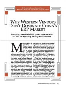
Enterprise requirements model
Enterprise system model
Automated matching
Match and gap analysis
Requirements reformulation
Aligned model
Figure 1: The iterative alignment process
criteria, which vary from a rough logistic characterization of the enterprise to a detailed questionnaire, addressing a variety of issues. The actual requirements of the enterprise are not explicitly considered in this process. Rather, they exist only as part of the human knowledge and reasoning underlying the solution selection. Gaps between the enterprise needs and the system are basically ignored or solved by requiring the enterprise to adapt to an available solution. This solution-driven approach speeds up the implementation, reduces its cost and provides a high quality, bug-free solution. However, these benefits are worthwhile only if and when the enterprise indeed finds a solution that suits its needs. In cases where one or more core processes of the enterprise are unique to the extent that they are not satisfactorily addressed by the predefined criteria, the alignment process cannot be supported. Rather, it is typically done in an ad-hoc, intuitive manner, which requires considerable efforts. Due to the high complexity of enterprise systems, even a small deviation from a given configuration is risky, and requires an extensive verification effort (Ghosh, 2000). Despite the common wisdom that suggests that enterprises can and should standardize their processes in alignment with “best practice” solutions, research reports indicate that it is not always the case in practice. Daneva (1999), who measured requirements reuse in SAP R/3 implementations, found that full reuse was not achieved, although in some cases the rate of reuse was remarkably high. In this paper a requirement-driven approach to the alignment process is introduced. This approach facilitates solution definition by reuse without imposing a predefined set of reuse criteria, and thus
provides a systematic support for both standard enterprises and unique ones. The idea and some aspects related to requirement-driven approaches are presented and discussed (Rolland, 1999; Rolland, 2000; Rolland and Prakash, 2000; Soffer et. al, 2001; Soffer, 2002; Soffer et. al., 2003). A requirement-driven alignment approach emphasizes the enterprise requirements rather than the system’s capabilities and standard solutions. The requirements themselves serve as reuse criteria. These are matched against the capabilities of the system in order to identify the required solution parts and the remaining gaps. The paper presents the suggested alignment process, its input, output, and each of its steps.
2 THE ALIGNMENT PROCESS This section outlines the alignment process, which iteratively seeks a match between a model of the requirements posed by the enterprise and a model that expresses the entire scope of alternative processes supported by the software package. The Process, illustrated in Figure 1, uses a model of the enterprise requirements as input. This model is matched against a pre-existing model of the enterprise system using an automated matching algorithm, which yields an analysis of the matching system options and the gaps identified between the requirements and the system. Based on the analysis, the requirements can be reformulated and matched again. This is repeated until either a satisfactory match is identified or until no reformulation possibility is found. The details of the process steps, inputs and outputs, as appear in Figure 1, are discussed in this section.
2.1 The Enterprise Requirements The enterprise requirements provide the basis for both the selection of the software package and the alignment process. For these two purposes, completeness is not necessarily a desired property of the requirements (Feblowitz and Greenspan, 1998; Finkelstein et. al., 1996; Maiden and Ncube, 1998; Ncube and Maiden, 1999; Soffer et. al., 2001). Since the system implementation involves changes in the enterprise in adaptation to processes supported by the system, the requirement specification should aim at providing the enterprise with the flexibility and adaptability to these available processes, while assessing their suitability. Complete system and interface specification may result in rigidity that would render an exact matching solution within the software package infeasible. Based on this premise, the requirements can be classified into four different types of information (Soffer et. al., 2001): Core system interfaces, whose detailed design is of considerable importance to the enterprise. This is a relatively small set of specified inputs and outputs, typically required for business processes involving interaction with external agents (e.g., reporting to the tax authorities). Core business processes, which must not be changed through the alignment process. The details of these processes are unique, as they generate the competitive advantage of the enterprise. These may include logistic processes, which support an outstanding supply mechanism, or quality assurance processes, which ensure an exceptional quality level. Business rules, which express the enterprise goals (or certain external restrictions that must be followed) and control the business processes. These rules provide the underlying logic, which remains invariant to changes in the business processes in the course of the alignment process. Information objects, which are manipulated by the specified business processes, controlled by the business rules, and participate in the specified interfaces. Since both the system model and the enterprise requirements model relate to business issues, they should be represented in the same modeling language to enable their matching. Rolland (1999, 2000) and Rolland and Prakash (2000) suggest that a map representation be applied in both cases. We apply Object-Process Methodology (OPM) (Dori, 2002), which has been evaluated and found adequate for representing both the requirements and the enterprise system. The evaluation was based on an ontological model of the requirements for evaluating OPM’s expressive power (Soffer et. al, 2001), and
on the ERP-adapted CREWS framework (Rolland and Prakash, 2000), evaluating its content, structure, and notation (Soffer et. al., 2003). Object-Process Methodology, described in detail in Dori (2002), employs two equally important classes of entities: objects and processes, which are connected by structural and procedural links. While many modeling methods require the use of a set of models, each with its diagramming symbols and conventions, to describe different aspects of the system, OPM uses a single graphic tool, the ObjectProcess Diagram (OPD) set, to model the major system’s aspects, structure and dynamics. Simplicity of the model is achieved by an abstractingrefinement zooming mechanism that controls the visibility of the system details. Zooming in and out of entities (objects and processes) enables a topdown analysis, which yields a hierarchical OPD set that specifies the structure and behavior of the system at a spectrum of abstraction levels. The requirements model, rather than being a hierarchical OPD set, is a set of independent OPDs, each representing a single requirement. This way the requirements are expressed independently of each other, so that each one is matched separately with the system model.
2.2 The Enterprise System Model The enterprise system model is a vehicle for aligning the system with the enterprise requirements. As such, it should represent the entire scope of options and business process variants supported by the system and represent dependencies among alternative options. It is obtained once through a reverse engineering process, and may serve as a reference as long as the modeled system has not changed. The reverse engineering process, whose details are in Soffer et. al. (2003), is aimed at capturing the alternative processes and options, which are controlled by the system’s parameters at different application levels. The process follows these levels, identifying the parameter-controlled optionality at each level and representing it in a topdown manner. In the OPM representation, alternative processes are represented by different specializations of a generic process. The details of each entity (object or process) in an OPD may be revealed through refinement in lower-level OPDs, which may, in turn, include other alternative specializations of its entities. The refinement mechanism allows for exact specification of the enterprise system at any level of detail. The resulting OPD set is very large, and consists of hierarchically linked OPDs. These links are managed by representing the OPD set at a meta-
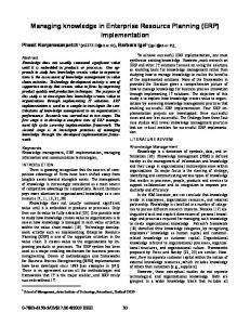
Legend:
General Structural Relation
Aggregation
Process
Instrument link
Effect Link
State
Condition Link
Event Link
Object
Characterization
Generalization-Specialization
Figure 2: An OPM representation of a Purchase Order Handling process
level as a graph, called the system model hypergraph. Each OPD of the system model is a node in the hypergraph, with arcs connecting it to descendant OPDs, which expose details of one or more of the entities in the parent OPD. Each node in the hypergraph is characterized by a logical expression, which provides the logical dependencies among the arcs originating in it. These arcs relate the OPD of that node to the descendant OPDs that specify its entities. Since some of these entities may stand for alternative processes, the logical operator between their corresponding arcs is XOR. Otherwise the logical operator between the arcs is AND. The hypergraph structure and related logical expressions are illustrated by the following example: Figure 2 is an OPD that shows a process of Purchased Goods Receiving, which is related by effect links to Purchase Order and Purchase Order Line, and uses Item as an instrument. This process has three specializations. The occurrence of the specialized processes Location Controlled Receiving and No Location Controlled Receiving is conditioned by the states of the Boolean object "Location Controlled?", which characterizes a Warehouse, while the Noninventory Item Receiving is conditioned by
Item being a Non-inventory Item. Some entities are further refined in other OPDs, listed in Table 1, forming the hypergraph presented in Figure 3. The logical expression among the arcs reflecting the dependencies among the corresponding entities, can now be defined. The three alternative processes, Location Controlled Receiving, No Location Controlled Receiving, and Non-inventory Item Receiving, whose corresponding arcs are to OPDs 2, 3, and 4 respectively, are related by a XOR operator. While the processes Location Controlled Receiving and No Location Controlled Receiving are both related to the objects Warehouse (whose outgoing arc is to OPD 7) and Inventory by Item (arc to OPD 8), the object Inventory by Location (arc to OPD 9) is related to Location Controlled Receiving only. Other objects in the OPD, such as Item (arc to OPD 5), and Purchase Order (arc to OPD 6), are related to all the alternative processes. Each such relation is represented in the logical expression by an AND operator. Therefore, the logical expression that characterizes node 1 is: 5 AND 6 AND (4 XOR (7 AND 8 AND (3 XOR (2 AND 9)))).
1
2
3
4
6
9 8 5
10
7
Figure 3: A part of a system model hypergraph, whose root holds the Purchase Goods Receiving OPD presented in Figure 2
2.3 The Automated Matching
The automated matching of the requirements model and the system model consists of two main steps: Single Requirement Matching (SRM) and Bottom-Up Aggregation (BUA). SRM examines each requirement separately and looks for matching diagrams within the system model. It generates a matching score for each pair 〈R, E〉, where R is a requirement OPD and E is a system OPD. The SRM output serves as input to BUA, which aggregates the matching scores up the system model hypergraph and identifies their feasible combinations. Single Requirement Matching (SRM): assesses the similarity between pairs of OPD portions, each consisting of an OPD expressing a requirement in the requirements model and its counterpart in the system model. As discussed in Section 2.1, the requirements are generally incomplete and represent only the details that are essential to the enterprise,
while the system model is usually more detailed. SRM is the part of the matching algorithm that is designed to resolve this mismatch. SRM computes a matching score for 〈R, E〉 based on two measures: Entity Similarity (ES) and Relational Similarity (RS). ES is the proportion of entities in R that have a matching entity in E, i.e., an entity whose name and type are identical to those of the entity in R. It is computed using a simple query, which compares the entities of each of the system model OPDs with the entities of a given requirement, and counts the entities whose type and name are identical. The query provides a set of candidate matching pairs 〈R, E〉, whose ES score exceeds a given threshold. RS, the Relational similarity, which is assessed for each pair in this set, measures the similarity of the link structure in a pair 〈R, E〉, by an exhaustive search for matching of each link in R. Each link in R
Table 1: The OPDs related to the Purchase Goods Receiving process
OPD number
OPD name
Descendant OPDs
1
Purchased Goods Receiving
2, 3, 4, 5, 6, 7, 8, 9
2
Location Controlled Receiving
5, 6, 7, 8, 9
3
No Location Controlled Receiving
5, 6, 7, 8
4
Non-inventory Item Receiving
5, 6
5
Item
6
Purchase Order
7
Warehouse
8
Inventory by Item
5, 7
9
Inventory by Location
5, 7
10
Supplier
5, 10
may be:
(a) Matched by a link in E, which is of the
same type and relates matching entities for both the source and the destination of the link. (b) Matched by a path in E, which is equivalent to its type and relates matching entities for both the source and the destination of the link. (c) Not matched. A path is a sequence of links and entities, connecting a source entity to a destination entity. A path is considered equivalent to a link of specific type if it can be abstracted to a link of this type. Equivalence is identified on the basis of equivalence rules, defined for each link type in OPM. For a given link type, equivalence rules state link types that are allowed in a path, link types that must be in a path and in some cases their required position: at the source of the path or at its destination. The equivalent path identification enables matching a requirement OPD and a system model OPD despite the mismatch in their abstraction level. The Relational Similarity (RS) of 〈R, E〉 is computed according to the matching results of all the requirement’s links. Thus the overall Matching Score (MS) of a pair 〈R, E〉 is computed as a weighted sum of the two similarity measures, provided neither of them equals zero. Bottom-Up Aggregation (BUA): The Bottom-up Aggregation (BUA) process, which is the second part of the automated matching, provides the feasible combinations of the requirements, whose matching scores have been computed by SRM. The options that are available in an enterprise system can be highly dependent on each other. Hence, a combination of features available in a specific configuration may not be available in other configurations (Koch, 2001). Identifying a set of requirements that are met by the system does not guarantee that their combination is feasible in a single configuration. The system’s internal dependencies may form constraints on the feasible solution. For example, in the Baan ERP system, it is possible to allocate a specific inventory unit to a
specific order (such an action is termed “hard allocation”). However, this option is valid only if the warehouses are not location controlled, that is, in a configuration where the value of the parameter “Location Control Implemented?” is “No”. Separately verifying that the system is capable of handling requirements of hard allocation and location control would yield a positive answer, despite the fact that their combination is not feasible. BUA aims at providing a solution space, which enumerates the feasible combinations of requirements satisfied by the system along with their matching scores. It relies on the logical expressions related to the nodes of the system model hypergraph in order to achieve this goal. The BUA, formally specified in Soffer (2002), starts after the SRM has computed Matching Scores for all the given requirements matched by OPDs of the system model. The computed Matching Scores are related to a set of nodes in the system model hypergraph, whose OPDs match the requirements. The BUA sorts the nodes of this set according to their distance from the root node, starting with those whose distance is maximal. At each step it goes one level up and aggregates the Matching Scores for the upper level, by placing them in the corresponding positions of the logical expression of the upper-level node. The logical expression of this node holds a local matched requirements combination, which specifies the feasible combination of requirements matched by the OPD in the current node and all its descendants. When going up to the next level, the local combinations are aggregated again. This procedure is repeated until the top-level diagram (the root node of the hypergraph) is reached. Its combined expression holds all the requirement results aggregated up the system model hypergraph and their logical relations, providing the matching options of the enterprise system with respect to the enterprise requirements. The BUA steps are illustrated by the following example: assume that four requirements specifying the issues listed in Table 2 are matched against the part of the system discussed in Section 2.2 (see
Table 2: Four example requirements Requirement
Description
a
Supplier object structure
b
Item object structure
c
Inventory object structure
d
Purchase receiving process
Table 3: BUA steps example Step Initial SRM result BUA first step BUA Second step BUA third step
Node 2 3 5 9 10 6 8 9 2 3 4 1 (root)
Distance from root (in arcs) 1 1 3 2 3 2 2 2 1 1 1 0
Local requirement combination d(0.5) d(0.8) b(0.6) c(1) a(0.7) b(0.6) AND a(0.7) b(0.6) c(1) AND b(0.6) d(0.5) AND [c(1) AND b(0.6)] AND [b(0.6) AND a(0.7)] AND b(0.6) d(0.8) AND b(0.6) AND [b(0.6) AND a(0.7)] AND b(0.6) [b(0.6) AND a(0.7)] AND b(0.6) b(0.6) AND [b(0.6) AND a(0.7)] AND [[[b(0.6) AND a(0.7)] AND b(0.6)] XOR [b(0.6) AND [[d(0.8) AND b(0.6) AND [b(0.6) AND a(0.7)] AND b(0.6)] XOR [[d(0.5) AND [c(1) AND b(0.6)] AND [b(0.6) AND a(0.7)] AND b(0.6)] AND [c(1) AND b(0.6)]]]]]
Figures 2-3 and Table 1). The course of the BUA, given in Table 3, starts when the SRM has identified system model OPDs that match the given requirements (in nodes 2, 3, 5, 9, and 10 of the hypergraph) and computed their Matching Scores, which are given in brackets by the requirement (e.g., the OPD in node 2 matches requirement d with MS=0.5). Starting at the bottom of the hypergraph, the BUA aggregates the local matched requirements combination one level up at each step, by placing the results in the logical expression of each node. For example, in the first BUA step node 6 aggregates its two descendants, nodes 5 and 10, thus its local requirement combination is b(0.6) AND a(0.7). In the given hypergraph all the node logical expressions consist of AND operators, except for the root node, whose logical expression, discussed in Section 2.2, is: 5 AND 6 AND (4 XOR (7 AND 8 AND (3 XOR (2 AND 9)))). The aggregated matched requirements combination of the root, obtained in the third BUA step, can be reduced to: b(0.6) AND a(0.7) AND [d(0.8) XOR [d(0.5) AND c(1)]], indicating the following: • Requirements a and b, regarding the structure of the Item and Supplier objects, are not fully matched. These gaps may be solved by reformulation activities, or require a customization decision. • Requirement c, regarding the structure of the Inventory object, is fully matched by the
Inventory by Location OPD (number 9) in the system model. • Requirement d, regarding the Receiving process, is partially matched by two system alternatives: Location Controlled Receiving (number 2) with an MS of 0.5 and Non-location Controlled Receiving (number 3) with an MS of 0.8. It seems that Non-location Controlled Receiving is a better match (despite a minor gap that should be resolved). However, this process is not feasible in combination with the Inventory by Location object, which satisfies requirement c. Therefore, a combination gap is identified. The implementation team should now investigate the possibility of improving the match of Location Controlled Receiving by reformulation activities, or consider a software customization.
2.4 Requirements reformulation Reformulating the requirements involves three types of action: splitting, abandoning, and mapping. Splitting entails splitting composite requirements into simpler ones. A composite requirement includes at least two entities that may be revealed in lower-level OPDs. splitting addresses required processes, which are not standard process defined in the system model, but all their subprocesses (steps) exist as parts of other processes. In such cases, it may be possible to “assemble” the required process as a sequence of these steps. In order to verify this possibility, each of the process
steps and its required interface should be examined as a separate requirement. Abandoning is the second way of reformulating requirements. The automated matching may identify some requirements as not being satisfied by the system, or as contradicting other requirements of higher priority. In such cases a software customization may be considered. Alternatively, if an unsatisfied requirement is of a lesser importance, or if some activities may be handled manually without involving the system, that requirement can be abandoned. Mapping – each time a requirement is modeled and expressed using the system’s terminology, some decisions of mapping the enterprise entities to entities of the system are made. Different mappings may yield different matches. Such mappings are applied frequently in manual alignments, where considerable effort is required to verify their appropriateness. Mapping requires the implementing team members to think creatively and to apply a high level of expertise and knowledge of the system and its internal relations. Due to the complexity and integrative nature of enterprise systems, the manual verification of the consequences of a mapping decision is a difficult task. Every decision may affect many other parts of the system, and each one of them must be checked and tested in order to ensure their correct operation. In the iterative alignment process, new mapping decisions still rely on creative thinking, but their verification is accomplished by the automated matching, which instantaneously scans the entire system model, identifies the effects of the reformulated requirement and potential contradictions with other requirements.
2.5 The Aligned Process Model The Aligned Process Model, which is the output of the alignment process, is a specialization of the system model, consisting of the OPDs identified as satisfying the requirements. Some of these OPDs can be an “assembly” of parts belonging to different OPDs in the initial system model. Others may include new objects, processes and links, required as software customizations. In addition to the business process design, the aligned process model provides the system configuration, i.e., the control parameter values, to support a set of specified processes. Two other outputs are a list of recommended software customizations and a complete system-enterprise mapping, that corresponds to the selected solution as specified in the aligned process model. This mapping serves for planning the conversion and
migration of data from the existing information system to the new enterprise system.
3
CONCLUDING DISCUSSION
The problem of identifying and analyzing the gaps between a system and the requirements of an enterprise, and aligning the system to the needs of the enterprise, is at the heart of enterprise systems implementation. Adequate solution to this problem is crucial for a successful implementation and the competitive edge of the implementing enterprise. The approach presented in this paper for solving this gap analysis and alignment problem provides a systematic support for the alignment process in both standard enterprises and unique ones. Unlike solution-driven methods, which apply a predefined set of criteria for the process selection, this approach facilitates reuse on the basis of the enterprise requirements. Therefore it benefits from reuse without being restricted by a predefined set of criteria and standard solutions. The approach employs an automated matching, which has been implemented in a prototype of a support tool. Matching between a model of the enterprise requirements and a model of the ERP system capabilities, the tool addresses two difficult problems. One is identifying a match between an incomplete requirements model and a complete and detailed system model. This is achieved by using a relational similarity measure that, unlike previous works (Massonet and Lamsweerde, 1997; Sutcliffe and Maiden, 1998; Lai et. al., 1999), allows matching links between non-neighboring entities, i.e., entities that are not directly related in the system model. The other problem is the existence of dependencies among the system’s options, which poses constraints on the feasibility of combining all the satisfied requirements in a single configuration of the system. This problem is solved by the solution space that enumerates the feasible combinations of requirements in the system. The alignment process was tested in an experimental study, whose details are provided in Soffer (2002). The study applied the alignment process to 35 requirements defined in a real-life implementation project, matched them against a partial ERP system model (including 119 OPDs), and compared the recommendations that were obtained with the real-life decisions. The comparison demonstrated the viability of the approach and the ability of the process to provide an adequate solution to the problem. Despite some difficulties that were spotted, the automated matching successfully identified the major gaps between the capabilities of the system and the
requirements of the enterprise, and provided the information needed for decision-making. The main difficulty that was detected in the study is in the semantic matching of the entity names. As explained in Section 2.4, due to the high level of expertise required for making mapping decisions, the iterative process relies on human reasoning for naming the entities in the requirements model. These names can be iteratively altered through other mapping decisions. Nevertheless, it seems that the naming task is too complex for human reasoning alone. The participants in the study indicated that a thesaurus support could be helpful, and save iterations time. Practical implications of using the approach, such as the expected implementation time saving in a real life project, are hard to estimate at this point. However, the results of the study indicate that compared to a manual alignment, which is currently performed when standard solutions are not applicable, significant time saving as well as a higher quality solution can be achieved. A largescale study or an action research, in which the alignment process would be applied in a real-life project may provide better indications. REFERENCES Bingi, P., Sharma, M., and Godla J., 1999. Critical Issues Affecting an ERP Implementation. Information Systems Management, 16, 7-14. Curran, T. A and Ladd, A., 1999. SAP R/3 Business Blueprint: Understanding Enterprise Supply Chain Management, 2nd ed., Prentice Hall, NJ. Daneva, M. 1999., Measuring Reuse in SAP Requirements: a Model-based Approach. In SSR’99, Proceedings of the Fifth Symposium on Software Reusability, ACM Press. 141-150. Davenport, T. H., 1998. Putting the Enterprise into the Enterprise system. Harvard Business Review 121-131. Dori, D. 2002. Object Process Methodology – A Holistic Systems Paradigm. Springer Verlag, Heidelberg, New York. Feblowitz, M.D. and Greenspan, S. J., 1998. Scenario-Based Analysis of COTS Acquisition Impacts, Requirements Engineering, 3, 182-201. Finkelstein, A. C. W., Spanoudakis, G. and Ryan, M., 1996. Software Package Requirements and Procurement. In Proceedings of the 8th International Workshop on Software Specification and Design, IEEE Press Los Alamitos. 141-145. Ghosh, J., 2000. SAP Project Management, McGraw-Hill, New York. Holland, C.P. and Light, B. A 1999. Critical Success Factors Model for ERP Implementations. IEEE Software, 16, 30-35.
Koch, C. 2001. BPR and ERP: Realising a Vision of Process with IT. Business Process Management Journal, 7, 258-265. Lai, L. F., Lee, J., and Yang, S. J., 1999. Fuzzy Logic as a Basis for Reusing Task-Based Specifications. International Journal of Intelligent Systems, 14, 331-357. Light, B. 2001., The Maintenance Implications of the Customization of ERP Software, Journal of Software Maintenance: Research and Practice, 13, 415-429. Maiden, N. A. M. and Ncube, C., 1998. Acquiring COTS Software Selection Requirements. IEEE Software, 15, 46-56. Massonet, P. and Lamsweerde, A.V., 1997. Analogical Reuse of Requirements Frameworks. In RE’97, Proceedings of the Third IEEE Symposium on Requirements Engineering, IEEE Press Los Alamitos CA. 26-37. Ncube, C. and Maiden, N. A. M. 1999., Guiding Parallel Requirements Acquisition and COTS Software Selection. In RE’99: Proceedings of the IEEE International Symposium on Requirements Engineering, IEEE Press Los Alamitos. 133-140. Post, H. A. and Van Es, R. (Eds)., 1996. Dynamic Enterprise Modeling: A Paradigm Shift in Software Implementation. Kluwer, Dordrecht.. Rolland, C. 1999. Requirements Engineering for COTS Based Systems. Information and Software Technolog,y 41, 985-990. Rolland, C., 2000. Intention Driven Component Reuse. Information Systems Engineering: State of the Art and Research Themes, Springer-Verlag, Berlin. 197-208. Rolland, C. and Prakash, N., 2000. Bridging the Gap Between Organizational Needs and ERP Functionality. Requirements Engineering 180-193. Soffer, P., Golany, B., and Dori B., 2003. ERP Modeling: a Comprehensive Approach, Information Systems (to appear). Soffer, P., Golany, B., Dori B. and Wand, Y., 2001. Modelling Off-the-Shelf Information Systems Requirements: An Ontological Approach. Requirements Engineering, 6. 183-198. Soffer P., 2002., A Methodology for Adapting an ERP System to the Needs on an Enterprise, PhD Thesis, Technion –Israel Institute of Technology. Sutcliffe, A. and Maiden, N. A. 1998. The Domain Theory for Requirements Engineering. IEEE Trans. on Software Engineering, 24, 174-196. Themistocleous, M., Zahir, I., and O’Keefe, R. M., 2001. ERP and Application Integration. Business Process Management Journal, 7. 195-204. Van Es, R., 1998. Dynamic Enterprise Innovation, Baan Business Innovation, The Netherlands.