X-ray beam-film alignment errors in all subsequent radiographs using the 'ideal' reference. Bitewing .... (
Alignment errors in bitewing radiographs using uncoupled positioning devices M.K. Shrout*, C.F. Hildebole and M.W. Vannier" "Department of Oral Diagnosis and Patient Services. Medical College of Georgia. School of Dentistry. Augusta. Georgia and "Mallinckrodt Institute of Radiology. Washington University. St Louis. Missouri. USA
Received 10 September 1991 and in final form 24 February 1992 Errors in X-ray beam alignment account for many of the exposure errors in bitewing radiography. A new method for measuring these alignment errors is described. The alignment accuracy of two different models of inexpensive plastic positioning devices, used for bitewing radiography, were quantified and compared. The technique involves documenting the alignment of an 'ideal' reference radiograph and successive exposures. It permits calculation of X-ray beam-film alignment errors in all subsequent radiographs using the 'ideal' reference. Bitewing radiographs were taken on 61 patients and 19 of these were re-radiographed at 6-month intervals over a 2-year period, providing a total of 156 radiographs for the study. Horizontal and vertical angular deviations were measured and total alignment errors calculated for each radiograph. The average angular alignment error was less than 2° total angular error (1.3-2.4°, 95% confidence intervals). It is concluded that these devices can be used when X-ray beam-film alignment error below 2S is acceptable. Keywords: Radiography, bitewing; radiography, dental; photogrammetry Dentomaxillofac. Radiol., 1993, Vol. 22, 33-37, February
Positioning devices are designed to help the operator produce optimal radiographs by assisting in the alignment of the central X-ray beam with the film. Errors in alignment can affect such routine tasks as measuring alveolar bone loss 1.2 and diagnosing proximal caries '>' from standard bitewing radiographs. Improper alignment of the film and X-ray beam has been shown to be a primary source of error in serial image assessment in subtraction radiography". This error may be greater for serial bitewing radiographs when inexpensive plastic positioning devices are employed. Uncoupled techniques, in which the positioning devices are not physically attached to the X-ray tubehead, rely on patient cooperation and operator judgement to insure the correct alignment. Exposures fall within a range around the ideal, with 71% of all angulation errors due to operator misalignment of the X-ray heads. Coupling the X-ray machine to the positioning device can produce serial radiographs with a high degree of geometrical uniforrnity'r". These methods, however, have been described as awkward, cumbersome, time consuming and uncomfortable for the patient'). 10. These limitations can be overcome by using the coupled apparatus to expose a reference radiograph prior to using the device in the usual uncoupled manner for patient radiographs. The reference radiograph, taken in ideal alignment with the X-ray beam, serves as the archetype and is used to calculate departures from the
ideal for all subsequent patient radiographs. It should be noted that while good radiographic technique dictates patient films be placed parallel to the long axes of the teeth, measurement of the main beam-film alignment is independent of the placement of the film in the oral cavity or the position of the occlusal plane in space. Duckworth et al. 10 described a positioning device 'to provide for consistent reproduction of both geometric and densitometric exposure parameters'. It included two orthodontic wires, one square and one round, placed coaxially on the device, perpendicular to the film. These wires could be differentiated on exposed film by their shape. With this method, a reference radiograph is not made. Angular variations between successive radiographs can be calculated; however, the usefulness of the device is limited to the detection of changes in angulation only. This paper describes a technique where an ideal reference radiograph is exposed so that angular variations from this optimal alignment can be calculated for all subsequent exposures. Using this technique, the alignment accuracy for two different models of plastic positioning devices used for bitewing radiography was evaluated. A secondary objective was to determine if the alignment accuracy for one of the devices would change with recall appointments. Proper placement of the film within the dental arch was not addressed in this study. Dentomaxillofac. Radiol., 1993, Vol. 22, February 33
Bitewing alignment errors: M. K. Shrout et al.
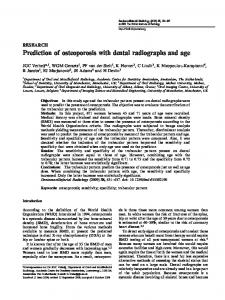
Figure.t a, Intrax Positioning System, with the positioning ring on indicator bar for bitewing exposure. b. Kwik-Bite device; no positioning ring is used with this system
Materials and methods The positioning devices Two models of positioning devices were used in this study: The Intrax Positioning System and the KwikBite device. The Intrax Positioning System (Flow X-ray Corp., West Hempstead, NY, USA) consists of a film holder, biteplate , indicator bar, and positioning ring (which fits on the bar, Figure la). The Kwik-Bite device (Hawe-Neos Dental, Gentilino , Switzerland) consists of a film holder, a biteplate , an index, and an indicator rod. It has no ring (Figure Ib).
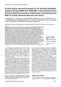
Both devices were modified by placing a I-mm piece of arch-stop tubing (American Orthodontics, Sheboygan, WI, USA) in contact with the film clamp (Figure 2a). The tubing in this location is within I mm of the film on the Intrax and in contact with the film on the Kwik-Bite device (Figure 2b). The round wire is placed 16 mm from the film and coaxial with the path of the main beam. The tube and the round wire produce a circle and dot projection on the exposed radiographs (Figure 3) which were used to document the alignment of the film and beam.
The reference radiograph
a
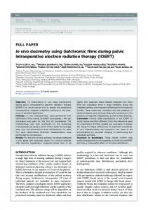
A positioning ring was adapted for use with each positioning device. Because the Kwik-Bite does not include a ring, one from an Intrax Positioning System was used. The ring was placed flush against the collimating cylinder and invested in tray acrylic so that a collar of acrylic (CaE tray, Coe Laboratories, Chicago, IL, USA) surrounded the end of the cylinder (Figure 4). The acrylic collar functioned as a template by providing optimal coupling between the X-ray tubehead and each individual device for exposure of the reference radiograph (Figure 3a). To insure easy reading of superimposed radiographs, the reference film was exposed using low impulse times, 15 impulses at 70 kVp and lOrnA (GE 1000, Gendex Corp, Milwaukee, WI, USA) with D-speed film (DF 57, Eastman Kodak, Rochester, NY, USA). The relationship of the circle to the dot on the exposed reference radiograph defines the ideal alignment of the film and beam and was used to calculate deviations from ideal in the subsequent patient radiographs.
Patient radiographs
Figure 2 a. Close-up showing position of alignment wire and tube (arrows) on Intrax system. The tube is attached to the film holder. b. Close-up showing position of alignment wire and tube on Kwik-Bite device
34
Dentomaxillofac. Radiol., 1993, Vol. 22, February
With the approval of the University's Human Assurance Committee, 156 bitewing radiographs were obtained of patients who had been referred for scheduled examinations, using standard uncoupled techniques with the modified positioning devices (Figure 3b). Three sets of radiographs were collected: (I) Initial bitewings taken on 45 patients with the Intrax.
Bitewing alignment errors: M. K. Shrout et al.
Figure 3 a. Reference radiograph showing the circle and dot projections of thc tube and wire. b. A bitewing radiograph showing the circle and dot projections
position of the tube's circular projection is held constant by its contact with the film surface; therefore, a is proportional to the displacement of the dot projected onto the film by the wire (W). The measurement of the distance between the dots on the reference and patient films is represented by 0 in Figure 5, where: D=B-C
(2)
By definition and design the relative locations of the dot and circle identify the zero degree reference (perpendicular to the film) for the tube-wire projection. Therefore, in Figure 5:
¢> = 0,
(2)
and (4)
C=O
Figure 4 A modified positioning ring in place on the end of the X-ray collimating cylinder. for coupled reference radiographs
Substituting (3) into equation (1): (5)
a=ljJ
(2) Recall appointment radiographs taken at 6-month intervals (using 19 of the same patients and Intrax devices as used for the initial exposures). (3) Initial appointment radiographs, of a separate group of 16 patients, taken with the Kwik-Bite device (recall radiographs were not available for this device).
and substituting (4) into (2): (6)
D=B Thus (Figure 5): tan ljJ = BI16
(7) 16mm
Angular error calculations The developed radiographs were superimposed over their respective reference radiographs, so that the circles were perfectly overlapped and the respective edges of the films parallel. The separation of the dots on the two films was measured in x (horizontal) and y (vertical) directions relative to the film. Measurements of these distances were made from the radiographs with a vernier caliper and the mean x, y and total angular errors were determined as follows: The angular error (a) is defined as the difference between the actual exposure angulation (ljJ) and the ideal angulation (¢» (Figure 5). a=ljJ-¢>
(1)
For the sake of brevity, only the calculations for the Kwik-Bite device are discussed. With this system, the
o B
c '-TUbe ""-Film
Figure 5 Schematic of angulation calculations. Alpha (a), the angular error; T (Tube), arch-stop tubing marker; D. displacement of the wire (W) due to angulation error; C, displacement of the wire from the perpendicular, caused by the ideal angulation projection (