Sep 16, 2010 - cGaN. 33. ( c0. GaN c0. AlN. )2 . (3). Rc and ts are the radius of the core and thickness of the shell, respectively. The in-plane strain εplane and ...
Home
Search
Collections
Journals
About
Contact us
My IOPscience
The structural properties of GaN/AlN core–shell nanocolumn heterostructures
This article has been downloaded from IOPscience. Please scroll down to see the full text article. 2010 Nanotechnology 21 415702 (http://iopscience.iop.org/0957-4484/21/41/415702) View the table of contents for this issue, or go to the journal homepage for more
Download details: IP Address: 132.168.9.41 The article was downloaded on 01/12/2010 at 08:21
Please note that terms and conditions apply.
IOP PUBLISHING
NANOTECHNOLOGY
Nanotechnology 21 (2010) 415702 (7pp)
doi:10.1088/0957-4484/21/41/415702
The structural properties of GaN/AlN core–shell nanocolumn heterostructures K Hestroffer1, R Mata2 , D Camacho3 , C Leclere4 , G Tourbot1,5, Y M Niquet3 , A Cros2 , C Bougerol1 , H Renevier4 and B Daudin1 1
CEA-CNRS group ‘Nanophysique et Semiconducteurs’, Institut N´eel/CNRS-Universit´e J Fourier and CEA Grenoble, INAC, SP2M, 17 rue des Martyrs, 38 054 Grenoble, France 2 Materials Science Institute, University of Valencia, PO Box 22085, E46071, Valencia, Spain 3 CEA Grenoble, INAC, SP2M/L Sim, 17 rue des Martyrs, 38 054 Grenoble, France 4 Laboratoire des Mat´eriaux et du G´enie Physique, Grenoble INP—MINATEC, 3 parvis L N´eel 38016 Grenoble, France 5 LETI-DOPT, CEA Grenoble, 17 rue des Martyrs, 38 054 Grenoble, France
Received 5 August 2010, in final form 30 August 2010 Published 16 September 2010 Online at stacks.iop.org/Nano/21/415702 Abstract The growth and structural properties of GaN/AlN core–shell nanowire heterostructures have been studied using a combination of resonant x-ray diffraction, Raman spectroscopy and high resolution transmission electron microscopy experiments. For a GaN core of 20 nm diameter on average surrounded by a homogeneous AlN shell, the built-in strain in GaN is found to agree with theoretical calculations performed using a valence force field model. It is then concluded that for an AlN thickness up to at least 12 nm both core and shell are in elastic equilibrium. However, in the case of an inhomogeneous growth of the AlN shell caused by the presence of steps on the sides of the GaN core, plastic relaxation is found to occur. Consistent with the presence of dislocations at the GaN/AlN interface, it is proposed that this plastic relaxation, especially efficient for AlN shell thickness above 3 nm, is promoted by the shear strain induced by the AlN inhomogeneity.
structures led to similar conclusions [3], the reduction of the QCSE being attributed in both cases to a reduction in the piezoelectric polarization in NWs [4]. AlGaN/GaN quantum discs in nanowires have also been studied. Time resolved data also showed that the optical properties of thick GaN insertions exhibited an oscillator strength reduction assigned to the presence of an internal electric field [5, 6]. The above considerations have naturally nurtured the interest in core–shell heterostructures, with the aim of growing non-polar nitride NW heterostructures. As GaN NWs grown by catalyst-free plasma-assisted molecular beam epitaxy (PAMBE) are oriented along the c-axis, their lateral walls are oriented perpendicularly to c, i.e. along a nonpolar direction. More precisely, it has been established ¯ ) that the walls of hexagonally shaped GaN NWs are (1100 planes [7–9]. This opens the way to the growth of non-polar radial heterostructures while also raising the issue of strain relaxation in GaN/AlN core–shell heterostructures through dislocation formation beyond a given critical thickness, which
1. Introduction It is now well known that the optical properties of nitride polar heterostructures are governed to a large extent by the presence of the internal electric field built-in along the c-axis, a combination of spontaneous polarization and piezoelectric components. This statement also holds in the case of nitride nanowire (NW) heterostructures: it has been recently shown that the photoluminescence of GaN insertions in AlN NWs exhibits a marked red-shift, a signature of the quantum confined Stark effect (QCSE) associated with the presence of an internal electric field [1]. Although the piezoelectric component tends to vanish for thick GaN insertions, due to the easy elastic strain relaxation resulting from the NW geometry, it is expected that the optical properties of such insertions will still be dominated by the presence of the piezoelectric field and the oscillator strength decrease resulting from it. Along these lines, it has actually been shown that for InGaN/GaN quantum wells in nanowires the QCSE is strongly reduced compared to two-dimensional quantum wells emitting in the same spectral region [2]. Analysis of InGaN/GaN NWs light emitting diode 0957-4484/10/415702+07$30.00
1
© 2010 IOP Publishing Ltd Printed in the UK & the USA
Nanotechnology 21 (2010) 415702
K Hestroffer et al
has been recently addressed from a theoretical point of view [10]. In the case of axial GaN insertions in AlN NWs, it has been found that the formation of an AlN shell assigned to a non-negligible radial growth of AlN sections could not be avoided [11]. Furthermore, it has been recently demonstrated that the growth of this AlN shell is associated with the formation of misfit dislocations, due to the peculiar shape of the GaN insertions which leads to an AlN shell thickness locally larger than the critical one [12]. More generally, the issue of the critical thickness in GaN/AlN, GaN/Alx Ga1−x N and Inx Ga1−x N/GaN core–shell NW heterostructures is a crucial one from both basic and applied perspectives, in the context of realizing efficient non-polar light emitting diodes (LEDs) in the visible and UV range. Limiting ourselves to the case of GaN/AlN in the present paper, it is our aim to determine the structural properties of GaN NWs covered with AlN shells of various thicknesses, using a combination of Raman spectroscopy, high resolution transmission electron microscopy (HRTEM) and xray diffraction (XRD) supported by theoretical calculations in the framework of an atomistic valence force field approach. It will be shown that the value of the strain and the relaxation mechanisms depend on the homogeneity of the AlN shell around the GaN core.
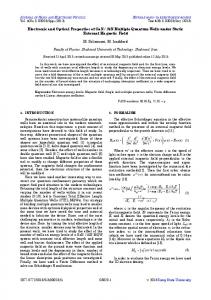
Figure 1. Raman shift of the E 2h mode of GaN as a function of the AlN shell thickness. The value of 566.28 cm−1 , corresponding to plain GaN NWs, has been taken as reference. Errors in the AlN shell thickness—of the order of 20% of the nominal values—are not displayed here for the sake of clarity.
3. Results Room temperature μ-Raman measurements were performed in the backscattering configuration along the axis of the NWs by means of a Jobin-Yvon T64000 spectrometer equipped with a Si charge-coupled device detector and a confocal microscope. The 514.53 nm line from an Ar+ ion laser was used as the excitation source. In order to focalize the laser and collect the emitted light into the spectrometer, a 100× microscope objective was employed (N.A. = 0.90). The dimensions of the laser spot focused on the samples was around 1 μm2 and the incident power density was kept in the 105 W cm−2 range to avoid heating the sample. An edge filter was placed in front of the spectrometer entrance to block the elastically scattered light. The analysis of the Raman signal from different spots on the samples indicated that they are homogeneous. Figure 1 shows the evolution of the Raman shift of the E 2h mode of GaN as a function of shell thickness. The frequency of this mode in a plain GaN NW sample (566.28 cm−1 ) is taken as reference. It is well known that the frequency of the E 2h mode is sensitive to strain, so that changes in its Raman shift are correlated with strain changes in the core material [17]. With increasing shell thicknesses below 3 nm, the mode rapidly shifts to the blue in the region of small coverage, as a consequence of the increasing compression of the core. However, for shell thicknesses above 3 nm, this trend changes abruptly and the frequency shift of the mode remains almost constant at 5 cm−1 . The mean values of the in-plane (εplane ) and axial (εc ) strain components are related to Raman shift data by means of the deformation potential approximation [18]:
2. Samples Samples were grown by plasma-assisted molecular beam epitaxy on Si(111) substrates previously deoxidized by HF (10%) and thermally outgassed until the appearance of the 7 × 7 surface reconstruction. To ensure the reproducibility of the substrate temperature, we relied on the Ga desorption time calibration method described in [8]. A thin AlN buffer layer was grown prior to GaN deposition in order to improve the NW orientation [13]. The GaN NWs were then grown under N-rich atmosphere and high substrate temperature conditions corresponding to a Ga desorption time of 6 ± 0.2 s (about 850 ◦ C). These NWs constitute the cores of the structures studied here. Their typical length is 250 nm, for a diameter of about 20 nm. Following the growth of the GaN cores, AlN was deposited on their top, which simultaneously resulted in the formation of an AlN shell around the GaN core, due to the significant lateral growth of AlN assigned to the limited diffusion of Al on the NW facets [11, 14–16]. It has actually been checked that in our experimental conditions, the ratio between the vertical and lateral growth rates of AlN (vv /vl ) was about 30. Based on this calibration, ten samples with nominal shell thicknesses ranging from 1 to 12 nm were grown. The effective AlN shell thicknesses were assessed by HRTEM analysis of a significant number of as-grown NWs (about ten in each case). It was found that for a given sample, the average shell thickness satisfactorily matches the nominal one. The shell thickness distribution around the average value was estimated to be of the order of 20% of the nominal value, taking into account the inhomogeneities of the AlN shell on a given nanowire as well as the fluctuations of the AlN shell thickness from one nanowire to another.
�ω = 2aεplane + bεc
(1)
where the phonon deformation potentials a and b for the E 2h mode are taken from [19]. However, further processing of the Raman data requires an additional hypothesis on the relationship between εplane and εc . 2
Nanotechnology 21 (2010) 415702
K Hestroffer et al
Figure 3. The calculated in-plane strain εplane (a) and the axial strain εc (b) along the axis of GaN/AlN core–shell nanowires, as a function of the shell thickness ts , for different core radii Rc . The dashed lines in figure 3(b) are equation (2).
Figure 2. Maps of εplane (a) and εc (b) calculated in the cross section of a GaN/AlN core–shell nanowire for a core radius Rc = 10 nm and a shell thickness ts = 3 nm. The maps were obtained after computation of the strains with an atomistic valence force field model adapted to wurtzite materials. Note that these strains are calculated with respect to the relaxed value for each material.
In the continuum elasticity theory, εc then decouples from the other strains and minimizes: GaN core 2 AlN shell 2 E = 12 Acore c33 (εc ) + 12 Ashell c33 (εc ) ,
(2)
where Acore and Ashell are the cross sectional area of the core and shell, and c33 is the macroscopic elastic constant. The strain εccore which minimizes equation (2) and fulfils the 0 0 continuity equation (1 + εccore )cGaN = (1 + εcshell )cAlN , where 0 c is the relaxed c lattice parameter, is
For that purpose, the strains in the core–shell nanowires were computed with an atomistic valence force field (VFF) model adapted for arbitrary wurtzite materials [20]. Nanowires ¯ } facets were with a hexagonal cross section and {1100 considered in the simulations. The elastic energy of the nanowires was minimized with respect to the atomic positions, accounting for elastic relaxation only (no dislocations were introduced). The strains εplane and εc were then computed from the equilibrium atomic positions. The maps of εplane = (ε xx + ε yy )/2 and εc = εzz in the cross section of a GaN/AlN core–shell nanowire ( Rc = 10 nm, ts = 3 nm) are plotted in figure 2. As expected, the AlN shell is under tensile strain, while the GaN core undergoes compressive strain (note that strain is calculated with respect to the relaxed value for each material). The axial strain εc is very homogeneous in the core and shell, and is much larger than the in-plane strain εplane . We can actually understand the main trends for εc by neglecting εplane in the elastic energy.
0 0 − cGaN F cAlN where 0 1+F cGaN �2 �2 AlN � 0 AlN � 0 cGaN cGaN Ashell c33 ts2 + 2 Rc ts c33 F= = . (3) GaN 0 GaN 0 Acore c33 Rc2 cAlN c33 cAlN
εccore =
Rc and ts are the radius of the core and thickness of the shell, respectively. The in-plane strain εplane and the axial strain εc along the axis of the nanowire are plotted in figure 3 as a function of ts , for different core radii Rc . As discussed above, the in-plane strain in the core is one order of magnitude smaller than the axial strain. The fluctuations of εplane visible in figure 3(a) are due to the discontinuous change in the number of atomic planes in the shell with increasing ts . The 3
Nanotechnology 21 (2010) 415702
K Hestroffer et al
also the Bragg reflection of the GaN core. It was then possible to extract the Ga scattering contribution (modulus of the Ga partial structure factor) and the Al and N scattering contribution (modulus of the Al and N partial structure factor) through the analysis of MAD measurements [21, 22]. Focusing on the Ga contribution, we pointed out the position of the spot in the reciprocal space and determined the ¯ ) reflections a and c lattice parameters of the GaN core. (1015 being more sensitive to the out-of-plane parameter c, they were used to extract the strain εc expressed as
εc =
above model reproduces very well the variations of εc with the core radius and shell thickness. Equation (3) shows that the strains are, to first order, distributed between the core and shell proportionally to their respective cross sectional areas. The strains would be approximately balanced between the core and shell when Acore = Ashell , while at low shell thickness εccore is found to increase linearly with ts : AlN ts c33 ≈2 GaN Rc c33
�
0 cGaN 0 cAlN
�2
0 0 cAlN − cGaN . 0 cGaN
(5)
0 where cGaN is the relaxed c parameter of GaN, cGaN is the 0 strained one, lGaN = 4.80 is the value of the Miller index l of relaxed GaN in the relaxed AlN reciprocal space and lGaN is the value obtained from the (10–15) reciprocal space maps of the strained GaN core. Similarly, the (30–32) reflections were used to determine the in-plane strain εplane through an equivalent expression relating the a lattice parameter to the Miller index h . These strains εplane and εc are plotted in figure 4 as a function of the shell thickness (open and full triangles). Note that εplane is equal to ε xx for XRD experiments whereas it is equal to (ε xx + ε yy )/2 in the case of Raman data. However, for the sake of simplicity, we used the generic term of εplane in order to characterize either (ε xx + ε yy )/2 or ε xx for Raman or XRD experiments, respectively. Despite small fluctuations, the in-plane strain εplane is close to zero which means that the a lattice parameter of the GaN core is not or very weakly strained by the AlN shell. Yet, εc increases with increasing shell thickness up to about 3 nm, consistent with Raman spectroscopy measurements. Indeed, it is found that both resonant XRD and Raman spectroscopy agree remarkably while differing drastically from the theoretical calculations for AlN shells thicker than 3 nm. At this point, it has to be underlined that whereas XRD/Raman techniques provide averaged information on an ensemble of NWs, calculations were performed for ideal (perfect) NW heterostructures. Yet, scanning electron microscopy (SEM) in transmission mode revealed that the wires often exhibit an asymmetrical AlN shell and a bent GaN core (figure 5). Then, in order to get a deep insight into the strain state of the AlN shell as well as to study the effect of shell asymmetry, complementary high resolution transmission electron microscopy (HRTEM) experiments were carried out using a Jeol 4000EX microscope operated at 400 kV (Cs = 1 mm) on samples having different shell thicknesses and homogeneities. It was therefore possible to analyze both straight and bent heterostructures by choosing in each case a proper set of single NWs. For this purpose, the nanowires were scraped off the substrate and dispersed on a Cu microscope grid covered with a holey carbon film. HRTEM images were analyzed by the ¯ ) or geometrical phase analysis method [23] using either (1010 (0002) reflections in the Fourier transform in order to get maps of the lattice parameters, a and c, respectively. The case of straight NW heterostructures with a symmetrical AlN shell is illustrated in figure 6(a). It shows
Figure 4. In-plane (empty symbols) and axial (full symbols) strain within the GaN core. The circles and triangles are respectively related to Raman and resonant XRD data. Note that the empty circles depict the approximation εplane ∼ 0%. The squares were obtained from HRTEM data for wires with a symmetrical shell, the star for a wire with an asymmetrical shell. The dashed lines corresponding to the calculations for a core radius of 10 nm are reproduced from figure 3 for comparison with the experimental data. Errors in the AlN shell thickness—of the order of 20% of the nominal values—are not displayed here for the sake of clarity. (This figure is in colour only in the electronic version)
εccore
0 0 − lGaN cGaN − cGaN lGaN = 0 lGaN cGaN
(4)
The above results suggest than εplane can be neglected with respect to εc in equation (1). The latter then simply reads εc ∼ �ω/b. The full circles in figure 4 show the resulting strain: it is found that the GaN core is compressed by the AlN shell until εc reaches a value around −0.6%, at a shell thickness of ∼3 nm. This rapid increase in the GaN strain is in satisfactory agreement with the calculations. However, while theoretical results show a continuous increase of the strains for shells thicker than 3 nm, the experimental εc remains almost constant, suggesting a change in the relaxation process. Five of the samples were further investigated by resonant x-ray diffraction (XRD) performed at the BM02 beamline of the European Synchrotron Radiation Facility (ESRF) in Grenoble (France) with eight-circle diffractometer equipment. hkl scans were measured with a Vantec linear detector around ¯ ) and the (3032 ¯ ) Bragg reflection of the relaxed both the (1015 AlN at different energies close to the Ga K edge (10.367 keV). Reciprocal space maps were taken large enough to cover 4
Nanotechnology 21 (2010) 415702
K Hestroffer et al
Figure 5. SEM in transmission mode images of a core–shell nanowire with (a) an asymmetrical shell, (b) a symmetrical shell. The step on one side of the GaN core is clearly visible in the case of the asymmetrical shell.
a typical HRTEM image of a NW with a large shell thickness taken along the [11–20] zone axis, with the top of the GaN core and the AlN part above. The colored map of the a parameter obtained from the GPA analysis is presented in figure 6(b). The AlN part at the top, considered as relaxed, was chosen as the reference region. One can clearly see that the AlN shell has almost the same a parameter as the reference region. However, one should remember that because of the wire geometry, the GPA analysis perpendicular to the growth axis suffers from thickness variations and is therefore not as reliable and precise as the analysis carried out along the growth axis. The latter, presented in figure 6(c), shows that the AlN shell and the GaN core have the same c parameter, slightly larger than the AlN relaxed value of the reference AlN region. The case of thin AlN shell samples is illustrated in figures 7(a)–(c), corresponding to a HRTEM image taken along the [11–20] zone axis, the a -map, and the c-map, respectively. As in the previous case, the a -map shows that the AlN shell and the top AlN region have the same a parameter. However, the c-map indicates that the AlN shell has the same c parameter as the GaN core, markedly larger than the one of the top AlN region. This type of analysis was carried out on several nanowires having different GaN diameters and shell thicknesses in order to get experimental values of εc (see equation (5)). The latter (figure 4, square symbols) were found to be in very good agreement with the calculated ones, but are markedly different from those obtained with XRD or Raman spectroscopy. At this stage, it has to be further remembered that both techniques probe a statistical ensemble of NWs. We actually believe that the discrepancies between the data reported in figure 4 might
Figure 6. (a) HRTEM image of a wire with a thick symmetrical shell, (b) colored map of the a -parameter, (c) colored map of the c-parameter obtained by geometrical phase analysis of the wire tilted by 10◦ from the [11–20] zone axis.
be related to the fact that the square symbols correspond to a selection of heterostructures with a symmetrical shell, being therefore close to ‘ideal’ NWs considered for the calculations, but not necessarily representative of the majority of the NWs. 5
Nanotechnology 21 (2010) 415702
K Hestroffer et al
Figure 8. (a) HRTEM image of a wire with an asymmetrical shell, (b) close up of the edge dislocation (extra c-plane) found on the thiner shell side.
εc values derived from GPA analysis were found to be close to the XRD and Raman spectroscopy values (star symbol in figure 4), indicating that plastic strain relaxation has taken place. Dislocations were indeed observed on HRTEM images, at the GaN/AlN interface on the thin shell side, consisting of the introduction of an extra (0002) plane in the shell (figure 8(b)).
4. Discussion and conclusion Figure 7. (a) HRTEM image of a wire with a thin symmetrical shell, (b) colored map of the a -parameter, (c) colored map of the c-parameter obtained by geometrical phase analysis of the wire tilted by 10◦ from the [11–20] zone axis.
The above results have established that the asymmetry in the AlN shell plays a determining role in the structural properties of the core–shell NWs. On the one hand, when the shell grows homogeneously, the system responds elastically, which results in a large out-of-plane strain within the GaN core. This strain increases as a function of the shell thickness without plastic relaxation and in the absence of significant in-plane strain. The
In order to clarify this point, we have then studied several NWs having an asymmetrical shell (figure 8(a)). Limiting ourselves to the ones having a core diameter of 20 nm, the 6
Nanotechnology 21 (2010) 415702
K Hestroffer et al
present work. More generally, our results indicate that the full potential of core–shell NWs heterostructures for applications will strongly depend on the control of the shell nucleation growth process, possibly driven by the presence of steps on the GaN NW sides, and of its homogeneity.
extrapolation of the results of [10] for a 10 nm radius GaN core and an AlN shell actually suggests that plastic relaxation would occur even for a shell as thin as 1 nm through the introduction of line dislocations. Nevertheless, the HRTEM analysis performed on our NWs did not allow us to observe such dislocations and their presence is still under question. We however presume that their existence at the GaN/AlN interface could partly account for the GaN in-plane relaxation put in evidence by the XRD data. Concerning the out-of-plane relaxation mechanism, the possibility of the formation of loop dislocations with a Burgers vector along the c-axis of the NWs has been examined in [10] and should lead to an AlN critical shell thickness of the order of some tens of nanometers. This is consistent with the experimental observation that the critical shell thickness, if any, would be beyond 12 nm. On the other hand, as soon as the AlN shell becomes asymmetrical, the experimental data suggest a scenario in which a strain gradient appears in the shell, eventually inducing the bending of the GaN core until the formation of edge dislocations (extra c-plane) in the AlN shell, as evidenced by HRTEM. This hypothesis raises the question of the origin of the AlN shell inhomogeneity. Asymmetry in the lateral growth of AlN on GaN has been previously observed by Tchernycheva et al [24] and attributed to the NW environment, i.e. to the proximity of neighboring NWs as well as to the angle between the NWs and the substrate. Alternatively, the AlN asymmetry could originate from pure geometrical effects due to the angle of about 20◦ between the axis of the Al cell and the normal to the substrate [25]. The Al atoms actually have a short diffusion mean free path and would therefore preferentially reach one side of the wire and be incorporated there without diffusing to the opposite facet. The substrate was however rotating with a speed of about 5 rpm during NW growth, which discards simple geometrical effects as the origin for the large asymmetry that is often observed. More likely, the inhomogeneity of the AlN shell could be assigned to the presence of steps at the base of the GaN NWs, as seen in figure 5(a). Interestingly, the presence of such steps has also been previously reported by Park et al [26]. It is well known that steps are preferential incorporation sites. In accordance with such a scenario, SEM in transmission mode and HRTEM analysis of a statistically significant number of NWs has revealed that inhomogeneous thickening of the AlN shell is most often associated with such a step at the base of the GaN NWs. As a consequence of the asymmetrical growth of the AlN shell, shear strains are expected to build up in the GaN core. Such strains should result in the bending of the nanowires and should eventually lead to plastic relaxation of the AlN shell, consistent with the observation of dislocations. In such a framework, the change of regime around a shell thickness of about 3 nm put in evidence by both XRD and Raman spectroscopy experiments may be interpreted as the amount of AlN above which shear-strained GaN/AlN heterostructures can easily relax by the formation of dislocations in AlN. By contrast, for a homogeneous AlN shell, no plastic relaxation is observed up to a shell thickness of at least 12 nm, which was the upper value explored in the
Acknowledgments We are grateful to Y Cur´e for technical support during the operation of the MBE facilities. Partial support of French National Agency (ANR) through Nanoscience and Nanotechnology Program (Project BONAFO no. ANR-08NANO-031-01) and of MAT2009-010350 (Ministry of Science and Innovation of Spain, FEDER) is acknowledged.
References [1] Renard J, Songmuang R, Tourbot G, Bougerol C, Daudin B and Gayral B 2009 Phys. Rev. B 80 121305 [2] Kawakami Y, Suzuki S, Kaneta A, Funato M, Kikuchi A and Kishino K 2006 Appl. Phys. Lett. 89 163124 [3] Wang C Y, Chen L Y, Chen C P, Cheng Y W, Ke M Y, Hsieh M Y, Wu H M, Peng L H and Huang J J 2008 Opt. Express 16 10549 [4] Camacho Mojica D and Niquet Y M 2010 Phys. Rev. B 81 195313 [5] Risti´c J, Rivera C, Calleja E, Fern´andez-Garrido S, Povoloskyi M and Di Carlo A 2005 Phys. Rev. B 72 085330 [6] Rivera C, Jahn U, Flissikowski T, Pau J L, Mu˜noz E and Grahn H T 2007 Phys. Rev. B 75 045316 [7] Bertness K A, Roshko A, Mansfield L M, Harvey T E and Sanford N A 2007 J. Cryst. Growth 300 94 [8] Largeau L, Dheeraj D L, Tchernycheva M, Cirlin G E and Harmand J C 2008 Nanotechnology 19 155704 [9] Landr´e O, Songmuang R, Bellet-Amalric E, Renevier H and Daudin B 2008 Appl. Phys. Lett. 93 183109 [10] Raychaudhuri S and Yu E T 2006 J. Appl. Phys. 99 114308 [11] Risti´c J, Calleja E, Trampert A, Fernandez-Garrido S, Rivera C, Jahn U and Ploog K H 2005 Phys. Rev. Lett. 94 146102 [12] Bougerol C, Songmuang R, Camacho D, Niquet Y M, Mata R, Cros A and Daudin B 2009 Nanotechnology 20 295706 [13] Songmuang R, Landr´e O and Daudin B 2007 Appl. Phys. Lett. 91 251902 [14] Landr´e O, Fellmann V, Jaffrennou P, Bougerol C, Renevier H, Cros A and Daudin B 2010 Appl. Phys. Lett. 96 061912 [15] Risti´c J, Calleja E, Fern´andez-Garrido S, Cerutti L, Trampert A, Jahn U and Ploog K H 2008 J. Cryst. Growth 310 4035 [16] Songmuang R, Ben T, Daudin B, Gonz´alez D and Monroy E 2010 Nanotechnology 21 295605 [17] Briggs R J and Ramdas A K 1976 Phys. Rev. B 13 5518 [18] Harima H 2002 J. Phys.: Condens. Matter 14 R967 [19] Davydov V Y, Averkiev N S, Nelson D K, Nicotine I P, Polkovnikov A S, Smirnov A N, Jacobson M A and Semchinova O K 1997 J. Appl. Phys. 82 5097 [20] Camacho D and Niquet Y M 2010 Physica E 42 1361 [21] Lamberti C 2008 Characterization of Semiconductor Heterostructures and Nanostructures (Amsterdam: Elsevier) chapter 10 [22] Coraux J, Favre-Nicolin V, Proietti M G, Daudin B and Renevier H 2007 Phys. Rev. B 75 235312 [23] H¨ytch M, Snoeck E and Kilaas R 1998 Ultramicroscopy 74 131 [24] Tchernycheva M et al 2008 Phys. Status Solidi C 5 1556 [25] Foxon C T, Novikov S V, Hall J L, Campion R P, Cherns D, Griffiths I and Khongphetsak S 2009 J. Cryst. Growth 311 3423 [26] Park Y S, Lee S H, Oh J E, Park S M and Kang T W 2005 J. Cryst. Growth 282 313
7