The Free Electron Laser in Hamburg (FLASH) is a user facility providing high brilliant laser light for experiments. It is also an unique facility for testing the.
Proceedings of EPAC08, Genoa, Italy
TUPP001
ALTERNATING GRADIENT OPERATION OF ACCELERATING MODULES AT FLASH Valeri Ayvazyan, Gevorg Petrosyan, Kay Rehlich, Stefan N. Simrock, Elmar Vogel, DESY, Hamburg, Germany Helen Edwards, FNAL, Batavia, IL , U.S.A. Abstract The Free Electron Laser in Hamburg (FLASH) is a user facility providing high brilliant laser light for experiments. It is also an unique facility for testing the superconducting accelerator technology for the European XFEL and the International Linear Collider (ILC). The XFEL offers several beam lines to users. Within limits given by the beam delivery system the bunch pattern and beam energy should be adjustable independent for each beam line suggesting a time sliced operation. FLASH accelerates beam at 5 Hz repetition rate. During accelerator studies the operation of the last two accelerating modules with 10 Hz and alternating RF pulses has been established proving the feasibility of a time sliced operation at the XFEL. The RF pulses synchronous to the 5 Hz beam pulses are used for FEL operation whereas the gradient of the remaining RF pulse can be chosen independently and is used for long term high gradient operation gaining operational experience for the ILC. The operation of two different gradients levels within a single RF pulse is also available. The paper describes the technical setup, the RF control performance and the operational experience.
INTRODUCTION FLASH linear accelerator is the second stage of the TESLA Test Facility (TTF) [1]. Originally, it was planed as a test facility for linear collider based on superconducting cavities. Later, it has been equipped with undulator sections for generating FEL radiation. FLASH has demonstrated • the operation of superconducting cavities a of up to 30MV/m, • the pulsed operation and the compensation of beam loading of long pulse trains, • the controlled beam transport with low emittance from the gun to the end of the accelerator, • multi-cavity RF control stabilising amplitude and phase, • a proof-of-principle of Self-Amplified Spontaneous Emission (SASE) FEL in the VUV, and finally, • provided this radiation to various experiments[2]. As a test facility, the accelerator undergoes a constant modification and expansion. The effort to operate of accelerating modules at different gradients with alternating RF pulses was motivated by the ILC and the European XFEL. A long term high gradient test of two cryogenic modules parallel to FEL operation supplies operational experience for the ILC and the feasibility check of a cycle based timing for the XFEL. This 06 Instrumentation, Controls, Feedback & Operational Aspects
operation mode was providing beam with varied parameters to different experimental beam lines.
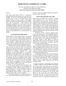
Figure 1: Layout of FLASH.
FLASH LINAC RF SYSTEM The FLASH linear accelerator is designed to accelerate electrons to energy up to 1 GeV. The current state is schematically presented in figure 1. The injector consists of a laser-driven photocathode in a 1.5-cell RF cavity operating at 1.3GHz with a peak accelerating field of 40MV/m on the cathode. The electron injector section is followed by a total of six 12.2m long accelerating modules (ACC) each containing eight 9-cell superconducting niobium cavities (During our experiment ACC6 wasn’t installed yet). For RF generation we are using 5MW klystrons for RF Gun, ACC1, ACC2 &ACC3, and a 10MW klystron for ACC4, ACC5 & ACC6 (figure 2). With the accelerated electrons a free electron laser will produce coherent, monochromatic light. The wavelength of the light depends on the energy of the accelerated electrons. It can be tuned between 6nm and 120nm. Successful operation of FLASH at a wavelength of 6.5nm has been achieved [3]. For 6.5nm radiation wavelength the accelerator provides beam energy of 986MeV.
Figure 2: FLASH RF System Diagram. Operation of RF stations at different repetition rates.
GOALS AND OPERATIONAL REQUIREMENTS Considerable experience of RF control at high gradients close to 30MV/m with pulsed RF and pulsed beam has T04 Accelerator/Storage Ring Control Systems
1523
TUPP001
Proceedings of EPAC08, Genoa, Italy
been gained at FLASH accelerator. The goal of the set-up presented here was to establish the possibility of operating the cavities with two gradient levels (pulse to pulse and intra pulse) so that they can be run at high gradient along with (during) SASE operation. This will allow for • gaining operating experience at high gradient over long periods of time, • the possibility of working on the second RF pulse during FEL runs (needs to be shown that we can do this without disrupting experimental program), • establishing 10 Hz operation with a 10MW klystron, • proving that SASE is not affected by the second ramp level, • looking at and compare amplitude and phase regulation within standard operation mode.
Operational Requirements The main operational requirement is to provide the possibility to operate the machine within alternating pulses without disturbing the user run. The second (high gradient) ramp must be set up so that making an adjustment to the lower (SASE) ramp does not affect the high gradient ramp. This is so that operators can adjust the level with beam without worry of tripping on the high gradient level.
BRIEF DESCRIPTION OF CONTROL ALGORITHM In the RF system for FLASH accelerator each klystron supplies RF power to up to 24 cavities. The FLASH RF control system [4] employs a completely digital feedback system to provide flexibility in the control algorithms, precise calibration of the accelerating field vector-sum, and extensive diagnostics and exception handling capabilities. The RF control algorithm is implemented in DSP (Digital Signal Processor) firmware and DOOCS (Distributed Object Oriented Control System) servers[5]. The digital feedback controls in-phase and quadrature component of the cavity field. High frequency probe signals are used to measure the accelerating field in the individual cavities. These 1.3 GHz signals are converted to 250 kHz and sampled by the ADCs with 1 MHz rate, i.e. two subsequent data points describe I and Q component of the cavity field. The samples are scaled and rotated to compensate the phase delay in the cable and calibrate the fields in the individual cavities. Then the sum of individual field vectors is calculated and rotated to adjust the loop phase. The vector sum is filtered by the low pass filter and the feedback algorithm applies the proportional gain to the regulating error values. A feed forward table is added to the value of the calculated control action. The real and imaginary parts of the calculated table are converted by the DACs separately and control the RF vector, applying the correction signal to the vector modulator.
06 Instrumentation, Controls, Feedback & Operational Aspects
1524
TECHICAL IMPLEMENTATION Timing events from FLASH accelerator are used to synchronize all accelerator subsystems and are managed by DOOCS timing server. Programmable timers are triggered by these events to generate the start pulses for the klystrons, DSPs or ADCs. A timer unit provides several independent output channels. Some machine parameters that change from macro pulse to macro pulse need to be delivered in time to run all digital feedback loops in parallel. The data words from the telegrams are stored in a dual port memory. This information is readable from the local connected computers. The machine was triggered by timing system with repetition rate 5Hz, except for last RF station with control system which was triggered by 10Hz (figure 2). The DSP server crates two reference set point and feed forward tables for alternate pulses. The actual tables are a superposition of both reference tables.
PERFORMANCE RESULTS Alternating Gradients from RF Pulse to RF Pulse Alternate RF pulses have different gradients on ACC4/5 and beam for SASE is accelerated at first RF pulse (figure 3). Gradients of second RF pulse are operated at high level. Both levels can be changed independently from each other. One can close/open feedback loop, change RF parameter such as phase of accelerating field, RF pulse flat-top duration etc. without any effects to first (SASE) RF pulse.
Figure 3: Alternating gradients from RF pulse to RF pulse.
Different Gradients Within RF Pulse Figure 4 shows the second RF pulse with two gradient levels. Beam is accelerated on first part and the gradient of second part operated at maximum level, close to 20 MV/m. Both levels can be adjusted independently from each other. The SASE levels with alternating RF pulses are shown in figure 5. The yellow indicates maximum, the green average and the blue actual levels. The alternating gradient operation does not degrade the SASE levels.
T04 Accelerator/Storage Ring Control Systems
Proceedings of EPAC08, Genoa, Italy
Figure 4: Different gradients within RF pulse. We also have operated the first pulse with beam, second pulse without beam and with two levels of gradients. The SASE level is the same as with one pulse mode operation, as well. Afterwards we switched off the first pulse for the alternating gradient scheme and put the beam pulse on the first low level flat top of two levels of RF pulse. We have observed the same level of SASE.
Figure 5: Alternate SASE performance (lower gradient ramp) with a high gradient ramp. SASE is not degraded and affected by this operation.
TUPP001
small or well damped for the switching from RF pulse to pulse without affecting SASE. • The control performance shows no degradation as compared to the simple 5Hz operation. Long term experience from operating these schemes in parallel to FEL user operation confirms such a time sliced operation does not affect the SASE process and the experimental program. • Proof for the XFEL timing proposal [6]. We are planning to continue operation of the machine with described scheme to gain experience with high gradient operation, learn trips and reliability issues, explore gradient level can operate with and without feedback. That will allow us to improve regulation, apply adaptive feed forward algorithm for both alternating pulses in parallel to fast feedback loops.
Figure 6: Control performance (amplitude and phase) for high alternating gradient.
REFERENCES Regulation The control performance for high alternating gradient is as good as for single pulse mode. In figure 6 is shown the case when gradients are close to 20MV/m. The feedback gain is 50. The control performance for high gradient part is the same as one pulse mode operation, except pulse length is shorter.
CONCLUSIONS The first long term tests of such accelerator operation schemes at FLASH, operating alternating RF gradients parallel to FEL user operation, look quite promising. Results for ILC and the European XFEL: • Long term high gradient tests (several weeks) showed no problems at 20 MV/m. Microphonic effects and mechanical oscillations are sufficiently
06 Instrumentation, Controls, Feedback & Operational Aspects
[1] “The Conceptual Design Report for the TESLA Test Facility”, Edited by D.A. Edwards, DESY, 1995 [2] “FLASH – Free Electron Laser in Hamburg”, DESY brochure, 2007 [3] S. Schreiber “Operation of FLASH at 6.5 nm Wavelength”, this conference, 2008 [4] V. Ayvazyan, A. Brandt, S. Choroba, G. Petrosyan, K. Rehlich, S. N. Simrock, P. Vetrov “RF Control System for The DESY FLASH Linear Accelerator”, EUROCON’07, Warsaw, Poland, 2007 [5] K. Rehlich “Status of the FLASH Free Electron Laser Control System”, ICALEPCS’07, Knoxville, Tennessee, USA, 2007 [6] E. Vogel, V. Ayvazyan, J. Becker, W. Kriens, K. Rehlich, S. Simrock, P. Tege “Timing requirements and proposal of a timing concept for the European XFEL”, DESY Report, TESLA-FEL 2006-13, 2006.
T04 Accelerator/Storage Ring Control Systems
1525