autostereoscopy) and secondly, at any angle of viewing a viewer sees the same image, i.e. the image does not rotate with the change of angle of view because ...
ALTERNATIVE APPROACH TO 3D DISPLAYING Oleg G. Semyonov State University of New York at Stony Brook, 214 Old Chemistry Building, Stony Brook 11794, USA A method for displaying volumetric images, which exploits our binocular vision and does not require eyewear, is discussed. The display can be rendered as a matrix of pivoting micromirrors irradiated by a light beam; each micromirror focuses its pixel beams to the same point of displayed volumetric image. 3D perception of image can be achieved by scanning the point of beams intersection over a virtual surface of displayed image in space. OSIS Codes: 120.2040; 110.6880
1. Introduction
The dream about a device generating optical volumetric replicas of real objects, just as we see them by eyes, persisted over centuries and recently found its second wind after invention of video imagers and image processors. Image processing has already become a huge scientific area where thousand researchers are actively working. The engineering efforts are mostly concentrated on the ‘old good’ two-dimensional imaging however a growing team of engineers in three-dimensional (3D) vision area is also working actively. The current “demand for 3D stems more from whim then necessity, which makes it difficult to gauge exactly what kind of image is sought” 1 to be preferable for a potential customer, however the likewise whim seemed to drive, in its time, the engineers toward the prominent progress in automobile industry and, recently, toward the boom in the cellular phones with cameras. A variety of 3D stereo-displays and quasi-volumetric imagers has been proposed and some have already appeared on the market. Nonetheless, the common vision is a display round with people, each seeing what they would see if they were looking at a solid object instead of an image. Virtually all the tricks for achieving 3D-perception of images, from paintings to modern stereo movies and displays, are based on optical illusion. 2D-images on a flat surface are either distorted in accordance with the rules of perspective to produce the perception of depth, or consist of two images separately for right and left eyes to create a stereo effect. While visual art such as photography and cinematography uses perspective
2
together with 1
light and shade play, interposition, aerial perspective (blurring of distant objects as if they were in haze), textual gradient, and motion parallax,
3
leaving the rest to our imagination in
perceiving the depth, stereoscopy mimics, in addition to all the tricks above, our binocular vision to actually see the depth by forcing our brain to arrange the objects of a flat image as if they were hovering in 3D space. However, despite the prominent eye-catching effect of stereoscopy and the persistent efforts to promote the stereoscopic systems, they have not found a proper recognition in mass production so far. There are two reasons for this slow advance: firstly, the stereoscopic systems are costly in comparison with the conventional 2D systems and secondly, they need a kind of eyewear to watch stereoscopic images: on a colormultimplexed (anaglyph) display that creates images of different colors for left and right eyes, on a polarization-multiplexed display producing images of mutually perpendicular polarization, or on a time-multiplexed display where the left and right views are sequentially shown. The recently appeared autostereoscopic displays
1, 4
require no eyewear; the views are
spatially multiplexed on a pixel-addressable screen and then separated by an optical layer which sends the left view and the right view at different angles to be perceived by left and right eyes separately. All stereoscopic methods are suffering from two drawbacks: firstly, the angle of viewing is limited (as well as the distance to the screen in the case of autostereoscopy) and secondly, at any angle of viewing a viewer sees the same image, i.e. the image does not rotate with the change of angle of view because the viewer sees actually through the viewpoints of the cameras. One of the first truly volumetric imagers was developed by NASA.
5
The image
capabilities of the system stem from the technique that uses a laser-light projection apparatus and a rotating "vortex" screen to create a "viewing box." The system displays nearly 34 million "voxels" (i.e., x, y, and z points corresponding to the pixels of a 2-D image) of data, enabling a user to view a 3-D shape from multiple perspectives without the need for special viewing aids or goggles. The information about another system generating the real spatial image with 360º view angle was published in 2002
6
and 2004.
7
The system is based on a
rotating screen, where a sequence of 5940 2-D images from a XGA-resolution light modulator is projected. This combination of hardware and software generates 3D volumetric images inside a vacuumed transparent spherical dome, which can be seen from a full 360 degrees without goggles. Nevertheless, this masterpiece of optomechanics is far from mass production and out of reach of ordinary consumers. Our dream is about something like communication devices shown in sci-fi movies, where a 3D image is hovering in air without screens or scattering media being observed from any direction without goggles or other eyewear. A possible approach to displaying the volumetric 2
images which can be seen as hovering in space without reflecting screens or light scattering fog and which can be observed without eyewear is outlined below.
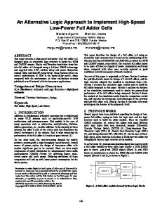
2. Perception of image Our binocular vision is based on the separate perception of light beams emitted by an object at different angles. We see an illuminated object when it scatters light emitted from natural or artificial sources and every point on the object’s surface radiates the scattered light more or less isotropically. An eye catches a fraction of scattered light from a particular point D2, where A is the area of pupil
on the surface within a solid angle of vision-by-
and D is the distance to the object (Fig. 1). The object is seen slightly different by left and right eyes, because our eyes see the object from different angles: the closer is the object, the lager is the stereo-angle
= 2arctg(d/2D), where d is the distance between the eyes, and the larger is disparity between the images on the retinas of left and right eyes. To obtain a volumetric replica of a real object,
D
which can be perceived as a real object, an optical system and/or a multiplexing display is supposed to create a 3D-image in space, which imitates the real
d
object in the sense that every point of image radiates a divergent quasi-isotropic fan of rays having
Fig.1. Binocular vision (see details in the text) of 3D-byeye cone of a point on the surface of objects, D is the distance between observer and object, d is distance
intensity that mimics the intensity distribution of
the stereo-angle.
produced by a properly designed optical system. For
scattered light on the surface of a real object. In principle, such the volumetric image can be
example,
an
optical
toy
“Mirage”
(Edmund
Scientific) consisting of two spherical mirrors creates the object’s ‘apparition’ in air above the toy, which looks indistinguishable from the real object placed near the surface of the bottom mirror. As seen from Fig. 2, the system of mirrors transforms each luminous point of the object’s surface to the conjugative point on the virtual ‘surface’ of the volumetric image located above the upper mirror; the image is rotated by 180º with respect to the real object but conserves its 3D perception when viewed by eyes. A viewer sees the volumetric image because his binocular vision works the same way as it would be if a real object were placed instead of image. One can walk around and watch the image from any side. The ‘mirage’ effect is achieved because: a) every virtual point of the image is created by the bottom mirror 3
as a converging-in-space fan of rays originated from different points on the mirror surface and, therefore, every point of this image emits outside a divergent fan of rays the same way as if a real object was placed instead of the image and b) left and right eyes of a viewer capture the rays emitted by a particular point of image from two different solid angles of visibility-bycorresponding areas S on the surface of the bottom mirror located on the lines of sight (shown by the dashed lines in Fig. 2): S = r2
2
/D2 , where r is the distance between the
viewed point of the image and the surface of the mirror along the line of sight and D is the distance between the eye and the observed point
Mirage
of image. The important feature is that one can see image only when the light-reflecting portion
r
of surface of the bottom mirror and the corresponding point of image, where the rays are
S
focused to, lie on the line of sight; it is Object Fig.2. Optical diagram of Mirage toy with the ray paths traced for a couple of rays emitted from a point on the surface of a real object located on the bottom mirror. Here r is the distance between a point on the surface of bottom mirror, where a ray is reflected, and a corresponding point on the image surface, S is the area of bottom mirror participating in perception of a is the visibility-by-eye angle (dashed lines) of this point.
impossible to see image when the line of sight is inclined above the edge of bottom mirror and therefore it is impossible to see other objects of real world through the mirage image as it is often shown in sci-fi movies. Nevertheless, the idea
looks
attractive
for
application
in
optoelectronic displaying.
Imagine a matrix of light-emitting pixels on a spherical surface installed instead of the bottom mirror in Fig. 2 (it can be a matrix of laser diodes or a matrix of micro-mirrors irradiated by a light source), which can be controllably tilted to direct every pixel microbeam in any direction within the desired angle of visibility determined by the display’s size, the distance between viewer and display, and the size of image we intend to create. Suppose all pixel beams can be directed to one and the same point in space and that every pixel beam can be focused, if necessary, on this point to produce a point of a spatial image (Fig. 3a). There is no need for mirrors or other additional optics and there is no need for a real object; nonetheless, such the point will be perceived by a viewer as a luminous point located in space being visible when the viewer is in the angle of visibility
o
because the point radiates
a divergent fan of rays as if it belong to a real object.
4
dp i
R
v o v ob
a)
b)
Fig.3. a) Displaying a virtual image of a point in space by a spherical display made of pivoting light-emitting pixels focused on this point; b) displaying a virtual volumetric image of an object: 0 is the solid angle of visibility where a given point can be observed, R is the distance between a current point of beams crossing and an emitting pixel having size dp i ~ dp v is the total angle of observed from any direction around a horizontal display.
The rest looks obvious. What is needed is to scan the point of crossing of all pixel beams over the virtual volumetric surface of image, we intend to display, or, more exactly, to scan it over a portion of virtual surface of image on its far side from the origin of a given pixel beam on the display surface (i.e., over a corresponding nearest side of this virtual image with respect to a viewer) within a desired solid angle of visibility. The scans can be rendered analogous to TV-scanning, where the frames are made of horizontal scan lines. To avoid flickering, this scanning must be sufficiently fast, say, 30 to 60 frames per second. The ‘apparition’ will be perceived volumetrically such as the image of the Mirage toy because, like in the case of a real object, every point of this virtual image emits the divergent quasiisotropic fan of rays into the visibility angle and our binocular vision works as usual. No image is generated on the display itself; information about the current positions of virtual points of image (about every point of crossing of beams in space) together with the intensities of particular beams at a particular moment and the perceived color can be multiplexed as a time sequenced stream of data addressed to every beam-generating pixel. Ideally, every pixel has to be addressed individually to direct the intensity- multiplexed pixel beams to a current scan point of volumetric image. The image can be viewed from different sides and a 360 degrees view can be achieved if the display is positioned horizontally (Fig. 3b). In the last case, the image is visible when the viewing angle angle of visibility
v is less then the total
and the elevation angle of observation ob exceeds the elevation angle
of visibility v.
5
In a real system, the distortions of pixel beams would blur the image. In particular, the image quality can be influenced by inaccuracy of pixel beams alignment, optical diffraction, beam divergence, and optical aberrations. Diffraction. Focusing of pixel beams is preferable when the angle of diffraction of a pixel beam diff =
p
is less then the focusing angle i = dp/R, i.e. if R < dp
2
, where R
(approximately equal to the focal distance F if focusing is produced by each properly formed reflection pixel) provided other factors, such as optical aberrations, are negligible. The halfwidth of image’s spot, which is the point of crossing of pixel beams on the condition of ideal alignment, can be estimated as ds
p
(for example, ds
mm, if R = 10 s(R)
(resolution
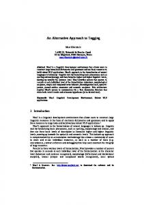
due to diffraction versus distance from the display surface) are shown in Fig. 4 for various 2
optical sizes of pixels dp. Focusing of pixel beams becomes useless when R > dp ds, 0.09
.
cm
0.08 0.07 0.06 0.05 0.04 0.03 0.02 0.01 0 0
20
40
60
80
R, cm Fig.4. Diffraction spot ds
p = 100 (bottom line). Solid circles on the lines indicate the distance R eq at which the diffraction spot diameter is equal to pixel size. Additional focusing of pixel beams is advantageous for better resolution if R < Req and useless otherwise.
Divergence. In addition to diffraction, the pixel beams will be more or less divergent by the nature of the real sources of electromagnetic waves (e.g., laser beams consisting of multiple angular modes or light beams formed by optical systems when emitters of finite size are used), so the wave-fronts of pixel beams will never be absolutely flat or precisely spherical. If no focusing is implemented, the cross-sections db of unfocused beams at a distance R will
6
be the functions of their divergence half-angle multimode commercial lasers distance R taken 2
0.3dp/2
b=
dp + 2
. Since the divergence of
is ~ 10-3 radians, the images must be generated at the
, if the tolerable increase of cross-section of unfocused beams is
0.3dp. In the case of focused pixel
beams, the caustic size in the focal plane
dc =
, where F
image are limited by the condition R
dc0/2
to obtain the desired resolution
dc0
= 10-3 when dc0
(caustic size), for example R
Optical aberrations. When the pixel beams are focused by a sort of optical system, optical aberrations can also worsen the resolution. Approximation of paraxial optics is valid for the small focusing angles
i =
dp/F,
when
dp