Stremler, Communication Systems. • Chapter 5.1-5.2, 5.4 - 5.5. Introduction. The
purpose of a communication system is to transmit information-bearing signals or
...
Amplitude Modulation Reference – Stremler, Communication Systems • Chapter 5.1-5.2, 5.4 - 5.5 Introduction The purpose of a communication system is to transmit information-bearing signals or baseband signals through a communication channel separating the transmitter from the receiver.
E.1
Baseband signal The term baseband is used to designate the band of frequencies representing the original signal as delivered by a source of information
Baseband signals e.g. voice, data, video
Modulator Transmitter
E.2
The proper utilization of the communication channel requires a shift of the range of baseband frequencies into other frequency ranges suitable for transmission, and a corresponding shift back to the original frequencies after reception.
ω
ω
ω
E.3
Modulation Modulation is a process by which a parameter (e.g. amplitude or frequency) of a signal (called carrier signal) is varied in proportional to a second signal (called modulating signal). Generally, the frequency of the carrier signal is much higher than the frequencies of the modulating signal.
Modulating signal
Carrier signal E.4
Example 1 Amplitude of the modulated signal is proportional to the modulating signal If the modulating signal and carrier are f(t) and Bcos(ωct), respectively, the amplitude modulated signal is f(t) * Bcos(ω ct). If f(t) = Acos(ωmt) , the signal becomes Acos(ωmt) * Bcos(ω ct) = AB/2 *[ cos(ω c +ωm)t + cos(ω c -ωm)t]
The frequency is shifted from ωm to ω c +ωm and ω c - ωm E.5
Purposes of Amplitude Modulation – The use of amplitude modulation may be advantageous whenever a shift in the frequency components of a given signal is desired. Ease of radiation: Transmitting a voice signal through space via electromagnetic waves. – If the maximum voice frequency is 3 kHz, the minimum wavelength is 100km (wavelength = velocity of light / frequency). Because antennas with dimensions less than one-quarter wavelength are inefficient, it is a advantage to raise the frequency to at least tens of MHz before E.6 transmission. (At 30MHz, wavelength = 10m)
Multiplexing: – By proper choices, a large number of signals can be transmitted at the same time without mutual interference. Commercial radio are assigned different frequencies for different stations.
E.7
Type of modulation Analogue Modulations: Amplitude Modulation Frequency Modulation Phase Modulation Digital Modulations Factors for consideration: Generation: bandwidth and Power Reception (Detection): Performance S/N ratio, error rate E.8
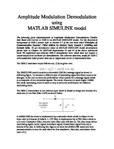
Amplitude Modulation: Double Sideband Suppressed Carrier (DSB-SC) Modualtion Consider a sinusoidal carrier c(t) defined by c(t ) = Ac cos ω ct where Ac is the carrier amplitude and fc is the carrier frequency (ωc=2πfc). Let f(t) denote the baseband signal that carries the specification of the message. The DSB-SC modulated signal is f DSB − SC (t ) = f (t ) ⋅ c(t )
= f (t ) cos ω ct
let Ac = 1 E.9
Applying the modulation property of the Fourier transform, the spectral density of f DSB− SC (t ) is FDSB − SC (ω ) =
t
t ω
f DSB− SC (t ) f (t ) − f (t )
c(t )
f (t ) W
1 1 F (ω + ω c ) + F (ω − ω c ) 2 2
t 2W
− ωc
ωc ω
− ωc
ωc ω E.10
Amplitude modulation translates the frequency spectrum of a signal by ± ω c but leaves the spectral shape unchanged. The bandwidth of f DSB− SC (t ) is 2W. (The bandwidth of f(t) is W) The spectral content for positive frequency above ωc is called the upper sideband (USB) of f DSB− SC (t ) and the spectral content for positive frequency below ωc is called the lower sideband (LSB) of f DSB− SC (t ).
LSB
2W
USB
ωc ω
− ωc
E.11
Demodulation The DSB-SC signal can be demodulated by multiplying cos ω c t to the signal. f DSB − SC (t ) ⋅ cos ω c t = [ f (t ) cos ω c t ] ⋅ cos ω c t = f (t ) cos 2 ω c t =
1 1 f (t ) + f (t ) cos 2ω c t 2 2 1 1 Q cos 2 x = + cos 2 x 2 2
The Fourier transform of the output is
1 1 ℑ{ f DSB − SC (t ) ⋅ cos ω c t} = ℑ f (t ) + f (t ) cos 2ω c t 2 2 1 1 1 = F (ω ) + F (ω + 2ω c ) + F (ω − 2ω c ) 2 4 4 E.12
A lowpass filter is required to extract the signal f(t). f DSB − SC (t )
2W
− ωc
t
ωc ω f DSB − SC (t ) ⋅ cos ω c t
− 2ω c
2ω c
ω
E.13
Generation of DSB-SC signals A signal spectrum can be translated an amount ± ω c by multiplying the signal with any periodic signal whose fundamental frequency is ω c . • Therefore, a DSB-SC can be generated by multiplying the signal with any periodic signal.
E.14
Example Any periodic power signal can be represented can be ∞ represented by the Fourier series, jnω t p(t ) =
∑Pe
n = −∞
n
o
Choose ωo= ωc and multiplying p(t) with f(t) gives f (t ) p(t ) =
∞
∑ P f (t )e
n = −∞
n
jnω o t
∞ ⇒ ℑ{ f (t ) p(t )} = ℑ ∑ Pn f (t )e jnω ot n = −∞ ⇒ ℑ{ f (t ) p(t )} =
∑ P ℑ{f (t )e ∞
n
n = −∞
⇒ ℑ{ f (t ) p(t )} =
jnω o t
∞
∑ P F (ω − nω n
n = −∞
o
} {
}
Q ℑ f (t )e jω ot = F (ω − ω o )
)
E.15
The spectrum of f (t ) p (t ) contains F (ω ) and F (ω ) translated by ± ω c ,±2ω c ,±3ω c ,.... f (t )
F (ω )
t
p(t ) f (t )
ω
ℑ{ f (t ) p(t )} p(t )
− ωc
Pn
− ωc
ωc
2ω c
ωc
2ω c ω
ω E.16
DSB-SC signal can be obtained by applying the signal to a bandpass filter. The bandpass filter allows those frequency components centered at ± ω c to pass and attenuates all other frequency components. f DSB− SC (t )
ω p(t ) f (t ) BPF
ωc
− f (t )
t
ℑ{ f (t ) p(t )} − ωc
f (t )
2ω c ω
E.17
Since the frequency of the modulated signal is different from the input signal frequency and the carrier signal frequency, systems that are either time-varying or nonlinear must be used. Example:diodes are used as switches to mix the modulating signal and carrier signal
f (t )
BPF
cos ω ct These diodes alternately switch the filter input between the input signal and ground at the carrier frequency. E.18
Amplitude Modulation: Large carrier (DSB-LC)
To demodulate a DSB-SC modulated signal (f (t ) cos ω c t ), a local oscillator is needed to generate a signal which is identical to the carrier signal (cos ω c t). If there are a small frequency error ( ∆ω ) and a phase error ( θ ), the demodulated signal becomes
1 2 f (t ) cos[∆ω + θ ]
.
E.19
Case I
∆ω = 0 θ ≠ 0
The demodulated signal is 1 2 f (t ) cos[θ ]. The phase error causes a variable gain factor in the output signal. For small fixed phase errors, this is quite tolerable. For phase error approaching ± 90° , the received signal is wiped out. In some cases, the phase error varies randomly, resulting in unacceptable performance
E.20
Case II ∆ω ≠ 0 θ = 0 The demodulated signal is 1 2 f (t ) cos[∆ωt ]. We obtain the signal f(t) multiplied by a low frequency sinusoid. This is unacceptable. To demodulate a DSB-SC signal, an synchronized oscillator, which requires complicated circuitry, is needed. To reduce the complexity of the receiver, carrier signal is also transmitted.
E.21
AM
Consider a sinusoidal carrier c(t) defined by c(t ) = cos ω c t . Let f(t) denotes the baseband signal that carries the message. The AM (DSB-LC) signal is f AM (t ) = f (t ) ⋅ c(t ) + Ac(t ) = f (t ) cos ω c t + A cos ω c t
The spectral density of f AM (t ) is 1 1 F (ω + ω c ) + F (ω − ω c ) 2 2 + πAδ (ω + ω c ) + πAδ (ω − ω c )
FAM (ω ) =
E.22
.
c(t )
f (t ) F (ω ) W
f DSB− SC (t )
t t
t
ω f (t ) + A f AM (t )
FAM (ω )
− ωc
2W
ωc ω E.23
Envelope Detection
The AM signal can be rewritten as f AM (t ) = [ f (t ) + A]cos ω c.t The amplitude of the signal is f (t ) + A . If A is large enough, the envelope of the modulated signal will be proportional to f(t). Therefore, the AM signal can be demodulated using a envelope detector. Example Consider a single frequency sinusoidal signal cosωmt, the AM signal becomes f AM (t ) = A[1 + m cos ω mt ]cos ω c t where m=
Peak DSB − SC amplitude Peak carrier amplitude E.24
m < 1 f AM (t ) = [1 + 0.5 cos ω mt ]cos10ω mt
m=1
f AM (t ) = [1 + cos ω mt ]cos10ω mt
E.25
m>1
f AM (t ) = [1 + 2 cos ω mt ]cos10ω mt
In general, if A ≥ min{ f (t )} , the AM signal can be demodulated using a envelope detector. m is also called modulation index. E.26
Carrier and sideband power
In AM signal, the carrier term does not contain any information about the modulating signal f(t). Therefore the power expended in this carrier is wasted for transfer of information. – For a 1Ω load, the average power of AM signal ( f (t ) cos ω c t + A cos ω c t ) is 2 f AM (t ) = f 2 (t ) cos 2 ω c t + A2 cos 2 ω c t + 2 A f (t ) cos ω c t
where the bar indicates time average. We assume that f(t) varies slowly with respect to cosωct and the average value of f(t) is zero, then the last term is zero so that E.27
2 f AM (t ) = f 2 (t ) cos 2 ω c t + A2 cos 2 ω c t
=
A2 1 2 f (t ) + 2 2
E.28
Detection of AM signals
Envelope detector Any circuit whose output follows the envelope of the input signal will serve as an envelope detector. The simplest form of an envelope detector is a nonlinear charging circuit with a fast charge time and a slow discharge time.
≈ f (t )
f AM (t )
C
R f AM (t )
E.29
Limitation The AM is limited to applications which do not require a frequency response down to zero frequency because the adding of carrier signal will ruin the low frequency signals. Example voice signal
E.30
Single-sideband (SSB) modulation
Introduction – The major disadvantage of DSB modulation is the doubling of the bandwidth. – For any real-valued signal, we have F (−ω ) = F * (ω ) *
∞ ∞ Q F (−ω ) = ∫ f (t )e jωt dt = ∫ f (t )e − jωt dt = F * (ω ) −∞ −∞
– After multiplication by a sinusoid at ω c , half of this spectral density is translated up in frequency and centered about ω c and half is translated down to − ω c . E.31
– The positive frequency content in F (ω ) becomes the upper sideband for ω c > 0 and the lower sideband for ω c < 0 . The negative frequency content becomes the lower siderband for ω c > 0 and the upper sideband for .ω c < 0 – Each pair of sidebands contains the complete information of the original signal. DSB-SC
USB
LSB
− ωc
LSB
USB
ωc E.32
Therefore the original signal can be recovered from either the upper or lower pair of sidebands. F (ω ) FDSB − SC (ω ) =
1 1 F (ω + ω c ) + F (ω − ω c ) USB LSB 2 2
FSSB − (ω )
LSB
− ωc
LSB
ωc
USB
LSB USB
ωc − ωc Bandpass filter FSSB (ω ) USB
− ωc
+
ωc
Frequency shifting E.33
– A SSB signal can be generated by suppressing one of the sideband of a DSB signal. However, the filter must have a very shape cutoff characteristic at ω c . – If the bandwidth of the signal is narrow, SSB signal can be generated using phase-shift method. (refer to textbook)
E.34
Vestigial-sideband (VSB) Modulation
Introduction – The generation of SSB signals may be difficult when the modulating signal bandwidth is wide or where one cannot disregard the low-frequency components. – To conserve spectrum space, a compromise is make between SSB and DSB -- VSB (Vestigial Sideband) Modulation. – In VSB, only a portion of one sideband is transmitted.
E.35
SSB +
− ωc
ωc VSB − ωc
ωc
− ωc
ωc
Using a filter H V (ω ) , a VSB signal can be generated from a DSB signal 1 1 FVSB (ω ) = F (ω + ω c ) + F (ω − ω c ) H V (ω ) 2
W
DSB
ωc
W
W
ωc
2
VSB
H V (ω )
W
ωc E.36
To demodulate the VSB signal, synchronous detector (frequency shifting plus filtering) can be used. The demodulated signal is Eo (ω ) = 1 / 2[F (ω ) H V (ω + ω c ) + F (ω ) H V (ω − ω c )]
− ωc
FVSB (ω ) =
ωc
1 F (ω ) H V (ω + ω c ) 2
Eo (ω ) =
1 1 F (ω + ω c ) H V (ω ) + F (ω − ω c ) H V (ω ) 2 2
1 F (ω ) H V (ω − ω c ) 2
1 1 F (ω ) H V (ω + ω c ) + F (ω ) H V (ω − ω c ) 2 2
E.37
– To obtain the last diagram, the filter must satisfy the following condition: [HV (ω + ω c ) + HV (ω − ω c )]LP = constant ω