AN-1065. APPLICATION NOTE. OneTechnology Way •P.O. Box 9106 •Norwood,
MA .... to normal sample mode, the result is 0.07 mV rms, as shown in. Figure 6.
AN-1065 APPLICATION NOTE One Technology Way • P.O. Box 9106 • Norwood, MA 02062-9106, U.S.A. • Tel: 781.329.4700 • Fax: 781.461.3113 • www.analog.com
Configuring the AD5420 for HART Communication Compliance by Maurice Egan
INTRODUCTION
IMPLEMENTATION
For many years, 4 mA to 20 mA communications have been used in process control instrumentation. The 4 mA to 20 mA communications method is reliable and robust, and offers high immunity to environmental interference over long communication distances.
The AD5420 is a 16-bit, digital to 4 mA to 20 mA converter with inputs to accommodate the output of a HART modem. The output of the AD5700 HART modem is attenuated and ac coupled at the CAP2 pin of the AD5420; this results in the modem output being modulated on top of the 4 mA to 20 mA analog current without affecting the dc level of the current.
The disadvantage of 4 mA to 20 mA communication is that it is a one-way communication and can only transmit one process variable, which in modern industrial control systems is a limitation.
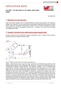
The circuit in Figure 1 shows how the AD5420 can be interfaced with a microcontroller and the AD5700 HART modem to construct a HART capable 4 mA to 20 mA current output, typical of PLC and DCS systems.
The development of the highway addressable remote transducer (HART®) standard opened up new possibilities for 4 mA to 20 mA communication. HART is a digital two-way communication that is compatible with 4 mA to 20 mA current loops. A 1 mA peakto-peak frequency shift keyed (FSK) signal is modulated on top of the 4 mA to 20 mA analog current signal. The two frequencies used are 1200 Hz representing Logic 1 and 2200 Hz representing Logic 0, based on the BELL 202 communications standard.
10.8V TO 60V
2.7V TO 5.5V 10µF
10µF
0.1µF
0.1µF 10kΩ
DVDD
AVDD C3
CAP1
DVCC FAULT
0.1µF
AVDD REFIN 0.1µF
CLEAR
HOST CONTROLLER SUCH AS ADuC7060
10µF
REFOUT LATCH SCLK SDIN
UART INTERFACE
IOUT
SDO
AD5420 CAP2
GND
4mA TO 20mA CURRENT LOOP RL 500Ω
0.1µF C2
C1
AVDD TXD RXD
VCC HART_OUT
RTS CD
REF 1µF
XTAL1
1.2MΩ
XTAL2 ADC_IP AGND DGND
1.2MΩ
300pF
150kΩ 150pF
8.2pF
08875-001
8.2pF
AD5700
3.6864MHz
Figure 1. AD5420 in HART-Enabled Circuit
Rev. A | Page 1 of 4
AN-1065
Application Note Using Equation 1 and Equation 2, one can determine that
DETERMINING THE VALUES OF C1 AND C2 There are three unvalued capacitors shown in the circuit in Figure 1: C1, C2, and C3. C1 and C2 determine the scaling and coupling of the HART modem output to the AD5420 input. C3 is discussed later. The output of the modem is a FSK signal consisting of 1200 Hz and 2200 Hz shift frequencies. This signal must translate to a 1 mA peak-to-peak current signal. To achieve a 1 mA peak-to-peak current, the signal amplitude at the CAP2 pin must be 48 mV peak-to-peak. Assuming that the modem output amplitude is 500 mV peak-to-peak, its output must be attenuated by 500/48 = 10.42. The values of the C1 and C2 capacitors can be expressed as follows:
C1 = 1.85 nF C2 = 17.45 nF
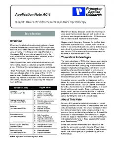
These values are theoretical, and approximate values with a similar ratio work equally as well, since the amplitude of the HART signal received across a 500 Ω load can be within the range of 400 mV p-p to 600mV p-p. The following measurements were made with values C1 = 2.2 nF and C2 = 22 nF. Figure 3 shows the individual 1200 Hz and 2200 Hz shift frequencies measured across a 500 Ω load resistor. The waveforms have amplitudes of approximately 500 mV p-p. TEK RUN 250kS/s
SAMPLE
C1 + C2 = 10.42 C1
C1 FREQ 1.2kHz
From this equation
C1 AMPL 496mV
(1)
REF1 FREQ 2.20264kHz
REF1
In determining the absolute values of the capacitors, ensure that the FSK output from the modem is passed undistorted. Thus, the bandwidth presented to the modem output signal must pass 1200 Hz and 2200 Hz frequencies. C1 C2 CAP1
CAP2
AVDD
FSK SIGNAL FROM MODEM
CH1 100mV REF1 100mV
R1 R2 12.5kΩ
RSET
08875-002
IOUT
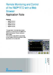
Figure 2. View of AD5420 Internal Circuitry
Note that in Figure 2 the external capacitors, C1 and C2, along with R1 and R2 form a high-pass filter with a cut-off frequency of
1 FC = 2 × π × (R1 + R2 ) × (C1 + C2) Choosing a high pass cut-off frequency of 500 Hz
C1 + C2 =
1 = 19.3 nF 2 × π × (4 kΩ + 12.5 kΩ) × 500
CH1
132mV
HART COMPLIANCE BOOST
DAC
M200µs 200µs
Figure 3. 1200 Hz and 2200 Hz Waveforms Measured Across a 500 Ω Load
AVDD
40Ω
4kΩ
REF1 AMPL 504mV
08875-003
C2 = 9.42 C1
(2)
For the circuit in Figure 1 to be HART compliant, it must meet the HART physical layer specifications. There are numerous physical layer specifications included in the HART specification documents; however, with regard to the AD5420, the two specifications that are most important are output noise during silence and analog rate of change.
Output Noise During Silence When a HART device is not transmitting (silent), it should not couple noise onto the network in the HART extended frequency band. Excessive noise may interfere with reception of HART signals by the device itself or other devices on the network. The voltage noise measured across a 500 Ω load must contain no more than 2.2 mV rms of combined broadband and correlated noise in the extended frequency band. The noise is measured with the circuit shown in Figure 4. The circuit includes a HCF_TOOL-31 filter available from the HART Communication Foundation. The loop current is set at 12 mA. No discernable differences in noise were measured with other current values.
Rev. A | Page 2 of 4
Application Note
AN-1065 3.3V
24V 10µF
10µF
0.1µF
0.1µF
10kΩ DVCC
CAP1
FAULT
AVDD REFIN 0.1µF
CLEAR REFOUT LATCH SCLK SDIN IOUT
SDO
AD5420 CAP2
AGND DIGITAL TEST FILTER HCF_TOOL-31
OSCILLOSCOPE OR TRUE RMS METER
08875-004
500Ω
Figure 4. Measuring Noise During Silence
As a means of supporting this measurement, the noise was also measured using an Agilent 3458A true rms meter where the measurement result was 0.085 mV rms, much less than the oscilloscope measurement. However, if the oscilloscope is set to normal sample mode, the result is 0.07 mV rms, as shown in Figure 6. The worst-case measurement of 0.4128 mV is well below the requirement of 2.2 mV rms. TEK RUN 250S/s
SAMPLE
C1 RMS 700µV
1
Pk DETECT CH1 2.00mV
400µV
Figure 5. Noise at Output of HART Filter, Oscilloscope in Peak Detect Mode
08875-005
CH1
CH1
400µV
Analog Rate of Change
1
M100ms
M100ms
Figure 6. Noise at Output of HART Filter, Oscilloscope in Sample Mode
C1 RMS 4.128mV
CH1 2mV
TEK RUN 500S/s
08875-006
Figure 5 shows the noise measured using the peak detect feature of a digital oscilloscope. The measurement displayed is 4.128 mV rms. The digital test filter has a gain of 10, thus, this measurement should be divided by 10 to give a measurement result of 0.4128 mV rms.
This specification ensures that when a device regulates current, the maximum rate of change of analog current does not interfere with HART communications. Step changes in current disrupt HART signalling. The test circuit is shown in Figure 4. For this test, the AD5420 is programmed to output a cyclic waveform switching from 4 mA to 20 mA with no delay at either value to ensure the maximum rate of change. To meet the HART specifications, the waveform at the output of the filter must not exhibit a peak voltage greater than 150 mV. Meeting this requirement ensures that the maximum bandwidth of the analog signalling is within the specified dc to 25 Hz frequency band.
Rev. A | Page 3 of 4
AN-1065
Application Note
The natural time for the output of the AD5420 to change from 4 mA to 20 mA is about 10 μs. This is obviously too fast and would cause major disruption to a HART network. To reduce the rate of change, the AD5420 employs two features: connecting capacitors at the CAP1 and CAP2 pins and a digital slew rate control function (Refer to the AD5420 data sheet for details).
Figure 7 shows the output of the AD5420 and the output of the HART filter. The peak voltage at the output of the filter is within specification at 91 mV. The slew rate control settings are SR CLOCK = 3 and SR STEP = 2, setting the transition time from 4 mA to 20 mA at 120 ms, C1 = 2.2 nF and C2 = 22 nF, and C3 is unconnected. If this rate of change is too slow, the slew time can be reduced; however, this will have the effect of increasing the peak voltage at the output of the filter. To counteract this, a capacitor (C3) can be connected from the CAP1 pin to AVDD as shown in Figure 1.
SAMPLE
C1 MAX 101mV C1 MIN –101mV
1
3
CH1 50mV CH3 2mV
M10ms
CH3
08875-008
It would require very large capacitor values connected at CAP1 and CAP2 to reduce the bandwidth below 25 Hz; therefore, the optimum solution is to use a combination of both connecting capacitors and enabling the digital slew rate control function of the AD5420. The two capacitors, C1 and C2, that attenuate and ac couple the HART signal to the AD5420 have the effect of reducing the rate of change of the analog signal, but not sufficiently to meet the specification. Enabling the slew rate control feature offers the flexibility to set the rate of change.
TEK RUN 5kS/s
6.84V
Figure 8. AD5420 and HART Filter Output Signals, SR CLOCK = 0, SR STEP = 3, C1 = 2.2 nF, C2 = 22 nF, C3 = 2.2 μF TEK RUN 2.5kS/s
SAMPLE
C1 MAX 28.6mV C1 MIN –23mV
1
CH1 10mV CH3 2V
C1 MIN –91mV
M20ms
CH3
6.84V
08875-009
3
C1 MAX 91mV
Figure 9. AD5420 and HART Filter Output Signals, SR CLOCK = 2, SR STEP = 2, C1 = 2.2 nF, C2 = 22 nF, C3 = 2.2 μF
1
The slew rate of the analog signaling can be set at the desired level through a combination of selecting the values of the C1, C2, and C3 capacitors and programming the digital slew rate control of the AD5420. CH1 50mV CH3 2V
M20ms
CH3
6.84V
08875-007
3
Figure 7. AD5420 and HART Filter Output Signals, SR CLOCK = 3, SR STEP = 2, C1 = 2.2 nF, C2 = 22 nF
Figure 8 shows the results of inserting a 2.2 uF capacitor for C3 and configuring the slew rate control with SR CLOCK = 0 and SR STEP = 3. The slew time for a 4 mA to 20 mA step takes approximately 30 ms. The peak amplitude at the output of the filter can be reduced further by increasing the value of C3, configuring a slower slew rate, or a combination of both as shown in Figure 9 where SR CLOCK = 2, SR STEP = 2 and C3 = 2.2 μF. This results in a 100 ms slew time and voltage peaks at the filter output of 28 mV.
LEARN MORE An alternative method of connecting the AD5420 and the AD5700 HART modem together can be found in the Circuit Note CN-0270. While this alternative solution requires the use of an external RSET resistor, it provides better power supply rejection performance than the CAP2 coupling solution described in this application note. The use of either solution results in the AD5700 HART modem output modulating the 4 mA to 20 mA analog current without affecting the dc level of the current.
©2010–2012 Analog Devices, Inc. All rights reserved. Trademarks and registered trademarks are the property of their respective owners. AN08875-0-4/12(A)
Rev. A | Page 4 of 4