AbstractâIn this communication, a new three-dimensional (3-D) dis- crete cosine transform (DCT) coder for medical images is presented. In the proposed ...
IEEE TRANSACTIONS ON INFORMATION TECHNOLOGY IN BIOMEDICINE, VOL. 4, NO. 3, SEPTEMBER 2000
259
Communications______________________________________________________________________ An Adaptive 3-D Discrete Cosine Transform Coder for Medical Image Compression Shen-Chuan Tai, Yung-Gi Wu, and Chang-Wei Lin
Abstract—In this communication, a new three-dimensional (3-D) discrete cosine transform (DCT) coder for medical images is presented. In the proposed method, a segmentation technique based on the local energy magnitude is used to segment subblocks of the image into different energy levels. Then, those subblocks with the same energy level are gathered to form a 3-D cuboid. Finally, 3-D DCT is employed to compress the 3-D cuboid individually. Simulation results show that the reconstructed images achieve a bit rate lower than 0.25 bit per pixel even when the compression ratios are higher than 35. As compared with the results by JPEG and other strategies, it is found that the proposed method achieves better qualities of decoded images than by JPEG and the other strategies. Index Terms—Discrete cosine transform (DCT), medical image compression, segmentation, 3-D DCT.
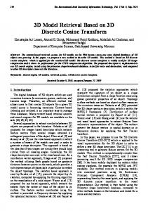
Fig. 1. The six coefficients that are selected to classify.
between subblocks are small which results in low spectral magnitudes in higher frequency components. Hence, a high compression ratio is attainable. However, if the differences between consecutive subblocks are huge, the performance of the 3-D DCT compression will deteriorate. The proposed method solves this problem well.
I. INTRODUCTION
II. ADAPTIVE 3-D DCT CODER
Medical images are widely used in disease diagnosis. These imaging modalities include computerized tomography (CT), magnetic resonance imaging (MRI), ultrasonography (US), and X-rays. These modalities provide flexible means for viewing anatomical cross sections and physiological states and may reduce patient radiation doses and examination trauma. However, medical images have large storage requirements. Due to the limit of network bandwidth and storage capacity, the images must be compressed before being transmitted and stored. Therefore, image compression techniques are needed to reduce the space and time for storage and transmission. In medical applications, where inherently large volumes of digitized images are presented, image compression is indispensable. Detailed descriptions of data compression and medical image compression topics can be found in [1]–[5]. A conventional transform coding scheme involves subdividing an N 2 N image into smaller n 2 n subblocks and performing a unitary transform on each subblock. The goal of the transform is to decorrelate the original signal, and this decorrelation generally results in the signal energy being redistributed among only a small set of transform coefficients. In this way, many coefficients can be discarded after quantization and prior to encoding. Conventional transform coding techniques compress images in a block-by-block manner. Therefore, blocking artifact will appear at high compression ratio. Previous research results on three-dimensional (3-D) compression have been focused on video signals [6] or consecutive CT images [7]–[9]. The proposed method, however, for the first time employs the 3-D compression concept to a 2-D still image. The 3-D discrete cosine transform (DCT) coding method is very efficient when the varieties
Manuscript received October 26, 1999; revised January 19, 2000. This work was supported in part by the National Science Council of the Republic of China under Contract NSC 89-2213-E-006-082. S.-C. Tai and C.-W. Lin are with the Institute of Electrical Engineering, National Cheng Kung University, Tainan, Taiwan. Y.-G. Wu is with the Department of Computer Science and Information Engineering, Leader University, Tainan, Taiwan. Publisher Item Identifier S 1089-7771(00)03948-0.
The description and application of DCT can be found in [10]–[14]. The main idea of the proposed method is compressing the subblocks that have the same characteristic by 3-D DCT. The complete procedure includes classification, segmentation, cuboid formation, 3-D DCT, quantization, and symbol generation. The following subsections describe each procedure in detail. A. Classification In the proposed coder, image subblocks are classified into four classes (from smooth to complex). Collecting those subblocks together with the same activity measure can decrease subblock varieties, and this will raise the compression efficiency. The steps of classification are described as follows:
Input: Original image Output: Class map Step 1. Subdivide the image into 8 8 nonoverlapping subblocks. Step 2. Perform the 2-D DCT on every subblock. Select the six coefficients in every 8 8 matrix as shown in Fig. 1. as folCalculate the activity value lows: "
= v12 + v22 + s12 + s22 + h12 + h22 :
(1)
Step 3. For each subblock , then assign it as class I. IF & , then assign it as ELSE IF class II. & , then assign it as ELSE IF class III. ELSE assign it as class IV. The threshold set fT 1; T 2; T 3g is obtained from repetitive empirical tests. It can be adjusted dynamically to get the best result. However,
1089–7771/00$10.00 © 2000 IEEE
260
IEEE TRANSACTIONS ON INFORMATION TECHNOLOGY IN BIOMEDICINE, VOL. 4, NO. 3, SEPTEMBER 2000
which has already been transmitted. The complete algorithm of segmentation is given as follows. Here, the relative positions of the subblock relationship are shown in Fig. 3.
Input: Class-map of the image. Each entry denotes the class of an 8 8 subblock. Output: Segmentation result. Step 1. Scan the class-map in row-major order. Let the starting position be class-map [0][0] Step 2. For each class in position ( ) & ) ( ][ ] class-map [ ][ ]) If (class-map [ then Segment subblock [ ][ ] and subblock ][ ] to the same segment. [ Mark subblock [ ][ ] as being segmented ] class-map[ ][ ]) If (class-map [ ][ then Segment subblock [ ][ ] and subblock ] to the same segment. [ ][ Mark subblock [ ][ ] as being segmented. Step 3. Repeat Step 2 until all subblocks are segmented. Fig. 2. Classification results of a sonogram. (a) Class I [2960]. (b) Class II [458]. (c) Class III [235]. (d) Class IV [443]. [ 1 ] denotes the number of 828 blocks in that class.
A simple example of the segmentation is given in Fig. 4. In this example, there are two “class 1 ” segments. After segmentation, there are many adjacent subblocks that are of the same class. We collect those subblocks in row-major order to form a 3-D cuboid. C. 3-D Compression The formula to implement 3-D DCT is given as follows:
F (u; v; w) =
n 2 n 2 length of cuboid
01
n
Fig. 3.
1
Relative positions of the subblock.
length of cuboid
8C (u)C (v )C (w )
k=0 1
f (i; j; k) cos
cos
(2j + 1)v� 22n
i=0
01
n
j =0
(2i + 1)u� 2 2 length cos
of cuboid
(2k + 1)w� 22n
(2)
and the 3-D IDCT(inverse DCT) is defined as
f (i; j; k)
length of cuboid
01 n01
n
= u=0
Fig. 4. Collection and segmentation results of the class-map. 1
to simplify the procedure, it is fixed in our simulation. The class information of every subblock is stored in a class-map. This class-map must be transmitted or stored completely to ensure the accurate reconstruction. The class-map is coded in row-major order. Consider the overhead for the class-map in the case of the 828 block based processing, it costs 2=64 = 0:031 25 bit/pixel which is a small overhead to the overall bit rate. Four experimental results of our classification algorithm are given in Fig. 2. The number of each class is listed as well. B. Segmentation After classification, those subblocks with the same class are grouped together to form the 3-D cuboid according to the class-map. At the decoder side, the cuboid structure can be reconstructed by the class-map
1
cos cos
v =0 w =0
C (u)C (v)C (w)F (u; v; w)
(2i + 1)u�
2 2 length
of cuboid
(2k + 1)w�
cos
(2j + 1)v� 22n
22n
(3)
where p
C (w) = 1= 2; for w = 0 for w = otherwise. C (w) = 1; High compression ratios are attainable if the cuboid is long. For most medical images, a dark background occupies the majority region. Therefore, a very long cuboid is possible. This makes the proposed method suitable for medical images. Note that 3-D cuboid coding not only raises the compression ratio, but also alleviates blocky effects in
IEEE TRANSACTIONS ON INFORMATION TECHNOLOGY IN BIOMEDICINE, VOL. 4, NO. 3, SEPTEMBER 2000
Fig. 5.
Illustrator for cuboid length and processing time.
that it processes on total subblocks in the 3-D cuboid together by DCT, not in a block-by-block manner. All 3-D DCT coefficients are uniformly quantized to produce the quantized coefficients. Quantization is performed according to the following equation: Fq (u; v; w )
where
261
=
F (u; v; w ) Q(u; v; w )
(4)
F (u; v; w )
are the coefficients before quantization, Fq (u; v; w ) denotes the quantized quantity, and Q(u; v; w) are values from the quantization table. It is well known that the dc coefficient should be quantized accurately because of its contribution to the average pixel value of that cuboid. Thus, a refined quantizer is used to quantize the dc coefficients. As for ac coefficients, a coarse quantizer is adopted to increase the compression ratio. Note that employing coarse quantization to ac coefficientss does not make the image quality poorer on pure regions since, after quantization, most of the energy is contained in very few low-frequency coefficients, and the majority of the high-frequency coefficients have zero or near-zero values. After that, the quantized coefficients are scanned in a 2-D zigzag pattern and Huffman encoded. Details of this method are given as follows.
classification and segmentation is h > 25, then it will be manipulated as h
25
DCT(8 2 8 2 25) + DCT(8 2 8 2 (h mod 25)):
(5)
The above equation can effectively decrease both the time complexity and space requirements of 3-D DCT. The UCLA PACS system employs full-frame DCT to compress medical images. Therefore, a full-frame DCT and IDCT is also coded for comparison. Under the same circumstances of no fast algorithm, it takes 75 415 s to implement a 5122512 DCT. The time to implement a single DCT (828225) is 0.7428 s. If all the 828 subblocks are arranged into a cuboid, it will form a cuboid 82824096 in size. It takes 29 464 s to compress this cuboid. Applying (5) to this cuboid, it takes 163 2 DCT(8 2 8 2 25) and one DCT(828221) and the run time needed is shorter than 16430:7428 = 121:8192 s. Compared to the time needed for full-frame DCT, it is a significant improvement. However, if fast 2-D DCT is employed, it takes only 33 s to fulfill the 5122512 DCT. Table I lists the run time needed for each algorithm. In the real world, the cuboid length is shorter than 25 for most cuboids, thus it takes less run time. Table II provides the run times needed for three test images. Notice that no fast 3-D algorithm is adopted. However, its run time is comparable to the 5122512 fast 2-D DCT.
Input: Quantized 3-D cuboid whose size is III. SIMULATION RESULTS
Output: Binary bit-stream Pick-out slice[0][0][0]; /* dc term */ for
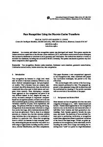
To demonstrate the effectiveness of the proposed technique, the medical images that are used in [14], including sonograms, X-rays, and angiograms, are tested. Decoded images are requested to be without noticeable blocking effects due to the employment of segmentation symbols zig-zag (slice[][][ ]); /* 2-D and the 3-D technique. By the proposed segmentation technique, subzigzag scanning for every individual blocks from the dark background are collected together to form a large slice */ 3-D cuboid which leads to low bit rate. In the center of the angiogram, bitstreams Huffman\_table\_retrieve(symbols);part of the blood vessel and the other part will be gathered together as different 3-D cuboids. The reconstructed image is shown in Fig. 6(b) which achieves a low bit rate (0.109 bit/pixel) with a very high quality (PSNR = 41:56 dB). Differences between the original and decoded D. Computational Complexity Consideration images are illustrated in Fig. 6(c). No apparent difference values could Consider the computational complexity. Fig. 5 illustrates the curve be found. Fig. 6(d) is generated by JPEG. It is obvious that all the docfor cuboid length and the processing time to execute 3D-DCT and tors cannot accept its poor quality. Meanwhile, its compression ratio 3D-IDCT, referring to (2) and (3). No fast 3-D DCT algorithm is and PSNR value are worse than those yielded by the proposed method. adopted. It is obvious that, the longer the cuboid, the more compu- Fig. 7(a) is an original X-ray image. Its bit rate is 0.184 bit/pixel after tational time required. To avoid the high computation complexity compression whose PSNR value is 35.95 dB. The decoded image is drawback that will occur during 3-D DCT calculation, the cuboid shown in Fig. 7(b). Fig. 7(c) illustrates the difference image. A comlength is restricted to a maximum of 25. If the cuboid length after pressed JPEG image is given in Fig. 7(d) whose compression ratio is
262
IEEE TRANSACTIONS ON INFORMATION TECHNOLOGY IN BIOMEDICINE, VOL. 4, NO. 3, SEPTEMBER 2000
TABLE I PROCESSING TIME OF EACH EMPLOYED ALGORITHM
TABLE II THE TIME TO COMPRESS TEST IMAGES
Fig. 7. Test images for an X-ray. (a) Original X-ray image. (b) Decoded X-ray image (bit rate = 0.184, PSNR = 35.95 dB). (c) Difference image. (d) Decoded image by JPEG (bit rate = 0.227, PSNR = 34.12 dB).
Fig. 6. Test images for an angiogram. (a) Original angiogram. (b) Decoded angiogram image (bit rate = 0.109, PSNR = 41.56 dB). (c) Difference image. (d) Decoded image by JPEG (bit rate = 0.148, PSNR = 30.52 dB).
lower than that by the proposed method; however, its PSNR is worse than that of Fig. 7(b). The third test image is shown in Fig. 8(a), which is a sonogram image. It contains texture and artificial lines to record the data about the patient and machine. Subblocks of these regions will be segmented into several different small 3-D cuboids as illustrated in Fig. 8(a). Thus, the bit rate of the decoded image is higher than that of the former two images. However, the quality of the decoded image is still sufficient for the doctor to diagnose the disease. The bit rate is 0.271 bit/pixel with PSNR= 31.46 dB. The decoded image is shown in Fig. 8(c). Fig. 8(d) is the difference image. The JPEG compressed
image, whose compression ratio and PSNR value are lower than those by the proposed strategy, is given in Fig. 8(e). All the experimental results are listed in Table III. In addition, the simulation results for these three test images from [14] are also appended to Table III. As can be seen from Table III, the proposed strategy achieves the lowest bit rates under similar or even higher PSNR values for all test images. Table II lists the run times needed to compress the three test images respectively. Of course, 8 2 8-based JPEG compression is faster than our method, but its performance is worse both in terms of the compression ratio and the decoded image. Two doctors with the Department of Radiology from NCKU hospital and Chang Gung Memorial Hospital are invited to verify the image quality. The proposed algorithm is used to compress 21 different kinds of medical images. After that, the 21 compressed images are studied by the doctors. The diagnoses of all 21 images are correct when the compression ratios are below 30. IV. CONCLUSION AND DISCUSSION The challenges posed by medical imaging are the development of compression algorithms that are nearly lossless for diagnostic purposes
IEEE TRANSACTIONS ON INFORMATION TECHNOLOGY IN BIOMEDICINE, VOL. 4, NO. 3, SEPTEMBER 2000
263
Fig. 8. Test images for a sonogram. (a) Original sonogram. (b) Partial segmentation results of the upper right-hand side. (c) Decoded sonogram image (bit rate = 0.271, PSNR = 31.46 dB). (d) Difference image. (e) Decoded image by JPEG (bit rate = 0.276, PSNR = 29.14 dB). TABLE III SIMULATION RESULTS (CR DENOTES COMPRESSION RATIO)
yet attain high compression ratios. In this communication, an adaptive 3-D DCT image coder is presented. It achieves low bit rates (�0.3 bit/pixel) even with very high fidelity. As a matter of fact, this strategy not only raises the compression ratio but also alleviates blocky effects. The 3-D DCT coding is employed to the 3-D cuboid, therefore the decrement of blocking effects could be attainable. It is very suitable to use the 3-D DCT coder to compress medical images due to the dark background occupies most of the image content. In the segmentation step of the proposed method, it is quite natural to ask: Instead of a 2-D zigzag scan, why not use a 3-D zigzag scan? In fact, we have tried to use a 3-D zigzag scanning pattern to generate the Huffman codes. However, its performance is worse. Currently, there are special purpose architectures for full-frame DCT. Our next goal is to design a fast algorithm and hardware for the 3-D DCT to further decrease its processing time. ACKNOWLEDGMENT The authors would like to thank the reviewers for their comments.
REFERENCES [1] R. C. Gonzalez and R. E. Woods, Digital Image Processing. Reading, MA: Addison-Wesley, 1992. [2] S. Wong, L. Zaremba, D. Gooden, and H. K. Huang, “Radiologic image compression—A review,” Proc. IEEE, vol. 83, no. 2, pp. 194–219, 1995. [3] M. Nelson and J. L. Gailly, The Data Compression Book, 2nd ed. New York: M & T Books, 1996. [4] A. K. Jain, “Image data compression: A review,” Proc. IEEE, vol. 69, pp. 349–389, 1981. [5] T. Kao, S. H. Shieh, and L. C. Wu, “Dynamic radionuclide image compression based on principal components analysis,” in Proc. 1995 IEEE Eng. Med. Biol., pp. 1227–1228. [6] Y. L. Chan and W. C. S, “Variable temporal-length 3-D discrete cosine transform coding,” IEEE Trans. Image Processing, vol. 6, no. 5, pp. 758–763, May 1997. [7] A. Ramaswamy and W. B. Mikhael, “A mixed transform approach for efficient compression of medical images,” IEEE Trans. Med. Imag., vol. 12, no. 4, pp. 803–811, 1996. [8] H. Lee, Y. Kim, A. H. Rowberg, and E. A. Riskin, “Statistical distributions of DCT coefficients and their applications to an interframe compression algorithm for 3-D medical images,” IEEE Trans. Med. Imag., vol. 12, pp. 478–485, Sep. 1993. [9] D. Ho, D. Feng, and K. Chen, “Dynamic image data compression in spatial and temporal domains: Theory and algorithm,” IEEE Trans. Inform. Technol. Biomed., vol. 1, pp. 219–228, Dec. 1997. [10] W. H. Chen and C. H. Smith, “Adaptive coding of monochrome and color images,” IEEE Trans. Commun., vol. COM-25, pp. 1285–1292, 1977. [11] B. Chitprasert and K. R. Rao, “Discrete cosine transform filtering,” Signal Process., vol. 19, pp. 233–245, 1990. [12] K. R. Rao, “Theory and the applications of the discrete cosine transform,” in Jordan Int. Elec. Electron. Eng. Conf., Amman, Jordan, Apr.–May 1985, pp. 259–264. [13] K. R. Rao and J. J. Hwang, Techniques and Standards for Image, Video, and Audio Coding. Englewood Cliffs, NJ: Prentice-Hall, 1996. [14] Y. G. Wu and S. C. Tai, “Medical image compression using 2 2 discrete cosine transform,” Opt. Eng., vol. 37, no. 5, pp. 1539–1546, May 1998.
2