is a registered trademark of Apple Computer, Inc. Applet is a trademark ... Company. IBM is a registered trademark of International Business Machines Corp. ... Component Object Model - a model developed by Microsoft which enables ...... [20] V. Hadzilacos, S. Toueg, âFault-Tolerant Broadcasts and Related Problemsâ, Dis-.
An Agent Architecture for Mobile Network Services: Design and Implementation by
André Peter Schoorl B.Eng., University of Victoria, 1997
A Thesis Submitted in Partial Fulfillment of the Requirements for the Degree of MASTER OF APPLIED SCIENCE in the Department of Electrical and Computer Engineering We accept this thesis as conforming to the required standard
Dr. N. J. Dimopoulos, Supervisor (Department of Electrical and Computer Engineering)
Dr. K. F. Li, Departmental Member (Department of Electrical and Computer Engineering)
Dr. G. C. Shoja, Outside Member (Department of Computer Science)
Dr. R. N. Horspool, External Examiner (Department of Computer Science)
© André Peter Schoorl, 1999 University of Victoria All rights reserved. This thesis may not be reproduced in whole or in part, by photocopying or other means, without the permission of the author.
ii Supervisor: Dr. Nikitas J. Dimopoulos
Abstract As wireless and ubiquitous computing become increasingly affordable and widespread, traditional client-server models for distributing data fail to offer the flexibility needed in mobile computing environments. Although systems have been proposed to address these concerns, most rely on changes to existing infrastructures. This work describes a server hierarchy that uses currently available resources which alleviates some of the common problems associated with data mining from mobile hosts. Although designed for retrieving stored status monitoring information and topology of cable television amplifier networks, the proposed system is general enough to be used for disseminating arbitrary data across a computer network. Client mobility and fault tolerance, if required, are handled through the use of object serialization and intermediate agents.
Examiners:
Dr. N. J. Dimopoulos, Supervisor (Department of Electrical and Computer Engineering)
Dr. K. F. Li, Departmental Member (Department of Electrical and Computer Engineering)
Dr. G. C. Shoja, Outside Member (Department of Computer Science)
Dr. R. N. Horspool, External Examiner (Department of Computer Science)
iii
Table of Contents Abstract ............................................................................................................................... ii Table of Contents............................................................................................................... iii List of Figures .................................................................................................................... vi List of Tables .......................................................................................................................x Trademarks ........................................................................................................................ xi Glossary ........................................................................................................................... xiii Acknowledgements......................................................................................................... xvii
Chapter 1 1.1
1.2
1.3
Distributed Computing Paradigms .......................................................................1 1.1.1 Client-Server Computing .........................................................................2 1.1.2 Remote Procedure Calls ..........................................................................4 1.1.2.1 Programmer Interface ............................................................... 4 1.1.2.2 Fault Tolerance ......................................................................... 6 1.1.2.3 Deadlock ................................................................................... 8 1.1.3 Software Agents ....................................................................................11 1.1.3.1 Stationary Agents.................................................................... 11 1.1.3.2 Mobile Agents......................................................................... 12 1.1.3.3 Implementation Options.......................................................... 13 1.1.4 Applications ...........................................................................................15 Cable Amplifier Networks..................................................................................15 1.2.1 Structure .................................................................................................15 1.2.2 Signals ...................................................................................................17 1.2.3 Topology ................................................................................................19 1.2.4 Nature of Processing ..............................................................................19 1.2.5 Storage and Dissemination Requirements .............................................20 Summary.............................................................................................................22
Chapter 2 2.1 2.2
2.3
Introduction ................................................................................1
Distributed Network Data System............................................24
Server Hierarchy.................................................................................................25 Server Types .......................................................................................................27 2.2.1 Directory Master ....................................................................................27 2.2.2 Directory Server ....................................................................................28 2.2.3 Network Server ......................................................................................28 2.2.4 Data Servers ...........................................................................................29 2.2.4.1 Client Interface........................................................................ 29 2.2.4.2 Data Segmentation .................................................................. 29 2.2.4.3 Recovery Support.................................................................... 30 2.2.4.4 Client Call Order..................................................................... 31 2.2.4.5 Internal States.......................................................................... 33 Client-Server Interaction ....................................................................................34
iv
2.4
2.3.1 Directory Server - Directory Master ......................................................34 2.3.2 Directory Server - Network Server ........................................................34 2.3.3 Network Server - Data Server ...............................................................35 2.3.4 Client .....................................................................................................36 Implementation Considerations..........................................................................37 2.4.1 Connection Handles ...............................................................................37 2.4.2 Query Format .........................................................................................38 2.4.3 Deadlock Avoidance ..............................................................................42
Chapter 3 3.1
3.2
Mobile Data Transfer..........................................................................................45 3.1.1 Traditional Solutions .............................................................................47 3.1.1.1 Client Mobility........................................................................ 47 3.1.1.2 Fault Tolerance and Concurrency........................................... 47 3.1.2 Alternatives ............................................................................................49 Intermediate Agents............................................................................................49 3.2.1 Role in Network .....................................................................................49 3.2.2 Multi-Agent Cooperation ......................................................................51 3.2.3 Client Interaction ...................................................................................55 3.2.4 Benefits ..................................................................................................57 3.2.5 Dispatching and Relocation Issues ........................................................58 3.2.6 Security ..................................................................................................61 3.2.6.1 High-Level Considerations ..................................................... 61 3.2.6.2 Low-Level Considerations...................................................... 62
Chapter 4 4.1
4.2
Agent-Assisted Mobile Data Transfer......................................45
Results and Discussion .............................................................63
Prototype Implementation ..................................................................................63 4.1.1 Modified Server Hierarchy ....................................................................63 4.1.2 Interfaces ...............................................................................................66 4.1.2.1 Network Server ....................................................................... 66 4.1.2.2 Data Server.............................................................................. 68 4.1.3 Implementation Issues ...........................................................................70 4.1.3.1 Security ................................................................................... 70 4.1.3.2 Multi-Threading...................................................................... 71 4.1.3.3 Debugging............................................................................... 71 4.1.3.4 RPC Program Numbers........................................................... 72 4.1.4 Performance Characteristics ..................................................................73 4.1.4.1 Varying the File Size .............................................................. 73 4.1.4.2 Varying the Block Size ........................................................... 78 Test Application - Status Monitoring Data.........................................................81 4.2.1 Comparison of Direct and Agent-Assisted Transfers ............................82 4.2.2 Visualization ..........................................................................................84 4.2.3 Parameters .............................................................................................85
v 4.2.4 4.2.5 4.2.6
Chapter 5 5.1 5.2
Mapping to DNDS .................................................................................85 Caching ..................................................................................................87 Results ...................................................................................................87
Conclusions and Recommendations.........................................89
Conclusions ........................................................................................................89 Recommendations and Future Work ..................................................................91
Bibliography..................................................................................................94 Appendix A Sample Cable Amplifier Network Topology.........................99 Appendix B Network Server Interface Definition ...................................100 Appendix C Data Server Interface Definition..........................................105 Appendix D Debug Library Header File ..................................................107
vi
List of Figures Figure 1.1:
Client-server model - one or more client programs communicate over a network with a server which provides some resource. .............................3
Figure 1.2:
Remote procedure call communication [4]...............................................5
Figure 1.3:
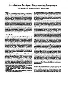
Structure of cable amplifier networks. Signals propagate along the forward path from the head-end through high-bandwidth trunk amplifiers, then through smaller networks of distribution amplifiers, before arriving at destination subscribers. There is also a lower bandwidth reverse path which flows in the opposite direction. ....................................................16
Figure 1.4:
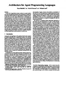
Forward pilot signal over a one week interval for amplifier SMT_2208 from the Oshawa cable amplifier network..............................................18
Figure 1.5:
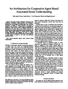
Temperature signal over a one week interval for amplifier SMT_2208 from the Oshawa cable amplifier network..............................................18
Figure 1.6:
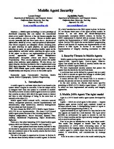
Data flow of cable amplifier network status monitoring signals and topology information. Data collectors receive status monitoring signals from the reverse path of a cable amplifier network; the resulting databases are sent to one or more storage locations using the file transfer protocol (FTP) at regular intervals...................................................................................21
Figure 2.1:
Server hierarchy. .....................................................................................25
Figure 2.2:
Example of client control flow during a multiple session connection including an off-line period and subsequent reconnection. ....................32
Figure 2.3:
Data server state transitions during information transaction with client. For simplicity, the majority of self-loops are not shown. .......................33
Figure 2.4:
Querying by network server amongst data servers to determine location of unknown data, or to determine how data is spread across servers..........35
Figure 2.5:
Structure of Universal Unique Identifier (UUID). Values in square brackets indicate the number of bits allocated for each field..................38
Figure 2.6:
Example of the tree structure used to represent a generic format for DNDS queries. From the root of the tree, several high-level data groups are defined - in this case, cable amplifier network data and file transfer requests. Further information is similarly specified in sub-trees, with the lowest level details occupying the leaf nodes of the tree. The highlighted path represents a sample of the stream necessary to specify a particular file.39
Figure 2.7:
Proposed encapsulation of query within a byte stream. A number of UUIDs are included which define the path taken in the DNDS tree. In addition, an optional payload field can be specified for further parameters for example, the start time and end time defining an interval of data to be obtained...................................................................................................40
vii Figure 2.8:
Modified portion of tree structure after dynamic insertion of new site, SiteC........................................................................................................42
Figure 2.9:
Example of deadlock condition between two synchronous RPC servers. Solid circles represent servers blocked executing a service routine, while dotted circles represent servers awaiting a connection. A server might invoke an RPC to another server for a variety of reasons - for example, propagation of network information. ......................................................43
Figure 2.10:
Deadlock between two synchronous servers A and B (a), and its avoidance through consistent use of forked processes to make high-level requests (b). Any necessary state changes by the child can be sent back to the parent server in a subsequent call (c). Although the temporary process B* inherits a copy of its parent’s state, it cannot receive RPC requests of its own..........................................................................................................44
Figure 3.1:
Client mobility between requests (off-line mobility)..............................46
Figure 3.2:
Illustration of data transfer with and without intermediate agent. ..........50
Figure 3.3:
Initial client communication with a mobile agent in Victoria (a), mobility by client and corresponding rendezvous by agent (b), and subsequent re-connection in Toronto (c). ..................................................................51
Figure 3.4:
Multiple agents combined to provide additional features. Parallel redundancy offers additional fault tolerance, while serial chaining provides pipelining and some control over the routing of packets........................52
Figure 3.5:
Cache synchronization between parallel agents. A primary agent is elected to act as a representative for a group of agents, which it must keep up to date in case of failure. Recovery is implemented in a standby-sparing fashion by coordinating with the parent network server.........................54
Figure 3.6:
Sample illustration of client interaction with agent, data server, and network server. Once a session is opened, retrieval and caching by the agent occurs asynchronously. This simplified diagram does not show threading or forking. ...............................................................................................56
Figure 3.7:
Example of acceptor site determination during dispatching of intermediate agent. A combination of factors shown next to each acceptor site may be used by the network server to determine the best candidate. In this case, Site 4 will likely be chosen since it has low load average, high throughput, and reasonable available disk space........................................................59
Figure 3.8:
Trace of remote procedure calls used to migrate a mobile agent from one host to another. The system starts with a mobile agent executing on some host (a). The parent network server dispatches a second agent on the target host (b), and informs the original agent to migrate (c). This causes a transfer of state information between agents (d), after which the original agent exits, leaving only the mobile agent on the target host (e). If any of the
viii steps fail, the mobile agent is left on the original host as in (a)..............60 Figure 4.1:
Modified server hierarchy.......................................................................63
Figure 4.2:
Class hierarchy of network objects. Abstract classes are shown in rectangular boxes, while instantiable classes are shown in rounded boxes. ......................................................................................................64
Figure 4.3:
Threads used in agent data transfer.........................................................71
Figure 4.4:
Comparison of file transfer timings between two machines on a LAN using the distributed network data system (DNDS) prototype and common system commands. The block size for the DNDS server was 256 KB. Each data point is calculated as the average of three independent trials, with error bars showing the standard deviation. .............................................75
Figure 4.5:
Consecutive execution of programs (a), in comparison with program interleaving (b) used in DNDS performance testing. This technique helps to reduce the effects of indeterminate network behaviour for making performance comparisons. ......................................................................76
Figure 4.6:
Comparison of file transfer timings from a machine in Toronto, Ontario to a machine in Victoria, British Columbia using the distributed network data system (DNDS) prototype and common system commands. Intermediate agents were dispatched to a host in Richmond, British Columbia. The block size for the DNDS server was 256 KB. Each data point is calculated as the average of ten interleaved trials, with error bars showing the standard deviation. ............................................................................77
Figure 4.7:
Comparison of time to transfer 1 MB file between two machines on a LAN using the distributed network data system (DNDS) prototype and varying block sizes. Each data point is calculated as the average of ten interleaved trials, with error bars showing the standard deviation. ........79
Figure 4.8:
Comparison of time to transfer 1 MB file from a machine in Toronto, Ontario to a machine in Victoria, British Columbia using the distributed network data system (DNDS) prototype and varying block sizes. Intermediate agents were dispatched to a host in Richmond, British Columbia. Each data point is calculated as the average of ten interleaved trials, with error bars showing the standard deviation. ...........................80
Figure 4.9:
Close-up of the transfer times shown in Figure 4.8 using block sizes greater than or equal to 1 KB..................................................................81
Figure 4.10:
Visualization of status server data using Java applet..............................84
Figure 4.11:
Communications overview of the interface between the status monitoring visualization applet and the distributed network data system.................86
x
List of Tables Table 4.1:
Data server portion of network server interface. ...................................... 66
Table 4.2:
Client portion of network server interface. ............................................... 67
Table 4.3:
Client options available in network server request. Multiple options may be specified by performing a bit-wise OR of the desired enumerations. ....... 68
Table 4.4:
Client information transaction portion of data server interface. ............... 69
Table 4.5:
ONC RPC program numbers .................................................................... 72
Table 4.6:
Summary of file transfer timings in Figure 4.4 using least-squares linear interpolation. ............................................................................................. 74
Table 4.7:
Summary of file transfer timings in Figure 4.6 using least-squares linear interpolation. ............................................................................................. 78
Table 4.8:
Comparison of transfer times for remote retrieval of status monitoring data for amplifier SMT_100 from the Rogers cable amplifier network in Mississauga, Ontario. The first run consists of three and a half weeks of data while the second run consists of seven weeks of archived data, both starting from May 6, 1999. DNDS servers were executed on a machine in Toronto, Ontario while the client was in Victoria, British Columbia. ............................................ 83
Table A.1: Portion of the topology from the cable amplifier network in Newmarket, Ontario on April 14, 1997. ........................................................................ 99
xi
Trademarks Many of the designations used by manufacturers and sellers to distinguish their products are claimed as trademarks. Trademarks and registered trademarks used in this work, where the author was aware of them, are listed below. All other trademarks are the property of their respective owners. ANSI
is a trademark of the American National Standards Institute.
Apple
is a registered trademark of Apple Computer, Inc.
Applet
is a trademark of Wilson Window Ware.
C++
is a trademark of American Telephone and Telegraph Company, Inc.
C-COR
is a registered trademark of C-COR Electronics Inc.
Concordia is a trademark of Mitsubishi Electric America, Inc. CORBA
is a registered trademark of Object Management Group, Inc.
Ethernet
is a registered trademark of Xerox, Inc.
HP-UX
is a registered trademark of Hewlett-Packard Company.
IBM
is a registered trademark of International Business Machines Corp.
IEEE
is a registered trademark of the Institute of Electrical and Electronics Engineers, Inc.
Intel
is a registered trademark of Intel Corp.
Java
and all Java-based trademarks and logos are trademarks or registered trademarks of Sun Microsystems, Inc. in the United States and other countries.
Linux
is a registered trademark of Linus Torvalds.
Lycos
is a registered trademark of Carnegie Mellon University.
MacOS
is a registered trademark of Apple Computer, Inc.
Microsoft is a registered trademark of Microsoft Corp.
xii Netscape Netscape Certificater Server, Netscape FastTrack Server, Netscape Navigator, Netscape ONE, SuiteSpot, and the Netscape N and Ship’s Wheel logos are registered trademarks of Netscape Communications Corporation in the United States and other countries. Netscape Communicator is also a trademark of Netscape Communications Corporation, which may be registered in other countries. NFS
is a registered trademark of Sun Microsystems, Inc.
Odyssey
is a trademark of General Magic, Inc.
Pentium
is a registered trademark of Intel Corp.
POSIX
is a trademark of the Institute of Electrical and Electronics Engineers, Inc.
Rogers
is a trademark of Rogers Communications, Inc.
Solaris
is a registered trademark of Sun Microsystems, Inc.
Sony
is a registered trademark of Sony Corp.
Sun
is a trademark of Sun Microsystems, Inc.
SPARC
and UltraSPARC are registered trademarks of SPARC International, Inc. Products bearing SPARC trademarks are based upon an architecture developed by Sun Microsystems, Inc.
Telescript is a trademark of General Magic, Inc. UNIX
is a registered trademark of The Open Group.
Voyager
is a trademark of ObjectSpace, Inc.
xiii
Glossary Aglet
Agile Applet - a Java-based autonomous software agent.
ANSI
American National Standards Institute - the primary organization for fostering the development of technology standards in the United States.
API
Application Program Interface - a set of routines, protocols, and tools for software application programming.
ASDK
Aglets Software Development Kit - an SDK provided by IBM to develop Aglets.
CGI
Common Gateway Interface - a specification for transferring information between a World Wide Web server and a CGI program, which may be written in any programming language.
COM
Component Object Model - a model developed by Microsoft which enables programmers to develop objects which can be accessed by any COM-compliant application.
CORBA
Common Object Request Broker Architecture - a model developed by an industry consortium known as the Object Management Group which allows objects written in different languages or running on different operating systems to communicate with each other.
DCE
Distributed Computing Environment - a suite of technology services developed by The Open Group for creating distributed applications that run on different platforms.
DES
Data Encryption Standard - a 56-bit symmetric-key encryption method developed in 1975 and standardized by ANSI in 1981 as ANSI X.3.92.
DNDS
Distributed Network Data System - a system designed for storing large amounts of data amongst hosts on a computer network, and disseminating this information to clients in a manner that supports authentication, control, security, mobility, and fault tolerance.
DoS
Denial of Service - a form of attack aimed at crippling a device or network so as to make it unusable by legitimate users, often by using a large number of normally legitimate operations in a technique known as “flooding”.
FSF
Free Software Foundation - an organization founded in 1984 by Richard Stallman dedicated to the generation and distribution of free software. The most well known effort of the FSF is the GNU project.
xiv FTP
File Transfer Protocol - the protocol used on the Internet for sending files.
GUI
Graphical User Interface - a program interface that takes advantage of a computer’s graphics capabilities to make the program easier to use.
GNU
GNU’s Not Unix - a Unix compatible software system developed by the Free Software Foundation (FSF).
HTML
Hypertext Markup Language - the authoring language used to create documents on the World Wide Web.
HTTP
Hypertext Transfer Protocol - the protocol for exchanging files (text, graphic images, sound, video, and other multimedia files) between a server and web browsers on the World Wide Web.
IEEE
Institute of Electrical and Electronics Engineers - an organization composed of engineers, scientists, and students best known for developing computing and electronics standards. The IEEE describes itself as “the world’s largest technical professional society - promoting the development and application of electrotechnology and allied sciences for the benefit of humanity, the advancement of the profession, and the well-being of our members.”
I/O
Input / Output - describes any operation, program, or device that transfers data to or from a computer.
IP
Internet Protocol - the inter-network data delivery protocol used on the Internet.
ISO
International Organization for Standardization - an international organization composed of national standards bodies from over 100 countries. ISO is not an abbreviation - it is a word, derived from the Greek isos, meaning “equal”.
JDK
Java Development Kit - an SDK provided by Sun Microsystems for developing programs written in Java.
JVM
Java Virtual Machine - the term used by Sun Microsystems to describe the software that acts as an interface between compiled Java binary code and the microprocessor that actually performs the program’s instructions.
LAN
Local Area Network - a computer network that spans a relatively small area. Typically, a LAN is limited to a single building or a small group of buildings.
xv MAC
Media Access Control - the MAC address is a computer’s unique hardware number.
NFS
Network File System - a method designed by Sun Microsystems of sharing files between machines on a network by making them appear to be available on a local filesystem.
ONC
Open Network Computing - a network architecture developed by Sun Microsystems in the 1980s, including a specification for remote procedure calls (RPC).
OSI
Open System Interconnection - an ISO standard for worldwide communications that defines a networking framework for implementing protocols in seven layers.
POSIX
Portable Operating System Interface - a set of IEEE and ISO standards that define an interface between programs and operating systems. Programs conforming to the POSIX standard have reasonable assurance of successful porting to other POSIX-compliant operating systems.
RMI
Remote Method Invocation - a set of protocols developed by Sun Microsystems which allows Java objects to communicate with other remote Java objects.
RPC
Remote Procedure Call - a high level primitive used to encapsulate clientserver interaction. RPC encapsulates the service provided by the server to make it appear as a function call by the client.
SCADA
System Control And Data Acquisition - a collection of computers, communications equipment, sensors, and other devices that when put together will monitor and control an engineering system.
SDK
Software Development Kit - a set of programs used by a computer programmer to write software applications.
SMT
Status Monitoring Transponder - the SMT module of a cable amplifier is responsible for sampling and quantization of analog sensor signals, as well as providing this information to a central monitoring system.
STL
Standard Template Library - a C++ library of container classes, algorithms, and iterators which provides many of the basic algorithms and data structures of computer science.
xvi TCP
Transmission Control Protocol - a connection-oriented network transport layered on top of IP. TCP enables two hosts to establish a connection and exchange streams of data. TCP guarantees delivery of data and also guarantees that packets will be delivered in the same order in which they were sent.
TCP/IP
Transmission Control Protocol / Internet Protocol - the basic communication language or protocol of the Internet.
TMR
Triple-module redundancy - the basic concept of TMR is to triplicate the components of a system and perform a majority vote to determine the output of the system. If one of the modules becomes faulty, the two remaining fault-free modules mask the results of the faulty module when the majority vote is performed.
UDP
User Datagram Protocol - a connectionless network transport layered on top of IP, which uses datagram sockets. UDP offers a way to send and receive datagrams directly, but does not offer any guarantees on the delivery or order of datagrams received.
UUID
Universal Unique Identifier - an immutable, 128 bit number which is guaranteed to be unique across time and space.
WAN
Wide Area Network - a computer network that spans a relatively large geographical area. Typically, a WAN consists of two or more local-area networks (LANs).
WWW
World Wide Web - a subset of the Internet which runs servers to distribute HTML documents and supporting files.
XDR
External Data Representation - the ONC standard for portable data transmission to ensure consistency between architectures.
xvii
Acknowledgements I wish to thank my supervisor, Dr. Nikitas Dimopoulos, for his guidance and support throughout the research and preparation of this thesis. I would also like to express my gratitude to Dr. Kin Li for his encouragement and advice on entry into graduate studies. As well, I am grateful to Nicolaos Kouronakis for providing assistance as a graduate student, and to Caedmon Somers for in depth discussions on many of the core concepts in this thesis. Finally, I would like to thank my family and friends for their support. It should be acknowledged that this research would not have been possible without the financial support of the Canadian Cable Labs Fund, as well as a University of Victoria Fellowship.
18
For my parents, Theodora Anthonia Cornelia Schoorl and Martinus Johannes Schoorl, for their support through the years.
1
Chapter 1 Introduction
1.1 Distributed Computing Paradigms Several paradigms exist for distributed computing. Some client-server technologies have remained virtually unchanged for decades, while more recent approaches such as COM and CORBA [8] continue to be actively developed. However, even the most sophisticated of these technologies have roots in the fundamental techniques of messaging, simple datagrams, sockets, remote procedure calls, and conversations [18]. In general, these methods can be split into two categories – synchronous and asynchronous protocols. Synchronous data communication requires that each end of an exchange of communication respond in turn without initiating a new communication. Asynchronous communication pertains to processes that proceed independently of each other until one process needs to “interrupt” the other process with a request. An example of a synchronous protocol is the remote procedure call, while message passing is the classical asynchronous method. Following the introduction of these basic client-server technologies, several approaches arose in attempts to improve upon performance and alleviate some of the problems and limitations which were discovered. For example, the use of several remote procedure calls to perform a client-server transaction may use more network bandwidth than sending a more complicated query to a server, performing necessary computation or accessing of databases locally, and returning the results to the client [18]. Initial attempts used the concept of process migration in an attempt to save bandwidth and increase performance. However, movement of an entire address space from one machine to another, as utilized by this technique, makes it difficult to return the results to the client without returning the entire process as well [64].
2 The concept of remote evaluation programming [52] improves on process migration by allowing a program to be sent within a request, having it executed on a remote server, and returning only the results to the client. However, lack of state information limits the usefulness of remote evaluation based systems. Mobile objects were subsequently developed, in which object-oriented programming techniques are used to encapsulate state as well as code. In recent years, the mobile agent [28] concept has arisen from these earlier clientserver technologies. Mobile agents extend on the functionality of mobile objects by adding autonomous and asynchronous execution capabilities. This allows mobile agents to decide for themselves the most efficient means to obtain data, or route around network bottlenecks. Agents may also be able to perceive their environment and communicate with other agents, making previously difficult fault-tolerance and distribution heuristics possible. In this section, a brief introduction of client-server and distributed computing is given. Remote procedure calls are discussed as a representative for well known synchronous client-server transactions, while mobile agents represent current asynchronous technologies. Some of the benefits and drawbacks of these methodologies are highlighted, as well as their relevance to the remainder of this work.
1.1.1 Client-Server Computing Client-server computing describes the relationship between two computer programs in which one program, the client, makes a service request to another program, the server, which fulfills the request. Although the client-server model shown in Figure 1.1 can be used by programs executing at a stand-alone physical location, the underlying concept is more useful when applied in networks. In a network, the client-server model provides a convenient way to interconnect programs that are distributed efficiently across different locations. In this model, one server, sometimes called a daemon, is activated and awaits client requests. Clients and servers can communicate with one another using many differ-
3 ent protocols, the simplest being the sending and receiving of datagrams. Typically, multiple client programs share the services of a common server program. Both client programs and server programs are often part of a larger program or application.
Client ...
Server resource
Client Network Figure 1.1: Client-server model - one or more client programs communicate over a network with a server which provides some resource. Client-server computing can also be thought of as an extension to modular programming. The modular programming concept is based on the assumption that separation of software into smaller components, or modules, eases development and simplifies maintainability. The client-server model is formed upon realization that execution of these modules need not necessarily occur in the same memory space. That is, modules comprising an application may be physically separated over a network. Once separated, the calling module is referred to as the client, while the called module performing the execution is referred to as the server. Using commonly defined interfaces and a platform neutral network format, clients and servers may have heterogeneous operating systems and hardware. Typically, server processes are run on high-performance computers while client architectures may range from low-end portable computers to high-performance workstations in themselves. Clients generally rely on servers for resources such as files, devices, or computational abilities. Examples of client-server computing include servers which provide the current time of day, the weather, or retrieve your e-mail messages. Arbitrarily sophisticated systems are possible, such as database management system servers running on platforms specially designed and configured to perform queries, or file servers running on platforms with special elements for managing files. With respect to the Internet, the best known use
4 of the client-server model is the World Wide Web (WWW). A web browser is a client program that requests services (the sending of web pages or files) from a web server (also known as a HTTP server), typically residing on another computer somewhere on the Internet.
1.1.2 Remote Procedure Calls The remote procedure call (RPC) is a high level primitive that directly supports clientserver communication. RPC encapsulates the service provided by the server to make it appear as a function call by the client. This capability may be implemented using the standard client-server send and receive primitives, but these implementation details are hidden from the programmer. RPC is synchronous in nature to maintain client call order but the underlying implementation may use asynchronous messaging.
1.1.2.1
Programmer Interface
The result of RPC encapsulation is an interface which, from the programmer’s perspective, makes invoking a remote procedure appear similar to the traditional procedure call mechanism of pushing parameters, context, and a return address onto the stack, then executing a jump to the procedure’s starting address. In an imperative programming language, this is typically done through an interface such as return_value function(argument1, argument2, …, argumentN, result1, result2, …, resultM)
In the case of a remote procedure call, the client opens a communications channel to the server to have it perform a procedure on its behalf. Parameters can be passed as before, but are typically encoded into a platform neutral state, such as the external data representation (XDR), before being sent across the network. The programmer interface, however, now appears as a call to a service similar to call service(argument1, argument2, …, argumentN, result1, result2, …, resultM)
5 Certain RPC implementations may not support multiple results and arguments within these services, but in these cases aggregate types can always be used. Both the client and server communicate through stubs which encapsulate the underlying network protocols to make transactions appear as conventional procedure calls, as shown in Figure 1.2. Both the client and the server must use a common interface, although the two parties may not necessarily have matching hardware or software. Client
Server
calling procedure
called procedure results
arguments results
arguments
Client Stub
Server Stub
network transport
network transport
request messages
reply messages
reply messages
request messages
Network Figure 1.2: Remote procedure call communication [4]. While a local procedure can generally be invoked in a few microseconds (not including the execution time of the procedure itself), the RPC introduces overhead due to marshalling, transmission, and unpacking, and typically has a latency of a few milliseconds [18]. This remote object invocation latency is typically 10,000 to 100,000 times larger than that of local objects, and given the relative rates at which processor speed and network latency speeds are changing, the difference in the future promises to be at best no better, and will likely be worse [60]. Even so, the inherent distributed nature of available resources makes use of client-server primitives, such as RPC, unavoidable in modern computing systems.
6 Unlike socket connections, which are assigned to a specific port number, RPC uses a daemon called the portmapper which controls all RPC connections. To distinguish between servers, the portmapper uses program and version numbers. The program number must be unique to each server on a system, while the version number can be used to allow different generations of clients and servers to co-exist [4]. Clients cannot query for these values directly, but must know the program and version numbers of a specific server a priori. Servers typically register themselves in the portmap on creation. For security, most remote procedure call implementations provide some form of authentication and encryption facility. For example, the Open Network Computing (ONC) RPC implementation [51] provides Data Encryption Standard (DES) public key encryption. However, these authentication and encryption techniques add significant overhead [57].
1.1.2.2
Fault Tolerance
With respect to fault tolerance, remote procedure calls raise previously unseen issues. As opposed to local functions, where the caller of a function resides on the same machine as the callee, remote procedure calls involve two processes (i.e., the client and the server) which typically reside on physically independent machines. If a fault occurs on a system invoking a standard procedure call, both the caller and the callee are affected equally. However, in a remote procedure call, the client and server nodes are independent, meaning that either or both machines may have independent failures. Furthermore, the communications network may also fail - either losing messages, or by re-ordering or otherwise corrupting messages - during execution of a remote procedure call. Under failure conditions, the semantics of the RPC cannot be like that of a simple procedure in a sequential program, in which the failure of a node means the failure of the caller as well as the callee, and the failure of the communication network has no effect [22]. This means that remote procedure calls are made in an environment in which failures
7 are common. To enumerate the possible scenarios, the classification scheme for the semantics of remote procedure calls described in [37] and [42] is adopted. This is given by: •
At least once: The remote procedure has been executed one or more times if the invocation terminates normally. If it terminates abnormally, nothing can be said about the number of times the remote procedure has executed. It may have executed partially, zero, one, or multiple times.
•
Exactly once: The remote procedure has been executed exactly once if the invocation terminates normally. If it terminates abnormally, then it can be asserted that the remote procedure has not been executed more than once.
•
At most once: This is the same as exactly-once semantics if the invocation terminates normally. If it terminates abnormally, then it is guaranteed that the remote procedure has been executed completely once, or has not been executed at all.
These failure cases of RPC give rise to many scenarios where the state of the system cannot be guaranteed to be consistent. For example, consider a server whose entire state consists of a single number, which can be incremented using a remote procedure call by a client. Under failure conditions, if a client invokes this RPC, nothing can be said about whether the server’s counter was actually incremented or not. There are mechanisms to avoid these scenarios caused by network or processor failure - for example, the client may retry the remote procedure call. However, this causes another problem - orphans [42], which are the unwanted execution of remote procedures. These can also arise because of timing or synchronization problems. The choice of the transport protocol also plays a role in the fault tolerance of an application. Typical RPC implementations provide mechanisms for use of either UDP or TCP as transport protocols. UDP provides a simple mechanism for transmitting datagrams directly - however, it does not guarantee delivery nor maintains order of these datagrams at the receiver, meaning it is not completely reliable. Using UDP, even with additional user-
8 level code, if a datagram is lost, neither server nor client are aware of it [4]. On the other hand, TCP is reliable and handles these issues internally. However, there is a small amount of overhead involved, particularly when the initial connection is established. Although many of the failure cases of RPC can be handled transparently by the underlying implementation, a server with internal state information may still be affected by certain types of failure. For example, an orphan process could inadvertently modify a server’s state, making it inconsistent with that of the corresponding client. For these reasons, the possibility of partial or total failure must still be accounted for in the implementation of systems which utilize remote procedure calls.
1.1.2.3
Deadlock
Since remote procedure calls are generally implemented as synchronous and blocking calls1, the possibility for deadlock exists. Specifically, this occurs when an individual server cannot handle service requests because it is blocked making a request of its own. If a cycle in these client-server dependencies exists, then the system is said to have deadlocked. To see why this is the case, we have to consider the four necessary conditions for deadlock [53], [17], from operating system theory: 1. Mutual exclusion condition - Resources exist that are not sharable. 2. Non-preemption condition - Once a resource is given to a process, it cannot be revoked until the process voluntarily gives it up. 3. Hold and wait, or partial allocation condition - Processes currently holding resources granted earlier can request new resources. 4. Cycles, or circular wait condition - There must be a circular chain of two or more processes, each of which is waiting for a resource held by the next member of the chain. 1.
Asynchronous RPC with or without replies also exists, such as QRPC used in Rover [25]. Asynchronous RPC is useful in applications where precise synchronization is not required. In certain cases, use of asynchronous messages may offer improved performance over synchronous methods [1]. However, due to lack of standards, documentation, and increased design complexity, its use is much less common than synchronous RPC.
9 Rewording this in terms of synchronous RPC systems, processes represent clients and resources represent access to particular servers. The first condition, mutual exclusion, is satisfied because traditional single threaded servers can only deal with one client at a time, thus making access to a server itself a non-sharable resource. Similarly, the non-preemption condition is satisfied because once a server-side RPC begins executing, it does not terminate until completion. Partial allocation occurs because remote procedures themselves may act as clients, and request more resources - which allows circular dependencies to exist, satisfying the remaining condition. All four conditions must be satisfied in order to create a deadlock. In synchronous RPC, the first three conditions are generally unavoidable, but the fourth condition (cycles) can often be avoided. There are several ways to deal with deadlock in distributed systems. The first method, deadlock recovery, takes no steps at preventing deadlock, but attempts to correct the situation once it has occurred. In this technique, deadlock detection schemes are used which analyze the state of the system to check if the four necessary conditions for deadlock are satisfied - especially, if a cycle exists in the client-server dependencies. Once detected, suitable recovery mechanisms are employed. In the worst case, the system may have to be restarted or rebooted. A less drastic approach is to take back a resource from a process to break a cycle. However, if the resource is not preemptable, this may force termination of the process. Slightly more sophisticated techniques to gracefully undo committed state changes include checkpointing [27] and rollback [12], which are common in database systems. In terms of RPC, deadlock detection is usually implemented using time-outs for client calls. However, even when deadlock is detected in an RPC system, recovery from such situations can still be a problem. Alternatively, we can use deadlock prevention to eliminate the possibility of a deadlock occurring in the first place. Theoretically, we can prevent deadlock by removing any one of the four necessary conditions. The partial allocation condition may be avoided by forcing a process (or client) to allocate all the resources it will ever need at start-up time, or by making it release all of its resources before allocating any more. However, placing
10 either of these restrictions may not be practical, especially when a large number of resources is involved. Therefore, as mentioned previously, in synchronous RPC systems it may only be possible to remove the possibility of cycles. Typically, the circular wait condition is prevented through an algorithm known as hierarchical allocation. In this algorithm, resources are first assigned numbers. Although each resource is generally given a unique number, this is not a strict requirement for the algorithm to work. Using these assignments, if processes (or clients) always request resources (or servers) in increasing numerical order, then deadlock cannot occur [53]. The final approach for handling deadlock is called deadlock avoidance. In this technique, resources are not necessarily granted to a requesting process (or client) even if they are currently available, if by granting the resource places the system in a possible unsafe state. Typically, this safety check is done in a worst case fashion, assuming that all running processes immediately request all the remaining resources available to them. The most well known technique is the “Banker’s Algorithm” by E. W. Dijkstra [9]. However, use of such an algorithm requires delaying client requests for resources until the system is in a safe state, which may be unacceptable when communicating over a network. Furthermore, since deadlock avoidance requires central knowledge and control, its usefulness is limited in distributed systems. Remote-procedure call implementations generally provide an accompanying time-out for client requests, which can be used to detect deadlock. However, use of such time-outs alone makes detection of faults of the network or remote node indistinguishable from that of deadlock conditions. As well, reliance on time-outs may introduce large latencies in client communications. Therefore, deadlock must be avoided since it can cause unreliable service as well as leave the system in a possible inconsistent state. It is left to the programmer of a distributed RPC application to avoid deadlock, either by enforcing an order on resource allocation, or by other means, such as the use of multiple threads or forked processes, to eliminate the possibility of cyclical dependencies.
11
1.1.3 Software Agents The software agent concept takes the idea of client-server computing a step further by combining both client and server functionality into a single entity and allowing it to perform actions independently. Although the theory behind agents has been around for some time, agents have become more prominent with the recent growth of the Internet. Agents seem to offer benefits not possible in conventional programs - but what distinguishes an agent from a program? Several definitions provide insight into this question. Wooldridge and Jennings [66] provide the following definition of an agent - a hardware or (more usually) software-based computer system that enjoys the following properties over conventional programs: •
autonomy - agents operate without the direct intervention of humans or others, and have some kind of control over their actions and internal state;
•
social ability - agents interact with other agents (and possibly humans) via some kind of agent-communication language;
•
reactivity - agents perceive their environment, (which may be the physical world, a user via a graphical user interface, a collection of other agents, the Internet, or perhaps all of these combined), and respond in a timely fashion to changes that occur in it;
•
pro-activeness - agents do not simply act in response to their environment, they are able to exhibit goal-directed behaviour by taking the initiative.
A more succinct definition is that an autonomous agent is a system situated within and a part of an environment that senses that environment and acts on it, over time, in pursuit of its own agenda and so as to affect what it senses in the future [13].
1.1.3.1
Stationary Agents
Mobility is not a necessary requirement for a program to be called an agent - there are many applications that can still benefit from agents which do not move after their initial creation. These agents are termed stationary agents and can still provide many of the
12 aforementioned properties of agents. In particular, features such as asynchronous and autonomous execution may still be useful properties even when execution is limited to a single system. An example is the user, information, query, and support agents described in the ISAME architecture [43]. Java applets could also be considered stationary agents because after they are initially sent to a target virtual machine to execute, they generally do not move to other hosts. If a stationary agent needs information from another system, or wishes to communicate with another agent on a remote system, it cannot migrate to the other system itself, but must use some other means, such as remote procedure calls, in order to communicate with the remote system. Therefore, while stationary agents are still useful in some applications, it is evident that allowing an agent to be mobile greatly increases its flexibility. A mobile agent can either move data to itself, or move itself to the data - whichever method is preferred.
1.1.3.2
Mobile Agents
A mobile agent is a software entity able to travel throughout a network, to negotiate with other entities (agents or otherwise) so as to achieve a specific task and to reach objectives [6]. Mobile agents control where computation happens by moving programs as well as data. While there are no applications that cannot be solved without mobile agents, there are many applications which can benefit from their use. The work in [30] describes seven main benefits to using mobile agents: 1. They reduce the network load - an agent may move to a destination host where it may perform computation locally, rather than having data transmitted across the network. 2. They overcome network latency - in large systems, latency becomes a major problem in maintaining control. An agent may be dispatched to perform some actions locally - for example, in a real-time system. 3. They encapsulate protocols - agents can communicate with servers or other agents using their own proprietary protocols, rather than relying on a host’s native means
13 of communication, which may be constrained by legacy software. 4. They execute asynchronously and autonomously - once an agent is dispatched, it becomes an independent entity. 5. They adapt dynamically - agents can perceive their environment and act on their own to solve a problem. 6. They are naturally heterogeneous - agents are generally dependent only on their execution environment, and not the specific hardware or software they are running on. 7. They are robust and fault-tolerant - mobile agents’ ability to migrate between hosts makes them attractive for implementing fault-tolerant systems. Examples of large-scale industrial efforts in which mobile agents have been utilized include General Magic’s Odyssey [40], ObjectSpace’s Voyager [59], Mitsubishi’s Concordia [65], IBM’s Aglets Software Development Kit (ASDK) [31], and multi-agent data collection in Lycos [15]. Applications for mobile agents include e-commerce, personal assistants to perform tasks on behalf of their creators, distributed information retrieval such as WWW searches, and information dissemination such as electronic news or software updates. Mobile agents are well suited to electronic commerce applications [16], since transactions often require real-time access to remote resources.
1.1.3.3
Implementation Options
Most mobile agent implementations tend to be in Java2 - Concordia, Odyssey, Voyager, and Aglets are all Java based. Multi-platform support, built-in serialization (a mechanism for reading and writing objects to and from I/O streams), dynamic loading of objects, and wide-spread adoption of the Java virtual machine make Java attractive for implementing mobile agent systems.
2.
Some authors [64] quote Java as the “language of choice for mobile agent systems”.
14 However, Java is not without its drawbacks. Since Java is generally interpreted at the byte code level on a general purpose microprocessor (e.g., the Intel Pentium), performance can be a problem in both I/O bound and computationally bound applications, in comparison with natively compiled code. Furthermore, language constraints such as lack of multiple inheritance support may make a particular design difficult to map into Java, although workarounds can be achieved using Java interfaces. The work in [44] describes additional limitations with Java in relation to mobility and persistence support: 1. lack of persistence support makes Java access to databases non-standard. 2. it is difficult to transfer complex data structures between Java programs. Security problems in mobile agent implementations are also of concern. Denial of service attacks (DoS) [33] are common to all agent systems. DoS attacks are aimed at crippling a device or network so as to make it unusable by legitimate users, often by using a large number of normally legitimate operations in a technique known as “flooding”. This type of attack must be dealt with in a mobile agent system regardless of the programming language used for implementation. However, more subtle vulnerabilities also exist in the Java virtual machine, such as placing a non-terminating loop in the body of a finalizer [58]. This type of mobile code attack can tie up the Java garbage collector, preventing memory from being de-allocated. Often, many of these implementation details are ignored in the design of a mobile agent system until a prototype is being or has been developed. In the worst case, some of these pitfalls may not come to light until the application testing phase. To avoid these mistakes, it is important to consider the available technologies, requirements, and design options before implementing a mobile agent system. Therefore, although providing many features for directly supporting mobile agents, Java may not always be the best language to use in all circumstances.
15
1.1.4 Applications Many applications exist for client-server and mobile agent data distribution systems. Examples include existing bank, commerce, and stock market applications, as well as development of electronic commerce architectures such as the one described in [55]. Other well known examples include distributed filesystems such as NFS [61], [46], or CODA [47]. Distributed computing techniques are particularly attractive in large-scale systems where vast amounts of data must be delivered over a wide geographical area. In industry, this situation often arises whenever a signal is sampled at regular intervals, archived, and used in subsequent control and analysis - for example, SCADA systems in engineering plants. One such application which benefits directly from distributed computing paradigms is the retrieval of stored status monitoring information and topology of cable amplifier networks.
1.2 Cable Amplifier Networks 1.2.1 Structure A cable amplifier network is a broad-band network used to distribute cable television signals from a central distribution site to subscribers. To accomplish this, the network incorporates a number of high frequency “trunk” amplifiers in a tree type hierarchy. Smaller spans of “distribution” amplifiers exist at the leaf nodes of this tree, which propagate the cable signals from the main trunk network to subscribers. The most common use for cable amplifier networks is the distribution of television signals. Cable amplifier networks provide bidirectional communications. The forward path from the head-end to subscribers is a high bandwidth path, which is primarily used for delivering cable television services. The reverse path has a relatively low bandwidth and is used to send information from the trunk amplifiers to the head-end. An example of the use of this reverse path is in providing Internet upload abilities for cable modems. Due to the wide-spread use of cable amplifier networks, as well as greater dependence on these networks in recent years, the requirement to provide high quality forward and reverse amplifier paths has become increasingly important.
16 Certain types of amplifier networks, such as those owned by Rogers Communications Inc., utilize the reverse path to also send status monitoring data from the trunk amplifiers3 to the head-end. Each amplifier in these status monitored networks has a name and location, as well as connectivity and functionality attributes. The majority of the main trunk amplifiers are equipped with a Status Monitoring Transponder (SMT), which reports the status of the amplifier to the head-end office. This status monitoring information is primarily used in efforts to detect faulty behaviour in amplifiers, in order to maintain network reliability to subscribers. Detection of such faults allows directed maintenance to be scheduled, and suitable repairs to be undertaken. A typical section of the main trunk is depicted in Figure 1.3.
Forward Path
Head-end
TV
Trunk Amplifiers Distribution Amplifiers
.... .... ....
Figure 1.3: Structure of cable amplifier networks. Signals propagate along the forward path from the head-end through high-bandwidth trunk amplifiers, then through smaller networks of distribution amplifiers, before arriving at destination subscribers. There is also a lower bandwidth reverse path which flows in the opposite direction.
3.
In Rogers networks, cable amplifiers are primarily manufactured by C-COR Electronics Inc., and are specifically designed for use in broad-band networks.
17 In order to perform system monitoring, certain information about an amplifier network and its components must be obtained. This information is obtained by sensors which are designed to measure specific parameters of interest. For practical and economical reasons not all components within the amplifiers are monitored. Typically, only those which are critical to the plant’s operation and offer information about the amplifiers’ behaviour are chosen to be monitored [29].
1.2.2 Signals In a status monitored cable plant, each status monitor has its own electronic address that is used by the head end to poll for status information. Each amplifier is polled at fixed intervals - typically every few minutes. In the Rogers cable plant in Newmarket, Ontario, each SMT is polled once every 55 seconds. Variables that are monitored include [39]: 1. Forward pilot level (a measure of the forward signal strength) 2. Reverse pilot level (a measure of the reverse signal strength) 3. Amplifier enclosure temperature 4. Raw DC voltage into the amplifier 5. B+ voltage of amplifier power supply 6. DC current draw 7. Reverse switch status 8. Trunk lid status Since the majority of the bandwidth in a cable amplifier network is allocated to the forward path, and since all monitored signals are affected by temperature, two of the most important of these signals are the forward pilot level and amplifier enclosure temperature. An example of the forward pilot signal from the Rogers cable amplifier network in Oshawa, Ontario is given in Figure 1.4. The accompanying temperature signal for the same time interval is given in Figure 1.5. As typical in industrial status monitoring systems, the coarse quantization and poor sampling of these signals is clearly evident.
18 Oshawa: SMT_2208 [From 1999/03/04 10:16:17 to 1999/03/11 04:44:51] 39.8
39.6
Forward Pilot Level [dBmV]
39.4
39.2
39
38.8
38.6
38.4
38.2
0
500
1000
1500
2000 Sample No.
2500
3000
3500
4000
Figure 1.4: Forward pilot signal over a one week interval for amplifier SMT_2208 from the Oshawa cable amplifier network.
Oshawa: SMT_2208 [From 1999/03/04 10:16:17 to 1999/03/11 04:44:51] 48
46
Temperature [C]
44
42
40
38
36
34
0
500
1000
1500
2000 Sample No.
2500
3000
3500
4000
Figure 1.5: Temperature signal over a one week interval for amplifier SMT_2208 from the Oshawa cable amplifier network.
19
1.2.3 Topology Since cable amplifier networks are evolving structures that can grow, shrink, or be otherwise modified over time, topology data describing their layout is also recorded. This information includes amplifier names and type, as well as the names of their respective parents and children in the hierarchy of the cable amplifier network. The fields used to store this information are shown in a portion of the sample topology given in Appendix A. By recording the structure of the network as well as status data, archived signals can be traced back to the topology at the time they were sampled. This can be useful in post-processing - for example, in the fault detection techniques described in [39]. However, unlike status monitoring signals, topology of cable amplifier networks is not polled at regular intervals, but is instead updated on a demand-driven basis after a change in topology occurs.
1.2.4 Nature of Processing In many industrial status monitoring systems, sampled data is used in real-time fault detection techniques such as limit checking. Use of a real-time technique alleviates the need for sampled data to be stored, although a small buffer of recent data may be required for applications which require previous input values, such as digital filters [2]. This is because after a suitable heuristic is performed, the data used is considered irrelevant and only the output of the heuristic is stored. However, in slightly more sophisticated real-time systems, the original data may prove useful in manual or automatic analysis in order to determine the cause of an event - for example, tracing the path of a transient in a power quality classification system. Currently, in the cable amplifier network application, all data manipulation is done in batch post-processing. These processing techniques include fault detection using recurrent neural networks [10] as well as statistics and feed-forward neural networks [49]. At the minimum, these methods require a week’s worth of archived data to achieve an affective training set and to accommodate expected diurnal temperature variations [49]. However,
20 in most cases, several months worth of data is analyzed. This creates the need for significant on-line storage. In addition, dissemination of these large archives of SMT data to clients is also of concern. Alternatives to post-processing include real-time analysis of status monitoring signals. In these methods, data is continuously fed to process sites. These techniques generally assume reliable network connections between collector sites and processing locations. In addition, the desired processing algorithms used may not necessarily perform in real-time in all cases. For example, although the recurrent neural network techniques described in [10] can process data in real-time after some initial training, they must retrain to learn new behaviour following fault events. Such occurrences can introduce delays in process output. For these reasons, post-processing is currently used in the cable network application on data buffered at one or more storage locations. This also facilitates the tracing of event causes.
1.2.5 Storage and Dissemination Requirements Status monitoring signals of cable amplifier networks, along with their nominal values, status flags, and information on the topology of the cable amplifier network, are downloaded from their respective collector sites, tested for integrity, compressed, and archived daily. Since both data and client demand are spread over a large geographical area, multiple data collectors and storage locations are required. Each data collector corresponds to a specific cable amplifier network, and uses the reverse path of the coaxial cable to receive and subsequently store incoming status monitoring signals. Hosts acting as storage locations download information from one or more of these data collectors at regular intervals (typically once a day). These file transfers from data collectors to their respective storage locations are generally programmed to occur automatically. A reasonable policy is to schedule these occurrences at night, during periods when computer activity and network traffic are typically at their lowest levels. The resulting flow of status monitoring data as it is sampled, collected, and archived is shown in Figure 1.6.
21 reverse path
Storage Location Data Collector ...
Cable Amplifier Network
Data Collector
Cable Amplifier Network
...
Cable Amplifier Network
FTP
Storage Location
Data Collector
Figure 1.6: Data flow of cable amplifier network status monitoring signals and topology information. Data collectors receive status monitoring signals from the reverse path of a cable amplifier network; the resulting databases are sent to one or more storage locations using the file transfer protocol (FTP) at regular intervals. In a typical cable amplifier plant consisting of several hundred amplifiers polled every few minutes, each data collector produces on the order of eight to ten megabytes of compressed data per day. With even a limited number of these sites being archived at a given location, the storage requirements necessary to buffer this data become significant. In order to maintain an on-line repository for a reasonable period (at least a few months), this quickly turns into gigabytes of required storage. Clients request this archived data in order to perform large-scale fault detection sweeps such as those described in [49]. In this access pattern, a client typically requests all data from a given cable amplifier network for a specific period, in order to perform batch post-processing. Such requests typically come from sites specifically tailored for handling these high bandwidth requirements and for using the incoming data in performing cable network diagnostics. Since the number of these sites is generally limited, special accommodations can be made to ensure a storage location is at the same site, or within close network proximity. However, sporadic requests for data are also expected to come from clients at any time, anywhere on the network. An example is the retrieval of status monitoring signals from a notebook computer during on-site directed maintenance. In such environments,
22 computing resources are naturally heterogeneous. In addition, bandwidth is often limited and network connections are intermittent and prone to failure. For these reasons, data is made available to clients using a distributed network data system, which combines features of traditional client-server computing as well as more recent mobile agent paradigms. This system is designed to accommodate both large-scale batch requests from fixed clients as well as sporadic fine-grained requests from mobile clients.
1.3 Summary Reliability of cable amplifier networks has become increasingly important in recent years as additional consumer applications are being found for these networks’ available bandwidth. In order to maintain reliability of these networks, amplifiers can be monitored and the resulting status monitoring data collected, stored, and delivered to clients. Due to the geographically distributed nature of its sources as well as the significant storage requirements involved, data retrieved in this manner is typically archived and possibly replicated at multiple storage locations. The resulting status data can be used in post-processing techniques for fault detection purposes, so that suitable recovery measures can be undertaken. Topology information describing the structure of these networks can also be useful. It is evident that data collection, storage, retrieval, and processing of cable amplifier data in such a system may all occur in independent locations, emphasizing the need for a network infrastructure for coordinating transfers between these sites. In the remainder of this work, we shall present a system to achieve the storage and dissemination requirements of the cable amplifier network application described in Section 1.2. The proposed system is a distributed client-server architecture in which both data and processing are expected to occur in different locations. A hierarchy of servers is used in order to provide country-wide scalability and fault tolerance. In addition, mobile agents are used to support client mobility and improve overall reliability of the system. Chapter 2 begins by presenting the design of the distributed network data system used as the basis for these techniques. Chapter 3 introduces intermediate software agents to this system,
23 while Chapter 4 discusses implementation and gives initial results achieved using a prototype implementation. Finally, Chapter 5 concludes and gives recommendations on possible future work.
24
Chapter 2 Distributed Network Data System
Large-scale data archival is a common requirement in modern computing systems. Whether the archived data is sets of files, electronic mail, satellite telemetry images, polled status signals, or any other form of data, systems designed to extract information from these databases tend to have common characteristics. These include consistency as well as correctness, efficiency, robustness, adaptability, and reusability [14]. However, a distributed network data system must also take into account additional possibilities such as network and server failures in order to be useful on a wide scale, for example, on a country wide basis. To achieve this level of scalability, a hierarchy of server types can be used which provides levels of redundant state information to improve overall network consistency. In this manner, multiple servers can be assigned to the same data for backup or locality purposes, or data can be distributed across servers. In addition, use of a hierarchy allows authentication and control to be handled by high level servers while data manipulation can be delegated to lower level servers. This means distributed data can be treated as a unit, simplifying maintenance. This location transparency is similar to techniques utilized by network filesystems such as NFS [61]. In this chapter, we present a system designed for storing and retrieving data generated by the cable amplifier networks described in Section 1.2. Data sources in this system reside on hosts which are physically distributed over the Internet, with storage locations which may be further distributed. Data may be transported on an infrequent basis to backup servers in order to provide replication at different localities. These geographical differences can introduce large latencies in data transfers, making use of a centralized control impractical.
25 To accommodate these latencies, and to achieve a level of fault tolerance, the proposed solution is structured as a distributed client-server problem. Access to archived data is enabled for a certain number of clients which do not know the specifics of where this data is physically located. Supporting client mobility is also an issue. Furthermore, for the status monitoring problem, many servers of varying types are required. This gives rise to the need for a form of control and organization amongst these servers. Starting with Section 2.1, the design of the system is described.
2.1 Server Hierarchy To provide authentication, consistency across the network, and redundancy in the case of server failure, four server types are arranged in the hierarchy shown in Figure 2.1. This arrangement is based on the hierarchy first proposed in [62], and subsequently published in [48]. There is a single directory master for the entire system, while there can be any number of lower level servers, creating a tree type hierarchy. Directory Master
Client
request network server req regis ues ter t se & rvi ce
Directory Server
Directory Server
td
ge
ata
Network Server
Data
Data Data Data
Network Server
Data
Data Data Data
get data
Data Servers Figure 2.1: Server hierarchy. This server hierarchy is designed to achieve the specific storage and dissemination requirements for the cable amplifier network application described in Section 1.2.5. Although this gives a particular solution for a certain class of distributed computing prob-
26 lems, the nature of the archived data is left completely general. This means the system can be used for similar problems in which large amounts of distributed data need to be collected, stored, and retrieved. This may include data that is distributed physically, environmentally, and logically, but these details are hidden from the user. To maintain ease of use, users are only required to know the logical grouping of data. Each server uses information provided in lower layers and makes its presence known to higher layers through a registration/de-registration process1. The directory master at the root of the hierarchy is responsible for maintaining consistency among all of the directory servers. The directory master also acts with the directory and network servers to provide system security. Directory servers contain a global image of all network servers for which data is available. Network servers keep track of the actual data server locations for a small number of data servers, typically in a common geographical area. Clients retrieve data by first contacting directory and network servers before obtaining data from individual data servers. Clients use directory servers to determine which network servers are available and how to contact them. From a network server the client then obtains a set of queries which it can use to obtain data from specific data servers. Any number of data server types are possible. Each data server is capable of providing any number of data types, though server and data types are typically mapped together logically. For example, a web server typically only provides HTML pages and supporting files (e.g., Java applets), and not other forms of data. In addition, particular records may span several data servers. Network servers are able to provide specific queries to clients on how to retrieve this distributed data. Although security in the illustrated system is considered, the environment for which the distributed network data system is designed is expected to be somewhat secure. For example, deployment within the wide-area network (WAN) of a large corporation. If used 1.
There are a number of remote procedure calls to facilitate this communication between layers. A default null procedure is also provided which can be used by clients (or other servers) to check whether a particular server is running or not. This function can also be used for latency timing. In the initial approach, both clients and servers are expected to be static - that is, to not move during an information transaction. However, these restrictions are addressed in subsequent sections for the client side of the communications.
27 in a less secure environment, such as the Internet, then it is assumed that the nature of the data being transmitted is not sensitive to eavesdropping. To provide some security, client authentication is done at the network server level using usernames and encrypted passwords. When a user logs in at the client, he/she must enter a valid username and password in order to be considered for any future transactions. For each authenticated connection, the client is returned a connection handle for subsequent server calls. Since RPC is used for all client-server communication, additional security, if required, can be provided using Data Encryption Standard (DES) encryption.
2.2 Server Types 2.2.1 Directory Master The directory master is at the top of the server hierarchy and is responsible for maintaining consistency of directory information amongst the directory servers. It also maintains a global password list which is manually updated by the system administrator. Changes to user information and passwords at this level are in turn propagated down to the rest of the servers. The directory master is the only server type which does not allow communication directly from clients. Only a single directory master may be active at any given time in a distributed network data system. This is because it is difficult to perform consistency operations from multiple independent locations - namely, from multiple directory masters. Also, the password list capabilities of the directory master lend themselves to the use of a centralized control, thus providing a single location where the system administrator can maintain access privileges. Although only one directory master may be active at any given time, it is possible to introduce redundancy using inactive servers in a standby-sparing fashion. That is, one or more backup directory masters may exist to assume control in the event of failure of the primary directory master. These backup servers may periodically mirror the state of the primary server while it is operational. Currently, redundancy of directory masters has not been implemented. Even so, during periods when no directory master is available, the
28 underlying directory servers have the ability to continue operation using the most recent local copy of the network structure and password list sent to them by the previously active directory master.
2.2.2 Directory Server The directory server is at the second level in the server hierarchy, just below the directory master. Its purpose is to maintain consistency between the network servers. It also provides a copy of the password list, as well as servicing high level client requests. Any number of directory servers are allowed below the directory master, but typically only a few are necessary. Each directory server maintains a list of all known networks in the entire system. Since each network server only reports to one directory server, each directory server will have a different list of which networks are available below it. It is the responsibility of the directory master to query each directory server and distribute any unique network information to all other directory servers. In this manner, even though each network server only reports to a single directory server, all directory servers can still have a global view of the system. Clients communicate with directory servers to determine which network servers are available.
2.2.3 Network Server The network server’s main responsibility is to provide clients with a set of ordered queries which they can use to obtain data from data servers. It also forms part of the security of the system by authenticating client validity against usernames and encrypted passwords propagated down by its parent directory server. Local passwords can also be added to individual network servers by site system administrators, but these do not propagate to other servers. As in the case of the directory server, any number of network servers may exist within the server hierarchy. The main advantage of providing a set of ordered queries to the client rather than actually retrieving data and forwarding is efficiency. It prevents the network server from having to temporarily buffer data on behalf of a client - a job better suited for an intermediate
29 entity, as discussed in Section 3.2. In addition, the network server would have to manage several of these client requests at the same time. For these reasons, only a set of ordered queries is returned to the client so it can obtain data by itself. This also facilitates the case where the data set is distributed across several data servers. Many different options may be specified by a client when it initially makes its request to the network server. A client uses these options to specify information about itself, as well as perform high level control operations. For example, reconnection from a broken connection. The network server contains a manually updated list of directory servers. When a network server starts, it attempts to register itself with its preferred directory server. If this fails, it tries the next server on the list, and so on.
2.2.4 Data Servers 2.2.4.1
Client Interface
The data server defines a generic interface which can be implemented by any number of specific data servers. The purpose of a data server is to provide a specific form of data to clients - for example, a file transfer server. This architecture relies on the fact that all forms of information served by data servers can be encoded in a serial fashion. For basic file transfers this serialization requirement is trivial, since files are already stored on disk in a serial fashion. Transfer of arbitrary data structures can be slightly more complicated. Due to differences in endian convention, word size, and byte alignment between various architectures, transfer of direct memory contents is not possible. However, using the external data representation (XDR) for basic types described in [4] to encode on the server side and correspondingly decode on the client side, serialization and de-serialization can be accomplished on arbitrary data sets in a platform independent manner.
2.2.4.2
Data Segmentation
The information transaction portion of the data server interface relies on the concepts of sessions, byte streams, and blocks. In this context, a session refers to the set of remote procedure calls needed to service some specific data requested by the client. A byte stream
30 refers to the stream of bytes representing the data for a given session. For network transmission, memory allocation, and caching reasons, byte streams are generally split into manageable size blocks - typically between 32K and 1024K. This is similar to the concept of packets or datagrams but is done at the application layer rather than at lower layers of the OSI model, such as the transport or network layers, and hence given a different name. Use of blocks at the application layer provides convenient boundaries for caching, checkpointing, and recovery mechanisms. Each block must be requested individually and is sent separately to the client. Although transport and lower layer protocols (e.g., TCP/IP) partition data into packets themselves, this information is typically hidden from applications. Although movements are being made to application-aware switch routers [5], these techniques are still evolving and are not available in current infrastructures. For this reason, data segmentation is currently done at the application layer using blocks, although more efficient means of coordinating with lower OSI layers may become available in the future. Smaller block sizes provide more fault tolerance in the sense that a client can recover from a broken data transfer closer to the point it left off. However, the drawback is a higher overhead incurred than transfers using larger blocks. If this is an issue, in the limiting case an entire data transfer can be accomplished in a single block. The block size used is therefore not hard coded, but is left variable to best suit the application. If necessary, the block size can be negotiated during a data transfer.
2.2.4.3
Recovery Support
If a specific data server supports recovery directly, a client can recover from a broken connection by indicating at which offset to re-initiate a data transfer when it issues the open command. This offset is implemented as a byte count relative to the start of the byte
stream representing the data for the current session. The resulting functionality offered through the use of this technique is similar to the REST command in FTP, which can be used to resume an aborted transfer. To perform this for file transfers, the data server can simply seek to a given offset in a file. However, for other data server applications, this may be difficult or even impossible to implement.
31 For example, a data server which outputs prime numbers in increasing order may be unable to generate primes from an arbitrary starting point, and may be forced to restart its internal algorithm, particularly if it has lost any critical state information. Although this is a contrived example, the possibility applies equally well to many other applications. In these cases, the caching functionality of the intermediate agents described in Section 3.2 may be more suitable for supporting client recovery from interrupted data transfers.
2.2.4.4
Client Call Order
An example of the function call order made by a client when communicating with a data server is given in Figure 2.2. In this example, two separate sessions are shown. In the case of a file transfer, these sessions may correspond to separate files. For other data server types, they could represent some other logical grouping of data. Initially the client requests a connection and opens a session. Assuming access is granted, the client then carries on to download its data. The first session demonstrates a normal transaction - the client calls get_data repeatedly to obtain the series of blocks needed to reproduce the incoming byte stream. Acknowledgement for previous blocks can be made individually or can be piggy-backed on top of subsequent get_data calls, except for the last block, which requires a separate acknowledge call. The second session is started by another open call with a different query from the first session. In this example, the client makes several get_data calls before it is forced to go off-line. This could occur in practice due to mobility requirements, power failure, or system shutdown. In the case of graceful degradation, the client has time to inform the server it is going down by making the hangup call. This gives the data server a chance to perform any internal cleanup routines, such as the closing of open resources. When the client comes back on-line, it must re-authenticate itself and re-issue the open request - after which it can continue receiving the remainder of the byte stream using the same policy as before.
32 Client Control Flow
Description
request
Establish initial connection
open
Open first session Session 1
Time
get_data get_data ... get_data acknowledge open
Get first block of data Get next block, acknowledge previous Get last block, acknowledge previous Acknowledge last block
Open second session Session 2
get_data ... hangup request
Get first block of data Graceful degradation of client Re-establish connection
open get_data ... get_data acknowledge complete
Re-open second session Get next block, acknowledge previous Get last block, acknowledge previous Acknowledge last block
Close connection
Figure 2.2: Example of client control flow during a multiple session connection including an off-line period and subsequent reconnection. Non-graceful degradation, such as unexpected termination, loss of power, or suddenly changing IP addresses, is handled similarly, but the data server is not given the liberty of receiving the hangup call. Data server detection of non-graceful degradation by a client is application specific. For example, a file transfer server could use a time-out between client calls, which, if exceeded, would force closure of any open files. Assuming no failure conditions in the underlying remote procedure calls, the scenarios possible between a client and data server using this API can generally be represented as a number of states.
33
2.2.4.5
Internal States
The four data server states and corresponding transition rules resulting from this method of information transfer are shown in Figure 2.3. The boolean LASTBLOCK indicates whether the next block is the last block in the currently open session. The system initially starts in state S 1 , and does not move to the connection state S 2 until it receives a request call from the client. At this point, the client can either call complete or hangup to return back to the initial state, or it can issue an open request to open a new
session and move the data server to the data transfer state S 3 .
getdata ∧ LASTBLOCK
startup request
getdata ∧ LASTBLOCK
open
S1
S2 complete ∨ hangup
S3
open
request S4
complete ∨ hangup
wait state
connection established
data transfer
re-open
Figure 2.3: Data server state transitions during information transaction with client. For simplicity, the majority of self-loops are not shown. Once a connection has been established, the client can call get_data to receive blocks for the current session until the last block, which moves the data server back to state S 2 . Alternatively, the client can discard the current session, open another session by temporarily moving to the state S 4 , then follow an unconditional link back to the data transfer state. Finally, as before, the client may also complete the connection or hangup while in state S 3 at any time.
34
2.3 Client-Server Interaction 2.3.1 Directory Server - Directory Master Directory servers each maintain a list of networks served by all network servers in the system. This list is built up by network servers registering themselves and propagating information on their sub-networks to their parent directory server. However, since each network server only registers with one directory server, each directory server has a different view of which network servers are available. Creating an identical list on each directory server is the job of the directory master. The directory master analyzes the information sent to it by each directory server and propagates it as needed to other directory servers. Directory servers inform the directory master when their status has changed by sending it a ‘my network list has been updated’ message. The directory master notes this and propagates any changes to directory servers using commands synonymous with the ‘upload your network information’ and ‘accept new network information’ messages. The second job of the directory master is to maintain a global password list. Whenever this list is updated, it is copied to each of the directory servers and from there to each of the network servers. However, a directory server will not pass on the list until it is sure that its copy is consistent with all other servers.
2.3.2 Directory Server - Network Server There is minimal interaction between the directory and network servers. When a network server initializes, it registers itself with a directory server. The network server knows the name of this directory server because it has access to a partial list of all directory servers. This partial list is manually updated by a local system administrator. If the network server cannot register itself with its preferred directory server, it tries the next one on the list. From this point on, it does not contact the directory server until one of the networks it serves changes, in which case it issues an ‘update my registration’ message. On shutdown, the network server de-registers itself with its directory server.
35 The directory server contacts a network server after a requesting server has registered, or updated its registration, in order to determine which networks it serves. The directory server then sends the global password information to the network server. From this point on, the only interaction occurs when the global password file is updated or when the network server notifies the directory server that it has somehow changed its state.
2.3.3 Network Server - Data Server Communication between these two layers consists primarily of calls to keep track of individual client connections. However, as with other adjacent server types in the hierarchy, when data servers initialize, they register themselves with their parent network server and correspondingly de-register themselves on shutdown. When a client makes a request, the network server may contact data servers of a common type to determine what information they have available, as shown in Figure 2.4. This is useful if the client request is ambiguous, the location of the data is unknown, or the data is spread across several data servers. Using this information, the network server then returns a set of suitable queries to the client on where and how to obtain the requested data, using up-to-date availability information. This linear search is only necessary in instances where multiple data servers are defined to service the same data - for example, redundant copies of an FTP server using the same name. In most cases, there may only be a single data server defined for a specific set of data, in which case this search is not needed. Network Server query_avail_data
Data
Data
1
2
...
Data n
Figure 2.4: Querying by network server amongst data servers to determine location of unknown data, or to determine how data is spread across servers.
36
2.3.4 Client Data retrieval by clients is done through a top-down communications process in the server hierarchy. Clients communicate with all server types in the hierarchy, with the exception of the directory master. A client first contacts high level servers in order to authenticate itself and determine where to obtain the data it is looking for, before moving to lower level servers to actually obtain the data. Specifically, a client communicates with a directory server in order to determine which network to use, then authenticates itself with a network server to obtain a set of queries, and finally presents these queries to one or more data servers in order to actually obtain the requested data. A client can repeat this process as desired to obtain additional data. This technique is valid if the data retrieved is much larger than the size of the queries used to obtain the data. Although expected to be unlikely, if contention at higher levels of the server hierarchy becomes an issue during wide-scale testing, the client retrieval process can be modified slightly. For example, additional functionality could be programmed into a client to cache directory server and network server information and make subsequent requests directly to the low level servers it has found. This would help to reduce traffic to servers at the upper layers of the server hierarchy, avoiding possible contention with other clients. However, this technique implies that clients remain authenticated between sessions, which may introduce security concerns. Each client contains, or has access to, a partial list of directory servers. When a client initializes, it attempts to connect to the preferred directory server on this list. If successful, the client then downloads a list of networks for which data is available. The client application uses this list to make a decision on which network to use - either by using a suitable heuristic, or by prompting the user - and sends this choice back to the directory server. In response, the directory server returns the name and address of a network server that the client should contact. A client caches this association between network server and network data, and may use the same mapping for subsequent transactions without referencing the directory server. This is the extent of client - directory server interaction unless one of two
37 things happens - a client will request a different network server if it wants to obtain another network’s data, or if the network server that the client has been communicating with becomes unreachable. There is no client authentication done by the directory server. Once a client knows which network server to establish a connection with, it contacts that server in order to determine how to obtain data. At this point, the network server authenticates the client against its copy of the username and encrypted password list, before handling the request. If access is granted, an ordered set of ‘queries to make’ is returned to the client. Sometimes, a client’s request for a given series of data may be broken up into several ‘queries to make’. This is because data may be spread over several data servers. When the client receives the list of ‘queries to make’, it executes these queries sequentially. The format of the list of queries returned by the network server is dependent on the requested data server type, and for generalization purposes is therefore encapsulated within a byte stream. In the case of an FTP server, this byte stream may contain a serialized representation of one or more filenames. A generic query format for this purpose is given in Section 2.4.2. The client decodes these requests and issues them to their respective data servers, concatenating the results into one data set. In some applications, multiple requests may not map well onto the logical mapping of the data. However, in these cases, individual requests can still be used. Authentication at the data server level is accomplished through consistent use of the connection handles described in Section 2.4.1.
2.4 Implementation Considerations 2.4.1 Connection Handles In the distributed network data system shown in Figure 2.1, an arbitrary number of connections can occur simultaneously. In order to keep track of and distinguish between these connections, each connection is assigned a unique handle. The Universal Unique Identifier (UUID), established for the Distributed Computing Environment (DCE), is used for this purpose.
38 Universal Unique Identifiers are immutable, 128 bit numbers which are guaranteed to be unique across time and space. The mechanism used to guarantee that UUIDs are unique is a combination of hardware addresses, time stamps and random seeds. The structure used for UUIDs is given in Figure 2.5. Time low [32] Time mid [16] Vers [4]
Time high [12]
Res [3] clkSeqHi [5] clkSeqLow [8]
... Node ID [48]
...
Figure 2.5: Structure of Universal Unique Identifier (UUID). Values in square brackets indicate the number of bits allocated for each field. The node ID represents the 48-bit MAC address of the first network adapter - typically an Ethernet card. Since Ethernet addresses are assigned by a single global authority, this guarantees uniqueness in space. Other components of the UUID contain timestamps which guarantee uniqueness in time. Anomalies such as time moving backwards or UUID generation faster than the system’s clock resolution are also accounted for. Remaining bits in the UUID are used for reserved and version fields. Due to their guaranteed uniqueness, UUIDs are ideal for use as connection handles. They are also useful as node identifiers in a network, such as the clients and servers used in the DNDS.
2.4.2 Query Format A generic query format is proposed for client and data server interaction, as shown in Figure 2.6. The tree structure used represents a dynamic hierarchical organizational mechanism which is designed to encapsulate arbitrary queries within a byte stream. In fact, portions of the tree may represent entirely different logical groups of data, or varying data types. In the illustrated example, status monitoring and topology signals from a cable amplifier network are shown, in addition to basic file transfer functionality. Although slightly more complicated to implement initially, this query system allows for dynamic insertion of new data types without modifying and recompiling code.
39
Cable Net
Status
SiteA
SiteB
Topology
FTP
ftpservA
...
SiteA file1
interval1
ftpservB
fileN
... intervalN
Figure 2.6: Example of the tree structure used to represent a generic format for DNDS queries. From the root of the tree, several high-level data groups are defined - in this case, cable amplifier network data and file transfer requests. Further information is similarly specified in sub-trees, with the lowest level details occupying the leaf nodes of the tree. The highlighted path represents a sample of the stream necessary to specify a particular file. A complete path from the root node to a leaf node fully specifies a set of data. The byte stream resulting from serialization of this path can be used as a query to obtain this set from a data server. Partial paths can also be used to determine what data is available - for example, in order to traverse the DNDS tree. An application could potentially start with no information on the layout of the tree, start at the root node (the query for which is always known), and query repeatedly for children in order to determine the structure of the tree. In the cable amplifier network case, the necessary sub-tree is deeper than with file transfer because an extra parameter must be specified - namely, whether status or topology information is requested. Additional arbitrarily deep sub-trees may be added for other types of data as necessary.
40 Each node in the tree, with the exception of some leaf nodes, is assigned a UUID to uniquely identify it. This includes both logical data types as well as instances of individual data servers. Inner nodes of the tree are also assigned a string which acts as a name for presentation to the user. These names and UUIDs can be mapped to one another internally. Since names are not necessarily unique, each name may correspond to one or more UUIDs. Use of UUIDs to distinguish nodes allows for redundant copies of data servers. For example, two FTP servers may have the same name, but can still be differentiated by their UUID. Leaf nodes that cannot be uniquely identified by a UUID are specified in the payload field of the byte stream shown in Figure 2.7. This payload field is variable length and can be used to accommodate any information that cannot be represented by an enumeration alone (e.g., a filename to download from a specific FTP server). Although a path can be fully specified by the lowest level UUID in the tree, the full path of UUIDs is used in this data structure for redundancy, detection of invalid queries, and possible recovery from these errors.
N
UUID1
...
UUIDN
payload
Figure 2.7: Proposed encapsulation of query within a byte stream. A number of UUIDs are included which define the path taken in the DNDS tree. In addition, an optional payload field can be specified for further parameters - for example, the start time and end time defining an interval of data to be obtained. In the server hierarchy of the DNDS, the network server is responsible for maintaining the tree data structure shown in Figure 2.6. The network server uses the UUIDs to determine the type of data requested as well as specifics on the data server to redirect the query to. Network servers are not responsible for decoding the payload field, since its contents are data server specific. Therefore, data servers are also required to accept these queries, but are only required to decode their own specific payload formats. Network servers also keep track of the mapping between names and UUIDs, typically by storing them in a hash table.
41 Use of the query data structure provides several benefits to the programmer, system administrator, and end users: •
The programmer can treat all data types equally at the network server level, and only deal with specifics at the data server level.
•
Maintenance by the system administrator can be done dynamically at run-time via some external interface, such as configuration files. Timestamps on these files can be polled or inter-process signals can be used by the system administrator to inform DNDS servers a configuration change has occurred. This ability greatly simplifies maintenance.
•
Since no code needs to be altered to modify the tree, this eliminates the downtime necessary for upgrading binaries when adding new server types, or modifying existing entries.
•
Users can traverse the tree using a suitable interface (e.g., a specifically designed GUI, or web browser and accompanying data source such as a Java applet or CGI binary) and use it interactively determine what data is available and submit queries to retrieve designated portions.
An example of the flexibility of this technique is the on-line addition of information that is, modification of the tree while the system is running. In the cable amplifier network portion of the tree shown in Figure 2.6, a new data collector site (SiteC) can be added in addition to the two existing sites, as shown in Figure 2.8. Both status and topology subtrees are affected by this change. Once this change has been committed to the tree, the site will become available and users will be able to access data from it. In a similar manner, other portions of the tree can be added to, modified, or removed entirely.
42
Cable Net
Status
SiteA
SiteB
interval1
... intervalN
Topology
SiteC
SiteA
SiteB
interval1
... intervalN
SiteC
Figure 2.8: Modified portion of tree structure after dynamic insertion of new site, SiteC.
2.4.3 Deadlock Avoidance Deadlock can occur in the distributed network data system shown in Figure 2.1 when a server refuses to handle requests because it is blocked trying to make a call of its own typically, a remote-procedure call to a higher level server. This is because each RPC server process used is generally single threaded, and can therefore only service one client at a time. This makes access to each server a non-sharable resource. If a particular server’s service routines make client calls to similar servers, which also make client calls, then the possibility for cyclical dependencies exists. If this is the case, then all four necessary conditions for deadlock are satisfied, as described in Section 1.1.2.3. An example of a possible deadlock scenario in the DNDS is given in Figure 2.9.
43
Client
A
B
Initial idle state
Client
A
B
Client invokes RPC to server A
Client
A
B
Incidentally, server B makes RPC to Server A, but A is blocked.
Client
A
B
Server A makes RPC call to Server B as part of servicing client. Deadlock.
Figure 2.9: Example of deadlock condition between two synchronous RPC servers. Solid circles represent servers blocked executing a service routine, while dotted circles represent servers awaiting a connection. A server might invoke an RPC to another server for a variety of reasons - for example, propagation of network information.
Deadlock in this system is avoided by forking separate child processes to make high level calls, therefore ensuring each server is always able to deal with incoming requests and eliminating the possibility of a cycle occurring in the client-server dependency graph. When a process is forked, it obtains a complete copy of its parent process’ memory, but is executed in its own protected address space. After completion of the high-level request, and following any necessary state changes back to its parent, the child process is terminated. This deadlock avoidance technique is illustrated in Figure 2.10. To avoid cycles using this technique, forked processes created in this manner are only allowed to make requests to higher-level servers. In addition, the only parent-child interaction allowed is the propagation of state information from the child to the parent. A similar mechanism is used by servers to handle multiple simultaneous client connections.
44 A low-level request
A high-level request
B
low-level request high-level request B
B fork child
(a)
A
B∗ (b)
state changes
B∗
(c)
Figure 2.10: Deadlock between two synchronous servers A and B (a), and its avoidance through consistent use of forked processes to make high-level requests (b). Any necessary state changes by the child can be sent back to the parent server in a subsequent call (c). Although the temporary process B* inherits a copy of its parent’s state, it cannot receive RPC requests of its own.
45
Chapter 3 Agent-Assisted Mobile Data Transfer
Other important features of a distributed network data system include client mobility and fault tolerance. In this section, we show how these can be accomplished using intermediate agents. One or more of these agents can be dispatched on establishment of a new connection, depending on the level of fault tolerance required. Each agent acts as a proxy for its client while at the same time retrieving and caching data asynchronously. In this manner, a client can reconnect from the same or differing hosts to retrieve all or a portion of an agent’s cached data. In addition, agents are capable of serializing themselves and thus migrating between hosts to accommodate system failures or perform resource balancing heuristics. Serialization also allows agents to rendezvous with mobile clients. These features make intermediate agents useful for both computationally limited as well as bandwidth limited applications.
3.1 Mobile Data Transfer Mobile data transfer is the term used to describe data retrieval by hosts which change address or have intermittent network connectivity. Common examples include portable notebook and lap-top computers, as well as wireless services such as cellular phones. In a static client-server model, both client and server are expected to maintain the same addresses during the entire duration of a data transfer. When we remove this restriction and allow hosts to move, several new cases arise. However, if we restrict mobility to the client side, we can generally categorize mobility into two types. The first type of mobility, known as off-line mobility, allows the client to move between requests. This concept is illustrated in Figure 3.1. Hosts of this type are known as “portable” hosts. The second type of mobility is on-line mobility, which allows the client to move at any time, even during communication with a server. Hosts of this type are known as “mobile” hosts.
46 1. make request(s) 2. go off-line 3. make request(s)
Client
Server
... Client
Server
Figure 3.1: Client mobility between requests (off-line mobility).
Fault tolerance also plays an important role in mobile data transfer, and is defined as the ability of a system to respond gracefully to an unexpected hardware or software failure. In simple client-server systems, including those involving mobility, clients and servers can fail independently. In distributed systems, this typically means failure of nodes on the network, or failure of the network itself. The possibility of failure - in particular, partial failure, which may be more difficult to detect - is a central reality in distributed computing. With respect to local resources, failure is either total, or is detectable by a central mechanism such as the operating system. However, failure of remote nodes can occur autonomously and is often indistinguishable from failure of the network link to such remote nodes [60]. Concurrency is also a major issue in distributed computing that does not arise in local computing1. When a node or the network fails during a remote procedure call, or remote object invocation, the state of the system may become inconsistent. Even in the simplest client-server system, if partial and total failure are not accounted for at some level, discrepancies may arise between the state of the client and server, particularly if one node fails without the other being aware. An example is the failure semantics developed for remote procedure calls, as discussed in Section 1.1.2.2. Both fault tolerance and concurrency problems make implementation of systems supporting mobile data transfer difficult.
1.
Authors such as [20] and [50] quote partial failure and concurrency as the defining problems of distributed computing.
47
3.1.1 Traditional Solutions 3.1.1.1
Client Mobility
System requirements such as client mobility and fault tolerance are often dealt with using existing, well-established solutions, such as those described in [23]. For example, off-line client mobility can be handled through careful design of the application programming interface in a static client-server model. This is accomplished by including predefined recovery and mobility support in both the client and server. An example of a system designed and implemented to support off-line mobility is the Rover Toolkit [26]. On the other hand, on-line mobility is usually delegated to a lower level, and typically requires accompanying hardware and software support, such as specially designed routers and extensions to IPv4 or IPv6. Examples of such protocols include the mobility options available in IPv6 [21], extensions to IPv4 such as use of the loose source routing option [24] [45], Sony’s virtual IP [56], indirect TCP [3], and the virtual cell approach [32]. Although the majority of these techniques provide some form of backwards compatibility support - either by building on existing protocols, or including support for mapping to and from them - many changes are still necessary when adopting these protocols within an existing communications system. Even in the ideal case of full backwards compatibility of a protocol with existing legacy systems, standards must be agreed upon by vendors, meaning that software, documentation, training, and support material must all still be updated. This makes adoption of technologies supporting mobility slow and costly within existing infrastructures.
3.1.1.2
Fault Tolerance and Concurrency
Traditionally, fault tolerance has referred to building subsystems from redundant components that are placed in parallel [34]. This applies to both hardware and software systems. An example is the computer system for the space shuttle [38], which runs four redundant copies of the same computer. These computers are grouped in pairs, with one pair being in control as long as their results agree with each other. In the case of a mis-
48 match, the second set of computers takes over. In the event of both pairs of computers failing, or to accommodate an error in the software itself, there is a fifth computer with software written by a different team from the main computers as a final backup. Such redundancy techniques are common in fault tolerant computing. In the shuttle example, both module and version redundancy are employed. Although useful in many applications, redundancy is not the cure all for solving fault tolerant problems, and in some cases may not even be feasible. For example, the extra cost associated with redundancy may push a design beyond its allowable budget. In these instances, techniques such as acceptance tests or error control coding [23] may be more suitable. For client-server systems [19] and other forms of distributed computing, fault tolerance typically refers to policies to accommodate node failures on the network, or failure of the network itself. Often, in such loosely-coupled systems, combinations of traditional fault tolerance techniques are employed to provide necessary failure policies within the infrastructure itself, thereby limiting the number of failures which must be delegated to the application layer [35]. Traditional solutions for concurrency in distributed systems include commit and rollback [12], checkpointing [27], and locking [41]. Concurrency can be handled in an eventdriven manner using the techniques of commit and rollback. A commit event signals the successful end of a transaction, after which any pending updates can be made permanent. On the other hand, rollback signals the unsuccessful end of a transaction, after which any committed updates must be undone, returning the system to its previous state. Concurrency may also be dealt with on a periodic basis, as is typically the case in checkpointing. Checkpointing in systems designed for mobile data transfer, such as distributed databases, is usually scheduled to occur after some specific event takes places, or after a given interval has transpired. For example, checkpointing may occur after a predefined amount of data has been sent, or after the system writes a designated number of entries to a log. A typical application is the comparison of checksums during a file transfer, which might occur each time a fixed-size buffer is filled, or when the end of the file has
49 been reached. Locking mechanisms are also widely used to guarantee concurrency. These techniques are attractive in the sense that the correctness of the systems employing them can often be proven with a formal calculus, such as the π-calculus [36].
3.1.2 Alternatives Agent-based software engineering provides alternative solutions to some of these approaches that provide similar functionality. Use of software agents does not eliminate the need for conventional solutions entirely, especially in the area of on-line mobility, but can often simplify the complexity of the overall design. For example, in a critical real-time system, such as robot control in a manufacturing process, network latencies may be unacceptable for use of a centralized control [30]. Although a conventional client-server model could be modified to accommodate such latencies, mobile agents offer a more elegant solution because they can be dispatched to act locally, to execute a controller’s actions directly. Agents are also better suited for supporting off-line and on-line client mobility, as well as relocation of agents themselves. Although the case of on-line mobility is better handled through underlying hardware and software support, agents can at least provide rollback and recovery support for mobile clients. In fact, for some applications, such support may be sufficient if client-agent transactions tend to be short, thus diminishing the chance of mobility during these sessions and avoiding the overhead incurred in rollback. This architecture also avoids costly changes to existing infrastructures.
3.2 Intermediate Agents 3.2.1 Role in Network In the distributed network data system described in Section 2.1, a software agent can be added to provide both off-line and on-line client mobility, as well as fault tolerance not otherwise available in the original system. This is accomplished by placing the agent as an intermediary between client and data server, as shown in Figure 3.2. Placement of an
50 agent as an intermediate node in this manner results in a three-tier client-server architecture [54]. A single agent is assigned to operate on behalf of each client which requires the additional features provided by agents. Conventional Data Transfer Client
Server
Agent-Assisted Data Transfer Client
Agent
Server
Figure 3.2: Illustration of data transfer with and without intermediate agent. The intermediate agent can be dispatched to a reliable, trusted host, generally in close proximity to the requesting client. Although data servers are expected to reside on stationary hosts, agents are capable of migrating between hosts. However, agent execution is limited to a subset of hosts, known as acceptor sites, specifically designed for receiving and executing them. A sample data transfer involving this type of intermediate agent is given in Figure 3.3.
51
MA
(a) MA
MA MA
Victoria
Vancouver (b)
MA
Iqaluit
MA (c) Toronto (b)
MA Mobile Agent
Mobile Client
Acceptor Site
Figure 3.3: Initial client communication with a mobile agent in Victoria (a), mobility by client and corresponding rendezvous by agent (b), and subsequent re-connection in Toronto (c). In this system, clients that use an accompanying agent are not bound to any specific host, and may go up or down at will from the same or differing hosts. Both off-line and online mobility are treated equally since the client is required to authenticate itself on reconnection. For off-line mobility, this requirement is easily achievable. However, on-line mobility is only supported if a client can detect when changes in its address occur, so it can inform its parent network server of these occurrences. Even so, use of authentication and blocks creates some overhead, meaning lower level support for on-line mobility may be more suitable if the client is changing addresses frequently.
3.2.2 Multi-Agent Cooperation If additional fault tolerance is required than can be provided by a single agent alone, further redundancy can be introduced by combining agents in parallel, as shown in Figure 3.4. In the parallel configuration, a group of agents act as a single entity with simi-
52 lar latency as a single agent transfer, but (depending on the number of agents used) providing additional fault tolerance, if one or more of the agents themselves go down. Each agent can be dispatched to differing hosts in the network, reducing the dependence on any one node. This technique is similar to common redundancy and voting schemes such as triple-module redundancy (TMR), a well known concept in fault tolerant computing [23]. Parallel Redundancy Agent Agent
Server
...
Client
Agent Serial Chaining Client
Agent
Agent
...
Server
Figure 3.4: Multiple agents combined to provide additional features. Parallel redundancy offers additional fault tolerance, while serial chaining provides pipelining and some control over the routing of packets. Alternatively, agents may also be combined serially. This is possible because each agent’s interface is the same as that of a data server, allowing one or more agents to communicate with other agents as if they were the original client or server. Although placing agents in series actually lowers the fault tolerance of the application - by placing reliance on every agent in the chain - this technique could allow forms of pipelining between agents or partial application level control over the routing of packets. For example, specific agents can be placed in key locations to control high level network traffic. Furthermore, each additional agent placed in series provides another layer of indirection to previous layers - providing agents themselves with the features the client enjoys, such as on-line mobility and fault tolerance. However, due to the obvious drawbacks of serial chaining, its usefulness is fairly limited.
53 In order to implement the redundant parallel agents shown in Figure 3.4, some coordination between agents is necessary. In the illustrated configuration, all agents are considered equivalent and perform the same operation - to asynchronously retrieve and cache data from data servers. In such a system, it is possible for a client to be programmed to multiplex between these agents. However, this approach of allowing each agent to execute autonomously and comparing outputs with a voter is generally not practical. This is because of several reasons: •
The bandwidth of a given client-agent or agent-data server connection may be limited, in which case performance could be degraded by multiple agents contending with each other.
•
In order to make a majority vote, the state of all agents must be consistent with one another. If agent data retrieval times differ, this always forces the voter to wait for the slowest agent in the group, making performance be bound to the connection with lowest throughput.
•
Use of a voting system puts complete dependence on the integrity of the voter. If the reliability of the voter itself cannot be guaranteed, it defeats the point of using redundancy in the first place. In hardware, voter circuitry is generally much simpler than the modules being compared, so the voter is often assumed to be reliable. However, this is not the case in distributed systems.
•
It is difficult to mask the differences between a parallel agent system, conventional single agent transfer, and direct communications with a data server from the client. This complicates the client and network server implementations.
For these reasons, a stand-by sparing approach for implementing parallel agents is proposed. A single agent is elected as the primary of a group by a network server. This primary agent is responsible for retrieving requested data from data servers by providing suitable queries, as well as replying to client requests for this information. In parallel configurations, this agent is also responsible for ensuring that the caches of one or more spares are kept up to date. This mechanism is illustrated in Figure 3.5.
54 Network Server control
spare
Agent
spare
Agent
...
Agent cache synchronization
Client
primary
Server
Figure 3.5: Cache synchronization between parallel agents. A primary agent is elected to act as a representative for a group of agents, which it must keep up to date in case of failure. Recovery is implemented in a standby-sparing fashion by coordinating with the parent network server. Although this approach requires slight modification to the originally proposed behaviour of each agent, it provides several benefits without modification of the client interface. Clients can still remain unaware they are communicating with an agent, as in the case for serial chaining. If an error occurs during communications with a parallel agent, a client can correspond with its parent network server to decide on suitable recovery mechanisms, such as switching to a spare agent. From a client’s perspective, this appears as a simple switch to another data server. It is expected that this standby-sparing approach for parallel agents could be implemented using a limited number of remote procedure calls, primarily for agent synchronization. If desired, combinations of serial chaining and parallel redundancy may be employed. In this manner, some of the benefits of both methods may be achieved. However, while providing some benefit, the trade-off incurred through the use of these approaches is an increase in the overall latency of the data transfer.
55
3.2.3 Client Interaction Clients are assigned an agent by requesting the mobility option when making their initial request to the network server. If authenticated, the network server dispatches an agent to a suitable acceptor site, and returns information on how to connect to this site to the client. Once a client receives this information about the server, it makes an initial request to it. Since the given server is in fact the dispatched agent, the agent receives this request and in turn directs a copy of the request on to the actual data server, as shown in Figure 3.6. Clients do not realize they are communicating with an agent because the interfaces of data servers and agents are identical. Data transfer begins once the client opens a session with the agent. At this point the agent starts an internal thread which asynchronously retrieves and caches data from the data server. From this point on, the client can retrieve data from the agent’s cached data as desired. It may even hang-up and go off-line for a period of time, then re-establish itself and retrieve the remainder of the cached data, as illustrated in the example. Of course, during periods when the client is off-line, the agent continues to retrieve data autonomously. Communications are closed and the agent is terminated when the client indicates it has completed all data transfers. Client relocation is handled by individual clients and by coordinating with parent network servers. When a client comes back on-line, it either attempts to contact its existing agent directly if it has maintained this state information, or it contacts its network server to redetermine these details. This also facilitates coordination and recovery from any unexpected events that may occur, such as agent time-out.
56 Client
Agent
Data Server
Network Server
ns_register ns_request
mobility option dispatch
ds_request ns_connect ds_request ns_connect ds_open ds_open ds_get_data ds_get_data Time
ds_get_data ds_hangup ... ds_get_data ds_ack ns_request ds_open ds_get_data ... ds_ack ds_complete ds_complete ds_disconnect ds_disconnect
Figure 3.6: Sample illustration of client interaction with agent, data server, and network server. Once a session is opened, retrieval and caching by the agent occurs asynchronously. This simplified diagram does not show threading or forking.
57
3.2.4 Benefits In a distributed network data system, use of agents provides several benefits over traditional client-server systems. First, it simplifies implementation of existing clients and servers. This simplification is especially useful when multiple server types are required. Rather than implementing recovery features in each data server, an agent can be written once to encompass all of them at the required complexity level. Each data server then becomes only responsible for producing a suitable output byte stream according to its role, with a corresponding client capable of interpreting this incoming byte stream - all mobility and fault tolerance concepts can be encapsulated within the agent itself. Furthermore, if improved heuristics become available or situation specific algorithms are necessary, only the agent needs to be modified, lowering maintenance costs. Agents may be capable of monitoring servers and handling unexpected crashes or shutdowns, transparently switching to backup servers for redundant data, or multiplexing between servers if the requested information is distributed over multiple data servers. An agent may also be programmed to relocate itself after collecting data to a host that is closer in network proximity to the client for faster access. Several agents may also be dispatched to work in parallel on a set of servers to retrieve sought after distributed data. Finally, if an agent is not required (for example, if all nodes are on the same LAN), it can be removed, providing maximum throughput. Although mobile agents offer many desirable features, designs implemented entirely using agents are not necessarily the best solution for a particular application, either. In many cases agents are not strictly necessary, over-complicate the problem, or introduce some other drawback, such as increased latency. However, by including mobile agents in the distributed network data system while implementing all communications using remote procedure calls, some of the benefits of both worlds can be obtained. According to [18], most applications which can be realized via mobile agents can also, often better, be realized via RPC. In such cases, the DNDS can utilize RPC exclusively for data transfers in order to take full advantage of its improved performance. However, in situations where mobile agent paradigms are useful or more efficient, agents can be created
58 and positioned in situations (either by dispatching an agent directly, or migrating an existing agent from its current location) where they are useful. Since the desired ratio between these options is completely dependent on the nature of the problem they are being applied to, the ratio of remote RPC transactions made in comparison with migration of agents is left to the specific application. For large-scale distributed systems, agent-based transactions scale better than RPCbased transactions. This is because the asynchronous nature of mobile agents likely enables higher transaction rates - though this can also be achieved with message passing. Furthermore, secure agent-based transactions have lower overhead than secure RPC [18]. Once authenticated, an agent can communicate without the overhead of security for each call, as is the case of secure RPC.
3.2.5 Dispatching and Relocation Issues On creation, heuristics can be used to dispatch an agent to a host based on factors such as processor load, network traffic, or data locality. In the simplest case, a linear combination of these values can be used to determine an overall candidacy rating. For example, consider the rating Ω ( n ) for a node n , given by Ω ( n ) = αL n – βT n – γ D n
α, β, γ ≥ 0
(3.1)
where L n is the load average, T n is the estimated throughput, and D n is the available disk space for a specific acceptor site. Due to the dynamic nature of the network, these measured values are expected to change over time. The positive constants α , β , and γ must be determined empirically to normalize units and bring these values within comparable ranges. Since load average is undesirable while throughput and available disk space are desirable quantities, minimization of Ω ( n ) will produce the acceptor site most likely to be chosen by the network server for dispatching of a mobile agent. The values of the constants used can be modified to emphasize specific options requested by the client. Other requirements may also be enforced, such as the strict need for a given amount of
59 free disk space. In this technique, acceptor sites are assumed to have comparable hardware so that no one node overwhelms all other nodes. An example of this form of acceptor site determination is given in Figure 3.7. Network Server
disp
0.8 load 34 KB/s 3.7 GB
atch
0.2 load 8 KB/s 0.9 GB
Site 1
Site 2 Client
Data Server
2.3 load 60 KB/s 1.1 GB
0.1 load 100 KB/s 2.0 GB Site 3
MA Mobile Agent
MA Site 4
Acceptor Site
L load average T estimated throughput D available disk space
Figure 3.7: Example of acceptor site determination during dispatching of intermediate agent. A combination of factors shown next to each acceptor site may be used by the network server to determine the best candidate. In this case, Site 4 will likely be chosen since it has low load average, high throughput, and reasonable available disk space. Similar heuristics can be used by the agent for relocation purposes, although data locality will likely be more of an issue. This is because the overhead of migration must be offset by the benefit (typically, higher throughput) of moving to a new acceptor site. There are also cases where migration is unavoidable, such as notification of shutdown of the current node. The remote procedure calls used to implement migration are shown in Figure 3.8. Clients become aware of an agent’s new location by coordinating with their parent network server. Unless specifically requested to rendezvous by a client, agents do not typically migrate during communications with a client.
60 (a)
(d) ds_migrate
NS
MA
NS
MA
MA ds_receive_state
Original Host
(b)
Target Host
Original Host
(e)
NS
Target Host
NS
dispatch MA
MA
Original Host
Target Host
(c) ds_migrate
MA Original Host
Target Host
NS
MA
MA
Original Host
Target Host
MA Mobile Agent
NS
Network Server
Acceptor Site
Figure 3.8: Trace of remote procedure calls used to migrate a mobile agent from one host to another. The system starts with a mobile agent executing on some host (a). The parent network server dispatches a second agent on the target host (b), and informs the original agent to migrate (c). This causes a transfer of state information between agents (d), after which the original agent exits, leaving only the mobile agent on the target host (e). If any of the steps fail, the mobile agent is left on the original host as in (a).
61
3.2.6 Security Security of mobile agents is of utmost concern. Since agents often exhibit virus-like behaviour [18], it can be difficult to distinguish between acceptable and unacceptable behaviour by programs. Furthermore, in many mobile agent systems, both state and code information are sent across the network. Transfer of state information is of moderate concern in itself, but systems which transmit code across the network and execute it on remote hosts introduce a myriad of security concerns.
3.2.6.1
High-Level Considerations
In typical mobile agent systems, code is sent through a scripting language such as Telescript [63] or MAPL [11], or by using a byte code representation such as the one used in Java. Corruption, malicious modification, or other forms of attack on this information without suitable security checks in place can make an otherwise valid mobile agent system unusable in real-life applications. For this reason, much research has been done in the area of security of mobile agent systems. Some of the current solutions are: •
To develop a formal model of the security of the system, and prove its correctness mathematically. A number of distributed process calculi have been proposed for this purpose. An example is the Seal calculus [58], in which seals are defined to encapsulate localities and mobility of computational entities.
•
To design a Turing-complete language in which no virus can be written [18]. By limiting what an agent language itself can do, we can prevent agents from altering other programs. In such a system, no virus can be written, making virus detection unnecessary. However, other forms of attack are just as likely and equally hard to deal with.
•
To disallow transfer of code entirely. In such a system, mobile agents can move between hosts only if suitable binaries are already installed on target acceptor sites. Although no code is transferred, eliminating a large number of security concerns, inconsistency of state information can cause security problems in itself, although these scenarios are typically easier to deal with. However, this solution is only
62 practical in applications where transfer of code is not necessary, limiting its usefulness.
3.2.6.2
Low-Level Considerations
While high level design plays an important role in the security of a mobile agent system, lower level details are equally important. In many systems, these details are often overlooked, or only dealt with in the testing phase of an application. At this point, if a problem is discovered, in the worst case the entire design may be compromised. Therefore, when attempting to build a secure mobile agent environment, much of the security rests on the eventual implementation. Formal proofs of a system’s correctness are irrelevant if the accompanying implementation itself has flaws. Often, these vulnerabilities are caused by very subtle coding problems, making them difficult to find. Typical examples include buffer overflow errors or invalid pointer references. Although compiler modifications such as StackGuard [7] exist to detect certain forms of attack, their availability is limited (i.e., C and Linux only), they introduce overhead, and their coverage is not foolproof. Even in languages with complete run-time checking for these coding errors, such as Java, other problems exist with respect to mobile code, such as non-termination of the garbage collector [58]. It is expected that consideration of both high-level and low-level security details will be sufficient to meet the requirements the distributed network data system and accompanying mobile agents were designed for, as described in Section 2.1. In the next chapter, a prototype implementation of the DNDS is discussed, including implementation details of security, as well as initial results and performance characteristics obtained.
63
Chapter 4 Results and Discussion
4.1 Prototype Implementation 4.1.1 Modified Server Hierarchy Currently, a subset of the server hierarchy proposed in Section 2.1 has been implemented, by moving some of the functionality of higher level servers into the network server layer, as shown in Figure 4.1. Specifically, authentication and control has been made local to the network server and global state propagation amongst high level servers has been left out. This initial compromise provides us with the majority of the desired functionality at the sacrifice of some scalability. register & request service
Client
Network Server
y
og
ol
op
tt
ge
Topology get status
Status Status Status
FTP FTP FTP
Figure 4.1: Modified server hierarchy. The resulting sub-system has been written in C++ using encapsulated C and RPC system calls. This language was chosen for its natively compiled performance, POSIX thread support, multiple inheritance, and easy integration with available compilers and computing resources. The target platforms were Linux and Solaris, although porting to other Unix platforms should also be possible. RPC was chosen for its availability, simplicity, performance, and accompanying platform neutral state, which simplifies serialization and deserialization between heterogeneous architectures. TCP was chosen as the transport protocol due its guaranteed reliability [4].
64 An agent has been implemented which is capable of dispatching to an initially selected host, asynchronously retrieving and caching data for mobile clients, and serializing its state (no code is transferred) to an output stream. This allows the agent to rendezvous with a mobile client, or relocate to a specific host on completion. Status, topology, and file transfer (FTP) data servers have also been realized. Objects are arranged in the class hierarchy shown in Figure 4.2. Serializable
Node
Client
Data Client
Server
Network Client
Data Server
Network Server
Agent Topology Server
Status Server
FTP Server
Figure 4.2: Class hierarchy of network objects. Abstract classes are shown in rectangular boxes, while instantiable classes are shown in rounded boxes. All objects have the ability to write their state to an output stream - typically to memory, a network socket, or disk. This is useful for recovery from unexpected terminations such as shutdowns or power outages, and can either be done on a periodic basis or on a demand driven basis during state transitions. When a node restarts it can load this information to recover its previous state. This is accomplished by deriving all network objects from the Serializable class, which contains common code relevant to serialization, such as the ability to transparently swap between two files in case one is corrupted by termination during writing. The virtual function serialize() is overridden in derived classes as necessary to ensure all state
65 variables in the hierarchy are considered. Classes with no member variables (and hence, no state) of their own need not provide a definition, as they inherit it from their parent classes. Code and variables common to both client and server are kept in the Node class, such as the current hostname, program and version numbers of the RPC port, and a UUID to uniquely identify the node in the network. Similarly, the Client and Server classes contain routines common to their respective subclasses. From this level, the first instantiable classes are derived, namely the Network Client and Network Server for communicating with and implementing a network server, respectively. The Data Server acts as an abstract class for actual realizations of the data server interface. Currently, the available data servers are the Topology Server, Status Server, and FTP Server. The Data Client is similarly derived and can be instantiated on its own to interface with arbitrary
data servers - however, it also acts as a base class in providing lower level functionality, such as mobile agents. The Agent class implements a mobile agent, and acts as both a data client and server through multiple inheritance. In this manner it is able to act as an intermediary between arbitrary data clients and servers; the same agent can be used for all data server types. This is possible because all data is sent as byte streams - the agent can cache these in memory or flush them to disk as required.
66
4.1.2 Interfaces 4.1.2.1
Network Server
The portion of the network server interface relevant to data servers is given in Table 4.1. This consists primarily of functions to register and de-register instances of data servers, as well as functions to maintain connection status. The complete network server interface specification is listed in Appendix B. Table 4.1: Data server portion of network server interface. Function Prototype bool ns_register( svr_request svr )
Description Called by a data server to register itself with a network server. The parameter passed in contains information on the data server such as node ID, name, address, program and version numbers. Returns true on successful registration, false otherwise.
bool ns_deregister( uuid_t uuid )
Called by a data server to de-register itself with a network server. The parameter passed in contains the node ID of the data server. Returns true on successful de-registration, false otherwise.
bool ns_connect( conn_request conn )
Called by a data server to inform the network server of a new client-data server connection. Returns true on success, false otherwise.
bool ns_disconnect( uuid_t uuid )
Called by a data server to inform the network server of a new client-data server connection. Returns true on success, false otherwise.
67 A summary of the client portion of the network server interface is given in Table 4.2. In the current implementation, only one network server access function is available to clients. However, this function is flexible in the sense that it can be used for several purposes through the use of optional fields in the function’s argument parameter. In each of these cases, client authentication must be provided by a valid username and password. Table 4.2: Client portion of network server interface. Function Prototype request_rc ns_request( ns_request_attr request )
Description Called by clients to authenticate themselves and make requests to the network server. This may be a request for data, or some other control operation, such as agent rendezvous. The parameter passed in contains the username, password, desired options, connection UUID if known, requested server type, and a byte stream of parameters for the specific server. The function returns a connection UUID and information on the data server to contact next on success, or a suitable error code otherwise.
Current client options available in the ns_request command to a network server are given in Table 4.3. A client uses these options to specify information about itself, request high level control functions, or some combination of these options. For example, a client may specify that it intends to be mobile using the CL_MOBILITY option. In this case, assuming access is granted, suitable steps will be taken by the network server to provide
68 mobility support. In the DNDS, this will typically be accomplished through the dispatching of an intermediate agent. A network server reserves the right to deny granting of specific client options. Table 4.3: Client options available in network server request. Multiple options may be specified by performing a bit-wise OR of the desired enumerations. Client Option
Description
CL_NORMAL
Default value if no other options are necessary.
CL_AGENT
Specifies that the originator of the request is itself an agent. Disables the effect of the CL_MOBILITY option, if also specified. Used to prevent recursive chaining of agents.
CL_MOBILITY
Requests mobility option - that is, an intermediate agent is desired.
CL_RENDEZVOUS
Requests that an existing agent should rendezvous with the client at the host from which the request originated.
CL_RECONNECT
Indicates that the client is attempting to re-establish a previously broken connection. Used to support both off-line and on-line mobility.
4.1.2.2
Data Server
As mentioned in Section 2.2.3, requests provided to data servers come in the form of queries. The portion of the data server interface relevant to information transactions is given in Table 4.4, while the complete interface specification is given in Appendix C. Each
69 function takes a UUID - either directly or encapsulated within another structure - which acts as the connection handle. Incoming requests with invalid or unknown connection handles are ignored, and the client is returned a suitable error code (e.g., SVR_DENIED). Table 4.4: Client information transaction portion of data server interface. Function Prototype request_rc ds_request( uuid_t uuid )
Description Called to establish a new connection. Returns information on which server a client should use to obtain data, for forking or forwarding purposes.
bool ds_open( bs_request query )
Called to open a new session in a previously established connection. Queries specific to the data server type are encoded in the incoming byte stream (e.g., a filename). Returns information on which server a client should use to obtain data, for forking or forwarding purposes.
byte_stream ds_get_data( bs_request ack )
Called to return the next block of available data in the current session. The incoming byte stream can be used to encode additional parameters, as well as serving as a piggy-back acknowledgement for previous blocks. Returns a byte stream containing the next block of the requested data.
bool ds_acknowledge( bs_request ack )
Called to acknowledge receipt of data in the current session. Returns true on successful receipt of acknowledgement, false otherwise.
bool ds_complete( uuid_t uuid )
Called to indicate all client transactions are complete, allowing the server to close any open resources. Returns true on successful receipt of completion, false otherwise.
70 Table 4.4: Client information transaction portion of data server interface. Function Prototype bool ds_hangup( uuid_t uuid )
Description Called to indicate graceful degradation of client. True on successful receipt of hangup, false otherwise.
4.1.3 Implementation Issues 4.1.3.1
Security
Security in the distributed network data system, particularly with respect to mobile agents, is handled as follows: •
Client authentication is done through usernames and encrypted passwords. Passwords are encoded using the same crypt function used for Unix account passwords. However, due to the relative insecurity of this method, use of crypt is limited to password encryption only.
•
Standard Unix verification is used for dispatching of agents. Agents are dispatched to acceptor sites using the provided remote shell and login primitives. Maintenance of which hosts to allow incoming agents from at acceptor sites must be done manually by the system administrator.
•
During agent migration, only state information is sent, and not code. This avoids many of the problems associated with execution of untrusted code, as is the case with many other mobile agent systems. The remote procedure calls used to accomplish the required transfer of state information are shown in Figure 3.8.
•
Agents have an owner associated with them, which is propagated from the username used in the initial network server request which created them. Using this owner information at each transaction prevents an agent from accessing data or making requests the originating user would not have had the permission to do directly.
•
Limits can be placed on the number of simultaneous connections to a particular server, or resources allocated to an individual user, in an effort to reduce the effects
71 of denial of service attacks. •
File transfers are restricted to relative paths below an administrator defined root directory. User specified absolute paths are strictly forbidden.
•
Finally, all servers are run under a special account (e.g., the standard nobody account common to many Unix systems) which has limited privileges. In the event of a security exploitation in the code, this limits the abilities of what a server process is able to do, minimizing the potential damage by attackers.
4.1.3.2
Multi-Threading
Because of their synchronous nature, RPC servers are normally blocked waiting for a connection when not currently executing a procedure. This is a problem for the Agent class, which needs to simultaneously act as a client as well as a server. To overcome this, a client thread is created within the agent process which can asynchronously collect data. The server thread communicates information between this client thread as necessary through a shared cache protected by critical sections. This concept is illustrated in Figure 4.3. Standard POSIX threads were used for this purpose. Agent Client Thread
Data Server
Cache
Data Client
Server Thread
Figure 4.3: Threads used in agent data transfer.
4.1.3.3
Debugging
Since multiple threads are used in each process, and since processes are forked by servers (as described in Section 2.4.3) to avoid deadlock, the complexity of the resulting system is significant. Furthermore, agents are mobile and can move autonomously (e.g., to rendezvous with a client), meaning programs can effectively move between hosts during
72 execution. This makes traditional means of debugging the distributed network data system difficult. Standard debuggers which expect a program name as a command line argument, or which attach to a running process, have limited usefulness in this system since processes tend to have relatively short lifetimes. For this reason, a special multi-threaded, multi-process debug library was developed to facilitate creation of the DNDS. The header file describing the interface of this debug library is given in Appendix D. This debug library provides primitives to print out debugging statements to the console and/or to a file. For clarity, indentation of these statements is done in a manner proportional to the depth of the call stack. Semaphores are used to prevent undesired mixing of statements between threads. This allows related logical groups of threads and processes to send their output to one or more common destinations, greatly assisting in debugging. The overhead incurred through use of these routines is small, however, all debugging can be disabled through removal of a single compile time option. Finally, since migration of agents can be difficult to visualize in debugging, an option is provided to dispatch them within a terminal window, to capture and isolate their output.
4.1.3.4
RPC Program Numbers
In ONC RPC, use of program numbers is regulated by a global authority, Sun Microsystems. These program numbers are implemented as long integers (unsigned 32-bit numbers), and divided into several ranges, as shown in Table 4.5. Typically, servers will be assigned a unique value in the user-defined range. However, since their lifetimes are expected to be limited, agents are assigned RPC program numbers in the transient range. Table 4.5: ONC RPC program numbers Minimum value
Maximum value
Description
0x00000000
0x1FFFFFFF
Defined by Sun
0x20000000
0x3FFFFFFF
User-defined
0x40000000
0x5FFFFFFF
Transient
0x60000000
0xFFFFFFFF
Reserved
73
4.1.4 Performance Characteristics Some testing of the DNDS prototype was performed in order to determine whether use of the system is feasible and whether it gives adequate performance for use in large-scale information retrieval. Initial tests were accomplishing by sending files from an FTP server to a client. The first set of tests consisted of varying the file size while keeping the block size constant at a reasonable value. This was done in order to determine how transfer times compared to built-in system commands. The second set of tests kept the file size constant, but varied the block size. These tests were made to determine the best block size to use. Since the nature of the network has a large effect on these tests, all of these tests were performed on both a local area network and the Internet. Finally, further tests were done in order to evaluate performance in a real-life application.
4.1.4.1
Varying the File Size
Initial performance characteristics of the prototype DNDS on a 10 Mbps Ethernet segment using a fixed 256 KB block size are given in Figure 4.4. In this test, the client machine was a dual 400 MHz Pentium II based machine running Linux 2.2.3, while the servers resided on an UltraSPARC 5 running Solaris 2.6. Agents were dispatched to the same machine as the servers were executing on. File sizes were varied from 0 MB to 10 MB, in steps of 1 MB. Each sample was averaged over the result of three independent trials. Notice how the use of an agent adds a fixed overhead (averaging 3.1283 seconds, in comparison with DNDS without agent) which is independent of the data size. This extra time is a result of the overhead incurred in dispatching the agent, which requires remote authentication and execution. Throughput for all techniques was similar, averaging 0.686 MB/s. A summary of these results is given in Table 4.6.
74
Table 4.6: Summary of file transfer timings in Figure 4.4 using least-squares linear interpolation. Technique
Throughput [MB/s]
Initial overhead [s]
FTP
0.7373
0.6918
Remote copy (rcp)
0.6860
1.6460
DNDS without agent
0.6266
1.1764
DNDS with agent
0.6941
4.3047
Tests across the Internet were also conducted, but initial transfer times were inconsistent using the same independent trial approach used for the local area network tests. To achieve meaningful results in this non-deterministic packet-switched network, an interleaving technique was used for the tests. Rather than performing and completing a test, then moving on to another test, each test was interspersed amongst all other tests in a manner similar to time-division multiplexing. This technique helped average out changes in network state over the duration of the experiment, and is illustrated in Figure 4.5.
75
DNDS: LAN Test [From 1999/03/23 16:51:49 to 1999/03/24 14:43:46 20 FTP Remote copy (rcp) DNDS without agent DNDS with agent
18
16
Transfer time [s]
14
12
10
8
6
4
2
0
0
1
2
3
4
5 File size [MB]
6
7
8
9
10
Figure 4.4: Comparison of file transfer timings between two machines on a LAN using the distributed network data system (DNDS) prototype and common system commands. The block size for the DNDS server was 256 KB. Each data point is calculated as the average of three independent trials, with error bars showing the standard deviation.
76
Time
...
FTP FTP
...
DNDS without agent DNDS without agent
DNDS with agent FTP DNDS without agent Remote copy (rcp) DNDS with agent FTP DNDS without agent Remote copy (rcp) ...
...
DNDS with agent DNDS with agent
...
Remote copy (rcp) Remote copy (rcp)
(a)
(b)
Figure 4.5: Consecutive execution of programs (a), in comparison with program interleaving (b) used in DNDS performance testing. This technique helps to reduce the effects of indeterminate network behaviour for making performance comparisons. The resulting performance characteristics using the same block size as the previous LAN example are given in Figure 4.6, with a corresponding summary provided in Table 4.7. In this experiment, the client machine was the same dual Pentium II machine as before, located in Victoria, British Columbia. However, the UltraSPARC 10 server machine was located in Toronto, Ontario, while agents were dispatched to a Pentium 100 MHz based system in Richmond, British Columbia. To reduce the time taken for these tests, file sizes were varied from 0 MB to 1 MB, in steps of 128 KB. From these results, we see that an interesting phenomenon has occurred - the throughput provided by the DNDS with agent transfer (51.8175 KB/s) is much higher than the throughput of any other method (others average 4.3504 KB/s). This is because the location of the intermediate agent (Richmond, British Columbia) has forced packets to be routed through different network paths than the paths chosen by routers alone in the other techniques.
77 In fact, a trace of the route taken by these techniques indicated the packets were being inadvertently routed through San Francisco. This discrepancy caused latency times of approximately 100 ms for the agent-assisted transfer in comparison with 500 ms for the other techniques. This low traffic niche discovered in the network made the initial overhead of dispatching the agent less evident than in the previous example. Although in this case it was merely a coincidence that this low cost path was found, it does demonstrate the possibility for high level servers and agents to use heuristics in order to adapt to network conditions on their own. For example, a network server could compare network latency times between a set of remote machines before dispatching an agent. In fact, the niche found was short lived, emphasizing the fact that network conditions change over time.
DNDS: Internet Test [From 1999/05/06 14:03:04 to 1999/05/06 18:23:49 FTP Remote copy (rcp) DNDS without agent DNDS with agent
300
250
Transfer time [s]
200
150
100
50
0
0
100
200
300
400
500 600 File size [KB]
700
800
900
1000
Figure 4.6: Comparison of file transfer timings from a machine in Toronto, Ontario to a machine in Victoria, British Columbia using the distributed network data system (DNDS) prototype and common system commands. Intermediate agents were dispatched to a host in Richmond, British Columbia. The block size for the DNDS server was 256 KB. Each data point is calculated as the average of ten interleaved trials, with error bars showing the standard deviation.
78
Table 4.7: Summary of file transfer timings in Figure 4.6 using least-squares linear interpolation. Technique
Throughput [KB/s]
Initial overhead [s]
FTP
4.0175
7.8536
Remote copy (rcp)
4.2947
8.1412
DNDS without agent
4.7389
24.5374
51.8175
25.6200
DNDS with agent
These results show that the DNDS prototype gives transfer times which are comparable to their system counterparts for a reasonable range of file sizes. All of these tests were conducted using a fixed 256 KB block size, which is relatively large. Due to the caching and client recovery features of the intermediate agents used, it is desirable to minimize this block size, as long as doing so does not significantly degrade performance. Therefore, in order to determine the effect of varying the block size itself, additional tests were performed.
4.1.4.2
Varying the Block Size
In these tests, the file transfer size was fixed at 1 MB, and the block size was varied from 32 bytes to 1 MB, in incremental powers of two. Since a 1 MB file was transferred, the largest block size used corresponds to complete transfer of this file in a single block. In this case, no segmentation is being done at the application layer, meaning that the only packetization taking place is by TCP/IP itself. Results of these tests on a local area network are given in Figure 4.7. Specific machines chosen for these tests were the same as those used to obtain Figure 4.4. Note that the horizontal axis shown uses a logarithmic scale in order to accommodate the wide range of block sizes tested.
79
DNDS: LAN Test [From 1999/06/19 12:07:08 to 1999/06/19 15:03:34 350 DNDS without agent DNDS with agent 300
Transfer time [s]
250
200
150
Block size = 1 KB
100
Block size = 4 KB 50
0
2
10
3
10
4
10 Block size [bytes]
5
10
6
10
Figure 4.7: Comparison of time to transfer 1 MB file between two machines on a LAN using the distributed network data system (DNDS) prototype and varying block sizes. Each data point is calculated as the average of ten interleaved trials, with error bars showing the standard deviation. These results show that with very small block sizes (less than 1 KB), use of an intermediate agent on a LAN results in transfer times that are several times greater than transfers without an agent. This is because of the very high overhead involved in the use of these impractical block sizes. With more reasonable block sizes of 4 KB or greater, the agent only incurs a constant dispatch overhead, and provides comparable throughput to direct transfers. However, as mentioned previously, intermediate agents are typically not required on a LAN, emphasizing the need for Internet performance tests. Transfer times on the Internet using various block sizes are shown in Figure 4.8. These tests were performed with a client in Victoria, servers in Toronto, and intermediate agents dispatched to Richmond, as in previous tests. As in the case of a LAN, very small block sizes give inefficient results for both direct and agent-assisted transfers, but these methods
80 approach one another as the block size is increased. Since the transfers times shown differ in several orders of magnitude, a sub-plot is needed to distinguish between these transfers using larger blocks.
DNDS: Internet Test [From 1999/06/15 21:59:17 to 1999/06/19 11:24:33 18000 DNDS without agent DNDS with agent 16000
14000
Transfer time [s]
12000
10000
8000
6000
4000
2000
0
2
10
3
10
4
10 Block size [bytes]
5
10
6
10
Figure 4.8: Comparison of time to transfer 1 MB file from a machine in Toronto, Ontario to a machine in Victoria, British Columbia using the distributed network data system (DNDS) prototype and varying block sizes. Intermediate agents were dispatched to a host in Richmond, British Columbia. Each data point is calculated as the average of ten interleaved trials, with error bars showing the standard deviation. A close-up of Internet transfer times using block sizes greater than or equal to 1 KB is shown in Figure 4.9. It is noted that at block sizes 32 KB and above, use of an intermediate agent adds approximately constant overhead. Once again, this overhead is primarily due to the initial dispatch time required for agents.
81
DNDS: Internet Test [From 1999/06/15 21:59:17 to 1999/06/19 11:24:33 350 DNDS without agent DNDS with agent 300
Transfer time [s]
250
200
150
100
Block size = 32 KB
50
0
4
5
10
10
6
10
Block size [bytes]
Figure 4.9: Close-up of the transfer times shown in Figure 4.8 using block sizes greater than or equal to 1 KB. The conclusions of these tests are that transfer times for DNDS transfers are comparable to those obtained with built in system commands for both local area networks and the Internet, with a slight overhead for initial dispatching of intermediate agents. Use of the DNDS on a LAN is efficient using block sizes of 4 KB or greater for either direct or agentassisted data transfers, although intermediate agents are typically not required on a LAN. For the Internet, use of block sizes greater than or equal to 32 KB provides a reasonable compromise in terms of performance, caching, and recovery purposes.
4.2 Test Application - Status Monitoring Data The described server hierarchy and intermediate agents have been applied to a research application for field testing - retrieving stored status monitoring information and topology of the cable amplifier networks described in Section 1.2. Signals from these cable amplifier networks are collected and archived daily. The resulting databases are
82 made available through status servers shown in Figure 4.1. In addition, the structure of a cable amplifier network at various instants in time is provided by a topology server. Increased dependence on cable amplifier networks in recent years makes the fault determination schemes described in [49] useful when applied to this data. The following assumptions are made in applying the described server hierarchy to the status monitoring application: •
A cable amplifier network is a group of cable amplifiers providing service to a specific geographic area. Cable amplifier networks do not overlap.
•
A network object represents a cable amplifier network and is made up of one topology object and one or more status objects. This network object stores the changing state of a cable amplifier network over time.
•
Status monitoring information is never split topology-wise amongst status objects.
•
Status monitoring information may be split time-wise amongst status objects.
•
The topology object includes the evolution of the topology of the cable amplifier network over time.
•
All of the information needed to describe a given cable amplifier network’s topology will be stored in a single topology object.
•
Each status object contains a time series of status monitoring data for a period specified by start and end times.
4.2.1 Comparison of Direct and Agent-Assisted Transfers Timing comparisons for the remote retrieval of status monitoring data using the DNDS prototype are shown in Table 4.8. Direct DNDS transfers are compared to the times taken for each step in an intermediate agent’s lifetime. These tests were performed with a client in Victoria and servers in Toronto, as in previous tests. Agents were initially dispatched to the server machine so they could retrieve data locally, but were subsequently requested to relocate and rendezvous with the client machine in Victoria. Two runs were performed, the
83 second consisting of twice as much data as the first. Block sizes used varied slightly, since for status monitoring data it is convenient to split byte streams on day boundaries. For the Mississauga plant, doing so results in block sizes of approximately 50 KB. Table 4.8: Comparison of transfer times for remote retrieval of status monitoring data for amplifier SMT_100 from the Rogers cable amplifier network in Mississauga, Ontario. The first run consists of three and a half weeks of data while the second run consists of seven weeks of archived data, both starting from May 6, 1999. DNDS servers were executed on a machine in Toronto, Ontario while the client was in Victoria, British Columbia. Method
Times for Run 1 [s]
Times for Run 2 [s]
Direct DNDS retrieval
57.97
129.16
Request for new remote agent
4.29
4.21
Agent data collection at remote host
35.62
75.40
Agent relocation and rendezvous to local host
22.87
51.96
Retrieval from local agent
3.65
5.99
Total agent life-span
66.43
137.56
Required time on-line
7.94
10.20
It is noted that direct DNDS retrieval requires times roughly proportional to the data size - taking approximately one and two minutes to retrieve three and a half and seven weeks worth of data, respectively. These runs correspond to byte streams containing 1,049,096 and 1,996,560 bytes. Agent request times for both runs is essentially constant at a few seconds, due primarily to network latency and remote shell invocation. Remote data collection by the agent and rendezvous times consist of a constant overhead plus a multiple of the total transfer size based on throughput. It is expected that larger retrievals would scale similarly, as indicated by previous performance tests. Total agent life-spans and required connection times for clients are also given.
84 Although the total agent life-span is longer than the time taken for direct retrieval of remote data by a client, this is in part due to the fact that data collection by the agent and retrieval by the client were not happening concurrently, as they normally could if the client was on-line. However, using an agent the total time a client is required to be on-line is significantly lower (approximately one tenth) than that of a direct remote transfer, which requires the client to be on-line for the entire duration of the transfer. This is especially useful for mobile clients with intermittent network connectivity.
4.2.2 Visualization A client interface designed for the status monitoring application has been developed as a Java applet, as shown in Figure 4.10. The Java applet consists of a series of text fields for user input and two plotting windows to display signals. The intent behind this was to produce a mobile, platform independent client. Since web browsers are available for almost every platform, this provides us with a good framework with which to test the mobility and fault tolerant features of the system.
Figure 4.10: Visualization of status server data using Java applet.
85
4.2.3 Parameters The user must enter a valid username and password1 in the fields allocated for them in order to be granted access to any data. They must also enter sufficient parameters to formulate the query that will be sent across the network - in the case of status monitoring data for cable amplifier networks, this consists of the site name of the cable amplifier plant, the requested amplifier name, and the start time and end time of the desired interval. Minimal error checking is done on all fields locally by the applet to minimize erroneous requests. If an incorrect value is entered, the faulty field is highlighted until the user enters a correct value.
4.2.4 Mapping to DNDS Once a set of valid parameters have been entered, a connection is made to a Java server known as the status mapper to interpret the request, as illustrated by the communications overview in Figure 4.11. Due to security reasons, applets are typically restricted by the Java security manager to only open socket connections back to the machine they were served from. For this reason, in order to run the status mapper on a machine other than the web server, a proxy can be used which redirects communication from the status mapper to make it appear to come from the same machine as the web server. This circumvents the security limitations imposed by the Java virtual machine.
1.
The echo character for the password field is set to an asterisk to avoid having the password displayed on the screen.
86
Web Browser
applet
control/data
Web Server Proxy
Status Mapper
(optional) Machine 1
applet control/data
Web Server Proxy
Status Mapper
(optional) Machine 2
DNDS
Figure 4.11: Communications overview of the interface between the status monitoring visualization applet and the distributed network data system. Since the web servers illustrated only need to serve applet code and perhaps a few small supporting documents, they generally do not require advanced features such as caching. This means use of a full featured web server such as apache is not strictly necessary. Therefore, to avoid adding unnecessary third party software, a simple multi-threaded web server was written in Java. Use of a small footprint web server means proxy servers can be avoided, since individual web servers can be run on the same machines as their corresponding status mapper servers. This Java web server implementation performed adequately for all prototyping and testing purposes. However, if the illustrated system is adopted on a wider scale, it may be more suitable to consider using a more advanced web server. The status mapper server is also written in Java and provides the necessary mapping between requests made by the Java applet and the distributed network data system (DNDS) described in Chapter 2. The status mapper server listens on a socket, waiting to accept the username, password, site name, amplifier name, start time, and end time fields
87 from a Java applet. Once a connection is made and the required fields are received, it converts them into a suitable call for the DNDS, executes this command, and returns the results to the calling applet. For performance reasons, some buffering is done locally for both input and output so that reasonable amounts of data are sent across the network at the same time.
4.2.5 Caching The Java applet contains a local cache in order to switch between displays and store data from multiple queries locally. However, this cache persists only as long as the Java virtual machine, and hence, the web browser, is active. Therefore, the mobility option is also specified by the status mapper when making the initial request to the DNDS. This results in an agent being dispatched in the DNDS which provides mobility and fault tolerance features to the client. With respect to the Java prototype, this means a user can switch from one machine to another, reboot, or quit and restart their web browser either during or after downloading of status signals. Provided the user makes the same query again and the agent dispatched for them has not timed out, the applet can retrieve an agent’s cached data without incurring the expense of computations necessary to obtain the data - in this case, uncompressing stored status monitoring signals. Theoretically, any subsequent queries which intersect with an agent’s available data could make use of the cache, but in the initial prototype the query must be an exact match to the query made previously. Furthermore, the user could also request that the agent be moved to a specified acceptor site using the rendezvous option - typically, to a host closer in proximity to a current or future destination. Although this functionality has been implemented in the DNDS, it has not yet been extended to the applet interface.
4.2.6 Results Authentication, retrieval of data, and caching abilities of the agent all worked as expected when tested from the applet and status mapper system shown in Figure 4.11. An agent was successfully dispatched upon successful authentication and network server request by the Java applet. Uninterrupted retrieval and display of status monitoring data at
88 this point was also successful. Furthermore, disconnection and reconnection functioned properly, as the Java applet was able to re-establish a connection with the originally launched agent. Upon reconnection, retrieval of data by the Java applet was noticeably faster, because the agent had time to asynchronously retrieve and cache additional data while the client was off-line. In this scenario, data extraction becomes network bound rather than computationally bound due to the required decompression of the requested status monitoring signals. The Java applet was then used to retrieve data in directed maintenance. During investigation of a fault event in the cable amplifier network located in Richmond, British Columbia, several sets of additional data were successfully retrieved using the Java applet at time intervals near the event in question. From these successful trials, it is envisioned that the described system could prove useful in on-site maintenance. Rendezvous capabilities also worked as expected, as an agent was able to meet client at a given acceptor site. Although it is not possible to issue this command from the Java applet, this functionality was tested manually through a simple command line version of the client. The only drawback found with the Java applet for visualization was that performance was slightly slower than natively compiled C++ code, possibly due to the run-time exception checking in Java’s input and output stream classes. Java virtual machines (JVM) which were tested include Sun Appletviewer in JDK 1.1.7, Netscape Communicator 4.6, Microsoft Internet Explorer 5.0, and Apple MRJ 2.1.2. Platforms on which these JVMs resided include Linux, Solaris, HP-UX, and MacOS.
89
Chapter 5 Conclusions and Recommendations
5.1 Conclusions Throughout this thesis, the design and implementation of an agent architecture for mobile network services was presented. This architecture is specifically tailored for data retrieval in a distributed network data system. A number of techniques were illustrated which assist in supporting authentication, control, mobility, and fault tolerance within this system. The techniques used include a server hierarchy to support scalability and intermediate agents to support mobile clients. Initially, distributed computing paradigms were discussed, including client-server and mobile agent systems, and how these systems can be implemented using remote procedure calls. Subsequently, cable amplifier networks were introduced, in which a coaxial cable is used to provide a number of services to subscribers, the most prominent of these services being television and Internet data transfer capabilities. In order to provide reliable service within these networks, status monitoring on a number of key signals can be performed. This monitoring data can be regularly collected from each amplifier. Doing so results in large amounts of generated data to be archived at storage locations. Retrieval of this information is useful in post-processing and visualization upon client request. In order to meet the storage and dissemination requirements of this cable network application, as well as to accommodate the distributed and heterogeneous nature of data sources, storage locations, and client requests, a distributed network data system (DNDS) was proposed. This data system uses a server hierarchy to achieve scalability and fault tolerance. High-level servers are used for control and authentication, while low-level servers, such as data servers, exist to handle client requests for data. No logical restriction is placed on the number of data server types that can exist within this hierarchy.
90 However, the assumption made is that hosts do not move during or between data transfers. While this is generally the case for server machines, it is not necessarily true for the client side of communications. In order to support client mobility, a mobile agent can be dispatched to act as an intermediary between client and data server. Although incurring a slight overhead - primarily a constant offset for its initial creation - this agent can provide several benefits including caching and recovery support, as well as rendezvous capabilities. Several agents can also be combined to provide additional features, such as fault tolerance of agents themselves, and partial application level control over routing. Many of the security problems traditionally associated with mobile agents are avoided in this system by only sending state information, and not code. These techniques have been incorporated in a prototype subsystem and graphical user interface tailored to a specific industrial application, and are currently undergoing field testing. A prototype of the distributed network data system and accompanying mobile agents has been implemented using a subset of the original server hierarchy. This code was written on Unix platforms using C++ and remote procedure calls. Status and topology servers have been written to provide data for the discussed cable network application, as well as an FTP server for handling arbitrary file requests. A graphical interface for plotting status monitoring signals has also been developed as a Java applet. A total of over 12,400 lines of C++ and 1,500 lines of Java code were written for this implementation, excluding third party software, which further increases these totals to 16,100 and 9,000 lines, respectively. Numerous Perl scripts, shell scripts, and build routines were also developed to assist in compilation, testing, and support. Several tests were done in order to analyze the performance of this prototype system. Conclusions of these tests are that transfer times for DNDS transfers are comparable to those obtained with built in system commands for both local area networks and the Internet, with a slight overhead for initial dispatching of intermediate agents. Use of the DNDS on a LAN is efficient using block sizes of 4 KB or greater for either direct or agentassisted data transfers, although intermediate agents are typically not required on a LAN. For the Internet, use of block sizes greater than or equal to 32 KB provides a reasonable compromise in terms of performance, caching, and recovery purposes.
91 Further tests showed that retrieval of status monitoring data using this system provides reasonable performance for both direct and agent-assisted data transfers. Rendezvous capabilities of intermediate agents were also exercised. These initial results are encouraging in that the system works as expected and has promising performance characteristics. It is envisioned that this agent architecture will be used to retrieve data on a country wide basis, simplifying access to monitoring information used in directed maintenance.
5.2 Recommendations and Future Work Although initial results using the current prototype have been encouraging, there is still some future work that could be done to improve upon the agent architecture described in this work. In particular, in order to achieve the country-wide scalability the system was designed for, the remainder of the server hierarchy described in Chapter 2 would have to be implemented. In the prototype code, some functionality was temporarily moved into the network server layer - for example, storage of usernames and encrypted passwords. However, these routines were originally designed to reside in higher level servers, such as the directory server and directory master. In addition, these servers assist in the propagation of network information and improve the overall fault tolerance of the system. The intermediate agent extensions to conventional client-server communications, as described in Chapter 3, could also be improved. For example, dispatching heuristics could be considered for initial selection of acceptor sites. Currently, a host is chosen randomly from a provided list, although a combination of load average, estimated throughput, and available disk space on a given set of hosts has been proposed. Furthermore, although serial chaining of agents is supported, this is primarily due to a common interface between agent and data server. Parallel agents and an accompanying stand-by sparing technique have also been proposed to improve redundancy, but have not yet been implemented. Autonomous execution abilities of the agent could also be enhanced, by allowing an agent to migrate between hosts on its own rather than only when specifically requested by a client - either to rendezvous with a client at an acceptor site, or to migrate to a given site following retrieval of data.
92 It is felt that further evaluation and performance tests of the DNDS implementation should be undertaken, particularly with respect to client recovery from errors, agent caching, and block sizes used in data transfers. Following any necessary refinements established by these in-house tests, release of a beta version to Rogers’ technical staff would provide useful wide-scale testing and user feedback for further finalizing the eventual release of the system. For example, users may request changes to the graphical user interface, in order to make it easier to use. As well, this would provide a useful scenario for testing the full scalability and security of the system. Future technologies may also play a role in the development of the agent architecture described in this work. For example, application-aware routers or an equivalent technology could be used to improve performance, possibly making use of blocks at the application layer obsolete. Existing protocols such as UDP, although less reliable than the TCP protocol currently used, could also be considered. Other areas in which performance could be improved include the compression of byte streams and the initial dispatching of agents. Since the majority of the time involved in a client-server data transfer is dependent on the network latency, compression/decompression of data before and after transfer could be performed. In order to maintain application transparency, this could be implemented within the DNDS. For this technique to be useful, the computational overhead incurred must be offset by the network transmission time saved. However, in modern computer systems this is likely to be the case, particularly with scaling processor performance. Furthermore, agent dispatch overhead could likely be reduced by implementing a custom authentication and execution facility at each acceptor site, rather than using the built in Unix remote shell capabilities. However, this would require a special server to be run at each acceptor site. Finally, although the target platforms for the DNDS prototype are Linux and Solaris, the implementation is written using standard Unix programming paradigms. It is expected that the C++ code developed would be relatively simple to port to other varieties of Unix, particularly those which conform to the POSIX standard. One restriction is that multithreaded support and ONC RPC are required, though these are common to many platforms. In addition, the C++ standard template library (STL) was used for container classes
93 such as hash tables and linked lists. However, this only involves installation or upgrading of a compiler, since current versions of the GNU C++ compiler provide built-in support for STL. Although all of the aforementioned requirements are common to several platforms, certain portions of the implementation are unavoidably platform dependent - for example, determination of the MAC address of the ethernet adapter, for use in the node ID field of UUIDs. These routines would have to be modified or re-written for any other potential platforms. Obviously, the Java applet and servers developed for visualization of status monitoring signals are naturally platform independent, due to the interpreted nature of Java itself.
94
Bibliography [1]
D. C. Anderson, J. S. Chase, S. Gadde, A. J. Gallatin, K. G. Yocum, “Cheating the I/O Bottleneck: Network Storage with Trapeze/Myrinet”, USENIX 1998 Annual Technical Conference, New Orleans, Louisiana, Jun. 1998.
[2]
A. Antoniou, “Digital Filters: Analysis, Design and Applications”, Second Edition, McGraw-Hill Inc., Jan. 1993.
[3]
A. Bakre, B. R. Badrinath, “I-TCP: Indirect TCP for mobile hosts”, Proceedings of the 15th International Conference on Distributed Computing Systems (ICDCS), May 1995.
[4]
J. Bloomer, “Power Programming with RPC”, O’Reilly & Associates Inc., 1991.
[5]
Cabletron Systems, “Application-Aware Switch Routing: Next Generation Networking For The Manufacturing Enterprise”, White paper, Nov. 1998.
[6]
D. Carlier, D. Donsez, “Permanent Network Representation for Mobile User”, Proceedings of the International Conference on Principles of Distributed Systems (OPODIS’97), Chantilly, France, Dec. 1997.
[7]
C. Cowan, C. Pu, D. Maier, H. Hinton, J. Walpole, P. Bakke, S. Beattie, A. Grier, P. Wagle, Q. Zhang, “StackGuard: Automatic Adaptive Detection and Prevention of Buffer-Overflow Attacks”, Proceedings of the 7th USENIX Security Conference, 1998.
[8]
P. E. Chung, Y. Huang, S. Yajnik, D. Liang, J. C. Shih, C.-Y. Wang, Y. M. Wang, “DCOM and CORBA Side by Side, Step By Step, and Layer by Layer”, C++ Report Magazine, Sep. 1997.
[9]
E. W. Dijkstra, “Co-operating Sequential Processes”, Programming Languages, Academic Press, 1965.
[10]
J. T. Dorocicz, “Asymptotically Stable Recurrent Neural Networks: Theory and Application”, M.A.Sc. Thesis, University of Victoria, 1997.
[11]
S. A. Ehikioya, T. Walowetz, “A Formal Specification of Transaction Systems in Distributed Multi-Agents Systems”, ISCA 14th International Conference on Computers and their Applications, April 7-9, 1999.
[12]
E. N. Elnozahy, D. B. Johnson, Y. M. Wang, “A survey of rollback-recovery protocols in message-passing systems”, Tech. Rep. No. CMU-CS-96-181, Dept. of Computer Science, Carnegie Mellon University, 1996.
95 [13]
S. Franklin, A. Graesser, “Is it an Agent, or Just a Program?: A Taxonomy for Autonomous Agents”, Proceedings of the Third International Workshop on Agent Theories, Architectures, and Languages, Institute for Intelligent Systems, University of Memphis, 1996.
[14]
M. T. Goodrich, R. Tamassia, “Data Structures and Algorithms in Java”, World Wide Series in Computer Science, John Wiley & Sons, Inc., 1998.
[15]
R. Green, S. Pant, “Multiagent Data Collection in Lycos”, Communications of the ACM, Vol. 42, No. 3, Mar. 1999.
[16]
C. Guilfoyle, J. Jeffcoate, H. Stark, “Agents on the Web: Catalyst for E-Commerce”, Ovum Ltd., London, Apr. 1997.
[17]
P. B. Hansen, ‘‘Concurrent Programming Concepts,’’ Computing Surveys, Vol. 5, No. 4, pp. 223-245, Dec. 1973.
[18]
C. G. Harrison, D. M. Chess, A. Kershenbaum, “Mobile Agents: Are They a Good Idea?”, Technical report, IBM T.J. Watson Research Center, Mar. 1995.
[19]
J. M. Hart, B. Rosenberg, “Client/Server Computing For Technical Professionals: Concepts And Solutions”, Addison-Wesley Publishing Company Inc., Aug. 1995.
[20]
V. Hadzilacos, S. Toueg, “Fault-Tolerant Broadcasts and Related Problems”, Distributed Systems, 2nd ed., S. Mullender, ed., ACM Press, 1993.
[21]
C. Huitema, “IPv6: The New Internet Protocol”, Prentice-Hall Inc., Oct. 1997.
[22]
P. Jalote, “Fault Tolerance in Distributed Systems”, Prentice-Hall Inc., 1994.
[23]
B. W. Johnson, “Design and Analysis of Fault Tolerant Digital Systems”, AddisonWesley Publishing Company Inc., 1989.
[24]
D. B. Johnson, “Mobile Host Internetworking Using IP Loose Source Routing”, Carnegie Mellon University, CMU--CS--93--128, Feb. 1993.
[25]
A. D. Joseph, A. F. deLespinasse, J. A. Tauber, D. K. Gifford, M. F. Kaashoek, “Rover: A toolkit for mobile information access”, Proceedings of the Fifteenth ACM Symposium on Operating System Principles, Copper Mountain Resort, Colorado, pp. 156-171, Dec. 1995.
[26]
A. D. Joseph, J. A. Tauber, M. F. Kaashoek, “Mobile Computing with the Rover Toolkit”, IEEE Transactions on Computers: Special Issue on Mobile Computing, M.I.T. Laboratory for Computer Science, Mar. 1997.
96 [27]
J. L. Kim, T. Park, “An Efficient Protocol for Checkpointing Recovery in Distributed Systems”, IEEE Transactions on Parallel and Distributed Systems, Vol. 4, No. 8, pp. 955-960, Aug. 1993.
[28]
F. C. Knabe, “An overview of mobile agent programming”, Proceedings of the 5th LOMAPS Workshop on Analysis and Verification of Multiple-Agent Languages, Stockholm, Sweden, Jun. 1996.
[29]
N. P. Kourounakis, “Improved Fault Detection in Cable Television Networks”, M.A.Sc. Thesis, Department of Electrical and Computer Engineering, University of Victoria, Apr. 1998.
[30]
D. B. Lange, M. Oshima, “Seven Good Reasons for Mobile Agents”, Communications of the ACM, Vol. 42, No. 3, Mar. 1999.
[31]
D. B. Lange, M. Oshima, “Programming and Deploying Java Mobile Agents with Aglets”, Addison Wesley Longman, Reading, Massachusetts, 1998.
[32]
K. Lim, Y.-H. Lee, “Virtual Cell in Mobile Computer Communications”, Computer and Information Sciences Department, University of Florida, Technical report 020-1994, 1994.
[33]
T. A. Longstaff, J. T. Ellis, S. V. Hernan, H. F. Lipson, R. D. McMillan, L. H. Pesante, D. Simmel, “Security of the Internet”, The Froehlich/Kent Encyclopedia of Telecommunications, Vol. 15., Marcel Dekker Inc., New York, pp. 231-255, 1997.
[34]
J. J. Marciniak, “Encyclopedia of Software Engineering”, John Wiley and Sons, 1994.
[35]
D. Marwood, “Extending Applications to the Network”, M.Sc. Thesis, Department of Computer Science, University of British Columbia, Aug. 1998.
[36]
R. Milner, “The Polyadic pi-Calculus: A Tutorial”, Logic and Algebra of Specification, Springer-Verlag, 1993.
[37]
B.J. Nelson, “Remote Procedure Call”, Ph.D. Thesis, Department of Computer Science, Carnegie-Mellon University, Pittsburgh, Pennsylvania, 1981.
[38]
P. G. Neuman, “Computer Related Risks”, Addison-Wesley, 1995.
[39]
S. W. Neville, “Early Fault Detection In Large Scale Engineering Plants”, Ph.D. Dissertation, University of Victoria, Mar. 1998.
[40]
Odyssey white paper, General Magic Corp., Cupertino, California, 1998.
97 [41]
E. Panagos, A. Biliris, “Synchronization and recovery in a client-server storage system”, International Journal on Very Large Databases, Springer-Verlag, Vol. 6, Issue 3, pp. 209-223, 1997.
[42]
F. Panzieri et al., “Rajdoot: A Remote Procedure Call Mechanism Supporting Orphan Detection and Killing”, IEEE Transactions on Software Engineering, Jan. 1988.
[43]
S.-J. Pelletier, “Architecture multi-agent pour la recherche d’information à partir de sources hétérogènes reliées en réseaux”, Mémoire de maîtrise, département de génie électrique et de génie informatique, Ecole polytechnique de Montreal, 1997, pp. 252.
[44]
M. Mira da Silva, “Mobility and Persistence”, Second International Workshop on Mobile Object Systems (MOS’96), Linz, Austria, Jul. 1996.
[45]
Y. Rekhter, C. Perkins, “Optimal Routing for Mobile Hosts Using IP’s Loose Source Route Option”, T.J. Watson Research Center, IBM Corp., Oct.1992.
[46]
R. Sandberg, D. Goldberg, S. Kleiman, D. Walsh, B. Lyon, “Design and Implementation of the SUN Network File System”, Proceedings of the Summer Usenix Conference, 1985.
[47]
M. Satyanarayanan, M. R. Ebling, J. Raiff, P.J. Braam, “Coda File System: User & System Administrator’s Manual”, School of Computer Science, Carnegie Mellon University, Jul. 1995.
[48]
A. P. Schoorl, N. J. Dimopoulos, “Client Mobility and Fault Tolerance in a Distributed Network Data System”, 1999 IEEE Pacific Rim Conference on Communications, Computers and Signal Processing (PACRIM’99), Victoria, B.C., Aug. 1999.
[49]
A. P. Schoorl, N. P. Kourounakis, C. D. A. Somers, N. J. Dimopoulos, “Using Statistics and Neural Networks in Fault Determination”, 1999 IEEE Canadian Conference on Electrical and Computer Engineering (CCECE’99), Edmonton, Alberta, May 1999.
[50]
M. D. Schroeder, “A State-of-the-Art Distributed System: Computing with BOB”, Distributed Systems, Second Edition, S. Mullender, ed., ACM Press, 1993.
[51]
R. Srinivasan, “Open Network Computing RPC: Remote Procedure Call Protocol Specification”, RFC 1831, Version 2, Aug. 1995.
[52]
J. W. Stamos, D. K. Gifford, “Remote evaluation”, ACM Transactions on Programming Languages and Systems, Vol. 12, No. 4, pp. 537-565, Oct. 1990.
98 [53]
A. S. Tanenbaum, A. S. Woodhull, “Operating Systems: Design and Implementation”, Second Edition, Prentice-Hall Inc., Upper Saddle River, New Jersey, 1997.
[54]
L. Taylor, “Client/Server Frequently Asked Questions”, Aug. 1998.
[55]
J. M. Tenenbaum, T. S. Chowdhry, K. Hughes, “Eco System: An Internet Commerce Architecture”, IEEE Computer, Vol. 30, No. 5, pp. 48-55, May 1997.
[56]
F. Teraoka, M. Tokoro, “Host Migration Transparency in IP Networks: The VIP Approach”, ACM Computer Communication Review, Vol.23, No. 1, Jan. 1993.
[57]
C. R. Tsai, V. D. Gligor, “Distribution Systems and Security Management with Centralized Control”, Proceedings of the Spring 1992 EurOpen/USENIX Workshop, Apr. 1992.
[58]
J. Vitek, C. Bryce, “Secure Mobile Code: The JavaSeal Experiment”, Technical report, University of Geneva, 1999.
[59]
Voyager white paper, ObjectSpace Corp., Dallas, Texas, 1998.
[60]
J. Waldo, G. Wyant, A. Wollrath, S. Kendall, “A Note on Distributed Computing”, Technical report SML 94-29, Sun Microsystems, 1994.
[61]
D. Walsh, B. Lyon, G. Sager, J. M. Chang, D. Goldberg, S. Kleiman, T. Lyon, R. Sandberg, P. Weiss, “Overview of the SUN Network File System”, Proceedings of the Winter Usenix Conference, 1985.
[62]
A. Watkins, N. J. Dimopoulos, S. W. Neville, K. F. Li, E. G. Manning, “The Architecture of the Distributed Server Environment”, Department of Electrical and Computer Engineering, University of Victoria, Report ECE95-4, Oct. 1996.
[63]
J. E. White, “Telescript technology: The foundation for the electronic marketplace”, White paper, General Magic Inc., Mountain View, California, 1994.
[64]
D. Wong, N. Paciorek, D. Moore, “Java-based Mobile Agents”, Communications of the ACM, Vol. 42, No. 3, Mar. 1999.
[65]
D. Wong, N. Paciorek, T. Walsh, J. DiCelie, M. Young, B. Peet, “Concordia: An Infrastructure for Collaborating Mobile Agents”, Mobile Agents: First International Workshop, Lectures Notes in Computer Science, Vol. 1219, Springer-Verlag, Berlin, Germany, 1997.
[66]
M. Wooldridge, N. R. Jennings, “Agent Theories, Architectures, and Languages: a Survey”, in Wooldridge and Jennings Eds., Intelligent Agents, pp. 1-22, Berlin: Springer-Verlag, 1995.
99
Appendix A Sample Cable Amplifier Network Topology
Table A.1: Portion of the topology from the cable amplifier network in Newmarket, Ontario on April 14, 1997. Amplifier Name
Location
Type
Children
Parent
SMT_100
Headend
NULL
NULL
NULL
SMT_109
SN3 Launch
Low
SMT_411
NULL
SMT_207
Bristol
High
SMT_211
SMT_208
SMT_2210
SN5 Launch
NULL
SMT_210
NULL
SMT_2417
SN4 GW1 Launch
NULL
SMT_417
NULL
SMT_2423
Leslie
High
SMT_423
SMT_424
SMT_2424
SN11 Launch
NULL
SMT_424
NULL
SMT_2519
New Const.
NULL
SMT_2520
SMT_516
SMT_392
HWY #11
Low
SMT_393
SMT_291
SMT_398
Sherwood
High
NULL
SMT_397
SMT_425
SN11 Launch
High
SMT_426
NULL
SMT_431
Site 431
Low
SMT_432
SMT_430
SMT_434
Far end
High
SMT_435
SMT_433
SMT_510
millard and ea
NULL
SMT_511, SMT_528
NULL
SMT_524
Alex Donner Dr.
High
SMT_525
SMT_523
SMT_801
Sanford
High
SMT_831
SMT_713
SMT_815
19 Foxtail Rid
High
NULL
SMT_808
SMT_831
Hodgson
High
NULL
SMT_801
SMT_941
Ivesbridge
High
SMT_942
SMT_728
SMT_100
Headend
NULL
NULL
NULL
100
Appendix B Network Server Interface Definition
/* Server runs in foreground */ const RPC_SVC_FG = 1;
/* UUID structure definition, if not already defined */ %#if RPC_XDR || !defined(UUID_T_DEFINED) %#define UUID_T_DEFINED struct uuid_t { u_int
time_low;
u_short
time_mid;
u_short
time_hi_and_version;
u_char
clock_seq_hi_and_reserved;
u_char
clock_seq_low;
u_char
node[6];
}; %#endif
/* Enumeration of byte stream control field */ enum bs_control { BS_NORMAL = 0, BS_LAST = 1, BS_ERROR = 2 };
/* Byte stream definition */ struct byte_stream { bs_control control; u_long byte_count; opaque data;
101 };
/* Client attributes */ struct client_attr { string hostname; };
/* Enumeration of supported server types */ enum svr_type { NULL_TYPE = 0, NS_TYPE = 100, DS_TYPE_AGENT = 200, DS_TYPE_FTP = 301, DS_TYPE_STATUS = 302, DS_TYPE_TOPOL = 303 };
/* Server attributes */ struct svr_attr { svr_type type; string hostname; u_long prog_num; u_long vers_num; };
/* Server request */ struct svr_request { uuid_t uuid; svr_attr server; byte_stream param; };
/* Connection attributes */ struct conn_attr
102 { client_attr client; svr_attr server; };
/* Connection request */ struct conn_request { uuid_t uuid; conn_attr conn; };
/* Enumeration of server control field */ enum svr_control { SVR_DENIED = 0, SVR_VALID = 1, SVR_RECONNECT = 2 };
/* Request */ struct request_rc { uuid_t conn_uuid; svr_control control; svr_attr server; };
/* Client options, can be OR'ed together */ enum cl_options { /* Standard client, no extra options */ CL_NORMAL = 0,
/* Originator is an agent */ CL_AGENT = 1,
/* Request mobility */
103 CL_MOBILITY = 2,
/* Request rendezvous */ CL_RENDEZVOUS = 4,
/* Request reconnect */ CL_RECONNECT = 8 };
/* Network server request */ struct ns_request_attr { /* User access control */ string username; string password;
/* Connection options e.g. mobility */ cl_options options;
/* Previous connection identifier if known */ uuid_t conn_uuid;
/* Requested server type */ svr_type type;
/* Additional parameters for specific server */ byte_stream param; };
/* Network server interface definition */ program NS_PROG { version NS_VERS { /* Clients */
/* Initial request */ request_rc NS_REQUEST(ns_request_attr request) = 1;
104
/* Data Server */ bool NS_REGISTER(svr_request svr) = 100; bool NS_DEREGISTER(uuid_t uuid) = 101;
bool NS_CONNECT(conn_request conn) = 102; bool NS_DISCONNECT(uuid_t uuid) = 103; } = 1; } = 0x30000825;
105
Appendix C Data Server Interface Definition
/* Server runs in foreground */ const RPC_SVC_FG = 1;
/* Data server program numbers for known types */ const DS_PROG_FTP
= 0x30000827;
const DS_PROG_STATUS = 0x30000828; const DS_PROG_TOPOL
= 0x30000829;
/* Inter-header dependency */ %#include "ns_rpc.h"
/* UUID and byte stream grouped together in single structure */ struct bs_request { uuid_t uuid; byte_stream bs; };
/* Data server interface definition */ program DS_PROG { version DS_VERS { /* Mobility */ bool DS_RECEIVE_STATE(byte_stream state) = 200; bool DS_MIGRATE(svr_attr svr) = 201;
/* Network Server */ bool DS_RECEIVE_CONN_UUID(uuid_t uuid) = 300; bool DS_RECEIVE_REQUEST(ns_request_attr request) = 301; byte_stream DS_QUERY_AVAIL_DATA(byte_stream query) = 302;
106
/* Clients */
/* Initial request */ request_rc DS_REQUEST(uuid_t uuid) = 400;
/* Start a transfer */ bool DS_OPEN(bs_request query) = 401;
/* Transfer and acknowledgement of data */ byte_stream DS_GET_DATA(bs_request ack) = 402; bool DS_ACKNOWLEDGE(bs_request ack) = 403;
/* Transfer complete */ bool DS_COMPLETE(uuid_t uuid) = 404;
/* Graceful degradation */ bool DS_HANGUP(uuid_t uuid) = 405; } = 1; } = 0x30000826;
107
Appendix D Debug Library Header File
#ifndef AS_DEBUG_H #define AS_DEBUG_H
/* -----------------------------------------------------------------Define DEBUG as a compiler flag in all source files to enable debugging messages.
For example:
gcc -DDEBUG -c debug.cc
Provided macros are:
ASSERT
- assert replacement with debug support
STREAM
- used for writing to ostream with debug support
DB
- used for printing messages to cerr
DB_ASSERT
- same as ASSERT, but only included in DEBUG mode
DB_ENTER
- call this when entering a function
DB_REDIRECT
- redirect debug output to file and/or cerr
DB_SET_EXIT_DEPTH
- override exit level for subsequent calls
DB_SET_PRINT_DEPTH - override print level for subsequent calls DB_STAT
- useful for printing values of variables/functions
DB_STREAM
- same as STREAM, but only included in DEBUG mode
DB_TIME
- print out the current date and time accurate to the hundredths of a second
DB_WARN
- similar to DB_ASSERT but does not exit
108 Typical usage might be something like:
#include "debug.h"
void main(void) { int i = 22;
DB_ENTER(main); DB_SET_PRINT_DEPTH(2); DB_SET_EXIT_DEPTH(10);
DB("Hello world, i = "