An approach to providing computational support for concurrent design is dis- cussed in the ... mate individual tasks, in the manner of traditional computer-aided engineering tools, but ...... anism and Machine Theory 25(3), 365-381. Cutkosky ...
1
An Agent-Based Approach to Concurrent Cable Harness Design Hisup Park Lockheed Missiles and Space Co. Advanced Technology Group O/86-60 B/153 Sunnyvale, CA 94089-3504 Mark R. Cutkosky, Andrew B. Conru, Soo-Hong Lee1 Center for Design Research Stanford University Stanford, CA 94305-4026 Published in AIEDAM Vol. 8, No. 1, 1994
abstract
An approach to providing computational support for concurrent design is discussed in the context of an industrial cable harness design problem. Key issues include the development of an architecture that supports collaboration among specialists, the development of hierarchical representations that capture di�erent characteristics of the design, and decomposition of tasks to achieve a tradeo� between e�ciency and robustness. We present an architecture in which the main design tasks are supported by agents|asynchronous and semi-autonomous modules that automate routine design tasks and provide specialized interfaces for working on particular aspects of the design. The agent communication and coordination mechanisms permit members of an engineering team to work concurrently, at di�erent levels of detail and on di�erent versions of the design. The design is represented hierarchically, with detailed models maintained by the participating agents. Abstractions of the detailed models, called \agent model images," are shared with other agents. In conjunction with the architecture and design representations, issues pertaining to the exchange of information among di�erent views of the design, management of dependencies and constraints, and propagation of design changes are discussed.
1 Introduction Real-world concurrent engineering projects are characterized by complex, multidisciplinary designs developed by teams of engineers with overlapping concerns 1 CAD/CAM Lab 66, Korea Institute of Machinery & Metals, Sangnam-Dong Changwon, Kyung-Nam, S. Korea, 641-010
2 and areas of specialty. At any instant, individual team members may be working on di�erent versions of a design and viewing the design from various perspectives (e.g., electronics, manufacturing, planning), at various levels of detail. To support such teams e�ectively, a computational system should not only automate individual tasks, in the manner of traditional computer-aided engineering tools, but should also help team members to share information and coordinate their actions as they explore alternatives in search of a globally optimal or nearoptimal solution.
1.1 Computational Support for Concurrent Engineering
The development of computational support for concurrent engineering is an active area of research in industry and academia and raises numerous issues in design representation, task decomposition and systems architecture. For example, design representation issues include the need to capture di�erent levels of detail from di�erent engineering disciplines and life-cycle stages. The representations should also include explicit dependencies and provisions for keeping track of decisions and changes. Task decomposition issues include the need to identify a set of tasks and subtasks that provides coverage of the main engineering activities and re ects existing organizational divisions. Other issues concern the scheduling of tasks and subtasks | knowing, for example, when tasks can proceed in parallel and when they should be merged. Systems architecture issues include the design of a exible and modular framework that allows people to use their existing engineering tools and bring new ones on-line as they become available. The system must allow tools to interoperate, while remaining su�ciently decoupled that the system can continue to function when one of the tools is not on-line. Other requirements include the need to automatically notify people (and autonomous programs) of changes that a�ect them and the need to support version control. In this paper we discuss the foregoing issues in the context of an industrial cable harness design project. We shall limit the scope of our discussion to the class of design problems commonly referred to as \con guration design.\ Unlike novel or creative design problems, the domain knowledge is readily available and the requirements, constraints and primitive design components are de ned in con guration design. However, in comparison to routine or parametric design problems, there is a large search space of solutions corresponding to di�erent con gurations, as well as variations associated with the components within each con guration. Under such circumstances, global optimization over all possible choices becomes infeasible (Welch and Dixon 1989). A practical solution is one in which routine tasks are automated, but in which engineers guide the system to explore particular parts of the solution space. The nature of con guration design also leads to the need to decompose the design process and the design model hierarchically, which permits high-level operations to be addressed somewhat
3 independently from low-level details.
1.2 Objectives and Approach
Our approach has been inspired by recent research systems for concurrent design using distributed problem solving (Sriramet al. 1991; Lu 1992; Werkman 1992), design process assessment and optimization (Steward 1981; Eppingeret al. 1991; Sturges 1992), and agent-based architectures (Genesereth 1989; Panet al. 1989; Cutkosky and Tenenbaum 1991; Talukdaret al. 1991; Gruberet al. 1992; Cutkoskyet al. 1993). The project began with a knowledge-engineering e�ort that identi ed the primary forms, functions and constraints in the cable harness design problem. The harness design problem was divided into several main tasks, each of which is supported by an agent|a semi-autonomous module that supports tasks associated with a particular view of the design and provides a set of tools for operating on that view. As di�erent people may be working on di�erent designs at the same time, the agents have provisions for storing/retrieving versions of their design models, for publishing versions of their designs and for responding to requests from other agents for speci c items of information. When an agent is not on-line, requests and noti cations accumulate in its local mail queue. The resulting system, called First-Link, lies part way along a spectrum between centralized systems such as Next-Cut and MKS (Cutkosky and Tenenbaum 1991), in which agents share a single design model, and emerging frameworks for sharing information among independent systems that communicate over a wide-area network (Gruberet al. 1992; Cutkoskyet al. 1993). In the course of developing First-Link, we encountered several fundamental questions pertaining to agent-based computational support for design: � What are the bene ts of decomposing a system into agents and when is it appropriate? � What are the key factors in determining how to decompose the design tasks as well as the representations of the design artifact? � What inter-person and inter-process communication mechanisms are appropriate and what formats should shared information take? � When de ning the architecture, how does one balance the needs of system robustness and maintainability with those of performance and simplicity? � How must a research prototype system for concurrent design be modi ed to t interaction styles of industrial engineers? These questions will be addressed in this paper. In the following sections, we rst describe the cable harness design problem. Then we show how this
4 FERRULE NUT
CAP
COPPER BRAID
INSULATION JACKET
FERRULE
WIRE
SHIELD BRAID
CONNECTOR
CONNECTORASSEMBLY
TRANSITIONASSEMBLY
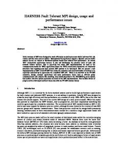
Figure 1: Diagram of a typical cable harness con guration and view of components in a bundle. leads to a natural decomposition of tasks and a taxonomy of design features. The structure and operation of the agents are discussed, along with such issues as managing the propagation of changes through the system and maintaining consistency when multiple versions of the design are present. Finally, we discuss general ideas drawn from this project for the development of computational systems for con guration design.
2 Cable Design Problem A large aerospace company selected cable design as an ideal area in which to introduce computational support for concurrent engineering. First, cable design is a relatively mature eld in which design requirements and constraints have been established over decades of practice. Second, cable design combines electrical and mechanical concerns and provides a motivation for integrating these disciplines. Cable routing also requires extensive three-dimensional spatial reasoning and can take advantage of recent developments in automated path planning. Finally, cable design stands to bene t dramatically from a simultaneous engineering approach, as the harness geometry, weight and cost are greatly a�ected by decisions made elsewhere in the organization. Figure 1 shows part of a typical harness used in satellites, missiles and air-
5 Est. Upstream design tasks (e.g., structural design, package design)
Configuration
Material Properties Real
Wire List Environment
Gross Path Planning
Constraints
$
Cost
Detailed Path Planning
Figure 2: Stages of the Cable Design Process craft. The cables come in many sizes and varieties and carry a combination of signals and power between electronic packages and subassemblies. Connectivity requirements determine the number of wires that each cable contains, which determines the bending sti�ness and mass distribution. The cables are held in place by clamps which ultimately de ne their paths. Special regions impose further design requirements. For example, a segment routed through a high temperature zone will require a thicker insulation jacket. Required o�sets or clearances for package maintenance and removal reduce the usable free space, whereas the presence of a exible obstacle (e.g. another cable) provides the nominal free space with some extensibility. The rule is that any electronic package or cable must be removable without disconnecting any other cable. Human factors are also considered; in areas near crawl spaces, a cable segment should not present a tempting \handle" for maintenance personnel to grab. The end result is that the cable and free space geometry become complex as large numbers of cables are squeezed into a minimum of unoccupied space. As for the overall design objectives, it is clear that for aerospace applications reliability is the governing imperative. However, harness weight and weight distribution are also critical factors, as they directly a�ect the performance of
ight vehicles. Finally, material and production costs are, as always, important considerations.
2.1 Cable design process
As mentioned in the Introduction, cable harness design is an example of \con guration design,\ in which there is a large search space of possible topologies and geometries. The large search space, along with the continual addition and deletion of constraints from related activities elsewhere in the organization, precludes searching for a globally optimal solution. The approach taken is therefore to decompose the design process into a series of partially decoupled activities as shown in Figure 2, which shows stages of the nominal cable design process
6 (manual or automated) and ow of information. The design involves iteration both within and among the tasks. Harness design begins with a set of electrical speci cations and environmental constraints. A \wiring-list" speci es the pin-to-pin connectivity requirements for electronic packages. Additional electrical speci cations may include the impedance and signal to noise ratio. Certain paths may be agged as critical at this time. The environmental speci cations include the geometric models of various packages and structural elements that make up the cabling environment, and the designation of special zones (e.g. high temperature, o�-limits). The remaining design steps are as follows: 1. Con guration selection | Once the electrical and environment speci cations are available, one must establish the basic harness con guration. The con guration determines how many trunks and branches the harness will have and in what order. The size of the search space becomes apparent when one considers that the number of possible con gurations grows factorially with the number of branches. Together, the harness con guration and the wiring-list determine the wire count in each branch of the harness. The wire count, along with information about wire gage, insulation and shielding type, later determines such properties as the minimum bend radius and weight and cost per unit length. 2. Routing | The next step of the design process is path planning, which is done in two stages to reduce the computational burden. The rst stage provides a rough estimate of the harness geometry to determine how well a given con guration \maps\ to the layout of the components being connected. Based on the outcome of this step, one may decide to proceed with detailed path planning, or try a new con guration. The re nement phase of path planning accounts for obstacles in the environment and constraints on minimum bend radius, etc. These constraints lead to a non-convex optimization problem in which one seeks to minimize a function of total harness weight and cost. 3. Part selection | Once the con guration and geometry are determined, components are selected from a catalog of wires, shielding, protective jackets, tubing, transition shells, connectors, ferrules and clamps. The catalog includes the weight, cost, and availability of each item. The selection is driven by the wire composition and the resultant size of each bundle, and is governed by a large set of selection rules. Considering that even a small harness contains over a hundred wires, it is clear that component selection can be time consuming. Moreover, as the nal cable properties (e.g. diameter, sti�ness, weight) can be determined only after these components are selected, it is likely that previous assumptions will be found invalid and iteration will be necessary.
7
2.2 Current practice
Today, cable harness design and fabrication involve a full-time sta� of 30 engineers at a large aerospace company. The designers are in continuous demand not only for developing new harnesses but also to respond to engineering changes on nished products and to produce special cables for testing, etc. Because the design process is time consuming, it is essential to begin early, when the electrical and geometric speci cations are incomplete. Speci cations are established through meetings among the cable designers, electronics designers, package designers, structural designers, and system analysts. Based on wiring schematics, two and three dimensional drawings, engineering lists, and meeting notes, the cable design sta� generate preliminary wiring lists, parts lists and schematic diagrams. Next, a mock-up of the cabling environment is constructed. Initially, the mockup consists of a crude collection of wooden blocks and cardboard boxes. More realistic models are used as the design progresses. The designers use hoses and cords of various diameters and bending characteristics to determine the cable paths and lengths. Once a suitable geometric solution is found, the components are selected with the aid of tables. The results are then entered into a database. Finally the design is transferred in the form of drawings, parts lists, and instructions to the production group, which generates its own production documents, programs the automated wire-routing and connectivity checking equipment, and builds the form (layout) boards and tooling. Large safety factors and loose tolerances are typically used so that project deadlines can be met. The design settles quickly on a single feasible solution because it is too costly to explore alternatives. Nonetheless, harnesses must often redesigned because almost every aspect of the design is directly dependent on upstream decisions. Even minor changes in electronics or placement and geometry of packages may necessitate a redesign.
2.3 Requirements for computational support
A review of the cable harness domain and the current practice lead to a set of objectives for computational support. It was decided that the computational system should: � Help people keep track of the interacting constraints. � Reduce tedium by automating routine aspects of the design process. � Provide numerical solutions to automate aspects of path planning that are today done ine�ciently and imprecisely with physical mockups. � Encourage experimentation with alternatives to achieve lower cost. � Reduce design cycle time.
8
C6
Figure 3: Three Main Perspectives �
Keep track of versions and facilitate re-use of previous design e�orts.
Super cially, the degree of interconnection among the subtasks in the cable design process and the desire to minimize overall costs would seem to motivate the development of a tightly integrated design system. However, practical concerns, such as system robustness, scalability and maintainability lead to the adoption of a loosely-coupled set of cooperating agents. Despite the attendant communications and storage overhead, we argue that this approach is more suitable for con guration design problems. Such issues will be discussed in more detail, following descriptions of the cable artifact and domain representation, the task decomposition and the agent interaction mechanisms.
3 Representations of Cable Domain Figure 3 shows three main perspectives associated with the cable harness representation. During product development, designers use multiple levels of abstraction to focus on di�erent aspects of the problem without being overwhelmed by detail.
9 C1
58
64
68
71
92
C6
C1
6 C2
C6
34
4
25
57
C3
C4
C5
C4
67
61 C6
C3
Base-Configuration
C5
C2
Wiring-List
(92-wire cable)
CABLE INTERFACE/ CABLE 1 FROM
C3
C4
TO
29
CONN-PIN CONN-PIN TYPE AWG CH
210-1 210-3
212-1 212-15
SS 24 TSP 24
+1 +2
210-5
213-6
TSP 22
+3
210-6
213-7
TSP 22
+4
210-11
212-17
TSP 24
+5
210-12 . . .
212-30
TSP 24
+6
C1
21 28 C5 C2
Figure 4: Wiring-speci cation and Cable Con gurations In computer-aided systems, features are an important mechanism for supporting abstraction. A criticism of feature-based design is that for novel designs, any set of features will be con ning unless the designer can de ne new features, or at least resort to primitive elements not in the feature set (Cutkosky and Tenenbaum 1990). However, in a domain such as cable harness design, which is a relatively self-contained and mature eld with de ned representations of both the design artifact and the environment, it is possible to build a complete \domain model\ of hierarchically organized features. This does not preclude the addition of new features if First-Link is expanded in the future, but it does require that any new features be integrated with the existing domain model. A wiring list for a small harness with six end connectors and 92 wires is shown in Figure 4. Three of the many con gurations that satisfy this speci cation are shown with the wire count indicated for each transition bundle. (End connector locations in these schematics have no correlation with locations in space.) Note that the wire-composition changes substantially between the con gurations.
3.1 Domain Model
The domain model in First-Link consists of a hierarchy of objects, divided into three main levels of abstraction.
10
1) aspects constitute the top of the hierarchy, and correspond to basic at-
tributes of a cable harness: electrical properties, con guration, and geometry (Figure 3). Similar needs for distinct representations of con guration and geometry have been identi ed in other domains by Welch and Dixon (1989) and Cutkosky, et. al. (1992). The electrical properties embody the primary function of the harness. Connectivity requirements are summarized in a wire list designating the originating connector and pin, destination connector and pin, wire type and gauge. Additional electrical speci cations concern impedance and shielding from external elds. The con guration de nes the harness as an assembly of elements, and is represented by a tree. When displayed graphically, it shows how the harness would look if spread out on a at surface, keeping all wires straight and all connections at right angles. Individual wires are grouped into bundles, with breakouts at transition points and connectors at the terminal nodes. Many con gurations are generally possible for a given set of electrical speci cations. For example, Figure 4 shows three con gurations that satisfy the same wire list. Associated with the con guration are rules for recomputing the wire count, diameter, weight per unit length, etc. for each bundle when the con guration is modi ed by merging, splitting or relocating branches. Finally, geometry de nes the space in which the harness resides, and the paths taken by the cables. It also includes the trajectories needed for installing and removing cables and other components. For a given con guration, many paths are possible within a free-space. The free space model is constructed from the boundary representations generated by a commercial CAD system. These are approximated with bounding boxes to form obstacles. The remaining free space is divided into small elements, called voxels, following the \approximate cell decomposition" method (Latombe 1991). In Figure 5, the representation of the cable harness and its environment is decomposed into several levels of abstraction, including basic aspects of the harness and high-level and low-level features. 2) domain-features are objects associated with each of the aspects that correspond to the main features in the domain. Most of the human interaction, as well as interactions among the agents, involves operations at the feature level. Figure 5 lists the most commonly used features in First-Link. 3) parameters are objects that constitute \slots\ in the domain-features. Computations at the parameter level are performed automatically by built-in methods (procedures) and rules. Examples include recomputing weight per unit length and bend radius, when the wire count changes.
11 Cable Model
Electrical Prop.
DOMAIN MODEL
Configuration
Geometry
ASPECTS C6
wiring list
config model
bundle properties
geometry model
path model
zone spec.
FEATURES
Length
Packages
High Temp.
Diameter
Structure
Off-Limit
Schematics Line Spec.
cable assembly
Stiffness
Free Space
Exposure
Min. R
Density
PARAMETERS
Parts Cable Spec.
Weight
Bundle Comp
Cost
Node Elem.
Path
Clamp Cfg. Virtual Cbl
Figure 5: Abstraction Layers In addition to the hierarchical relationships shown In Figure 5, there are many functional dependencies and constraints that are not inherited through part-subpart or class-subclass relationships. Figure 6 shows functional dependencies among domain parameters. As we shall see in the next section, both the hierarchical view of the domain model and dependencies such as those indicated in Figure 6 play a role in the choice of agents. Figure 6 shows some of the functional dependencies among design entities for cable harness design.
4
Task Decomposition and Agent Construction
4.1 Decomposition
Companies routinely rely on decomposition to overcome the complexity of large engineering tasks (Bond and Ricci 1991). A properly chosen decomposition allows high-level operations to be addressed somewhat independently from lowlevel details. For a computer-aided system, the decomposition allows people to work at a relatively high level, while low-level operations are performed in the background. Task decomposition is also a prerequisite for distributed problem
12
Geometry (Environment)
Zone Spec.
Wiring List Bundle
Composition
Bundle Diameter
Free Space
Bundle Stiffness Other Cables Bundle
Mass Density Path Configuration Model Parts List
Cable Cost
Clamping Configuration
Cable Weight
Virtual Cable
1st Order Effects Bundle Length
2nd Order Effects
Figure 6: Functional Dependencies
13 Domain Model
ASPECT x
ASPECT y
ASPECT z
F1 F2 F3 F4 F5
…
FN
b
a
Features
v
u
w AGENT 1
AGENT 2
AGENT 3
Figure 7: Agent Interactions solving and, in the case of First-link, leads directly to the chosen set of agents. Once a design process has been decomposed into tasks, and the dependencies among the tasks identi ed, a number of analysis methods can be applied to streamline the process (e.g., Steward 1981; Eppingeret al. 1991) to minimize delays and fully utilize available computational resources. However, the exercise of decomposing a complex engineering project into a set of tasks is challenging. In the case of First-Link, arguments and questions about the appropriate task decomposition far outnumbered those associated with the decomposition of the design artifact and environment into aspects and features. Figure 7 shows the e�ect of dependencies on agent interaction. Arcs u represent dependencies that do not require agent interaction. Arc v represents dependencies among high-level features, addressed e�ectively by agent interaction. Arcs w represent dependencies among low-level features associated with di�erent agents. While we cannot provide a general prescription for how to decompose design tasks, we observe that the following questions will tend to guide the process: How tightly coupled are the di�erent design activities? How closely synchronized must they be? Which activities can be performed in parallel and which must
14 be performed in series? The decomposition of tasks and formation of agents are ways to manage complexity, making the software system more modular and easier to maintain. The price paid for this decomposition, in comparison with a more centralized approach, is a lower bandwidth for sharing ne-grained information. The decomposition is ine�cient if two activities associated with di�erent branches of the hierarchy are richly connected with interdependencies at a ne grain (see arcs w in Figure 7), because all noti cations will have to be routed up through the agent/agent communications channel. By contrast, if the ne-grained interdependencies are mostly within a single branch of the hierarchy (arcs u in Figure 7) the decomposition functions e�ectively. The decomposition of design artifacts invariably accompanies that of the design process, and this raises additional issues concerning the agents. How similar are the design representations used for the di�erent activities? How large and how detailed a volume of information do they share? For example, engineers working on tolerancing and kinematic analysis of an assembly of components can take advantage of very similar representations (Cutkoskyet al. 1992); in this case it makes sense for them to operate on a single shared data structure. By contrast, the electrical and geometric aspects of a cable have little in common, although there are clearly some dependencies (e.g., path length a�ects cable resistance and capacitance).
4.2 Agent De nition
The de nition of an agent in the literature varies greatly, from those resembling automata (Genesereth 1989) to anthropomorphic versions (Sycara 1991; Werkman 1992). In First-Link, an agent is a software module that helps specialists work on one aspect of the design problem. The agents consist of three primary elements: (i) a local model and associated operations, (ii) interaction mechanisms, and (iii) a user-interface. The local model and interaction mechanisms are described in Section 5. Before proceeding to describe the agents, a few words about the user interface are in order. In the view of the authors, a task that lends itself to complete automation no longer quali es as design. The agents in First-Link therefore do not automate design; they assist designers by automating routine tasks and providing them with a graphic interface to support high-level operations such as experimenting with di�erent cable con gurations. In addition, they provide a convenient interface for inspecting and editing representations employed by the agent. This provision has been found essential for maintaining the con dence of the cable harness sta�, partly to make them feel that they are entirely in control and that no aspects of the agents' operations or data structures are mysterious.
15
4.3 First-Link Agents
First-Link currently comprises four agents for cable con guration management, 3D environment modeling, cable routing, and part-selection. 1. Cable Editor | Di�erent con gurations result in dramatically di�erent weights and costs. However, keeping track of the associated constraints and updating the a�ected parameters with each change is su�ciently tedious if done manually that designers are discouraged from experimenting. Consequently, the objective of the Cable Editor is to allow designers to test various con gurations rapidly, while automatically updating the details of the bundles and keeping track of constraints on maximum bundle diameter, etc. 2. Environment Editor | This agent is responsible for the generation and management of geometric entities (and their properties) within the cabling environment. The geometric information originates from external CAD systems. The Environment Editor assists users in constructing simpli ed solid models with convex polyhedra, and where adequate, bounding box primitives. Human guidance is important for e�ciently choosing bounding volumes. 3. Free Space Manager | The Free Space Manager (FSM) is the most computationally intensive agent. Its rst function is to generate a model of the available space for cable routing. It must also keep track of spaces that require special attention (e.g. high temperature zones). Based on a selected cable con guration, the FSM must then identify paths for each cable. The FSM begins by discretizing the free space into three-dimensional cells, or voxels. The path planning is done in two stages. First, an approximate path is generated. This path is collision-free, but does not take constraints such as minimum bend radius into account. The rough path permits an approximate cost estimate and may rule out certain con gurations from further consideration. If the rough path is satisfactory, detailed path planning is performed using either three-dimensional trajectory planning algorithms or energy-based methods (Conru and Cutkosky 1993). 4. Part Selector | The Part Selector is the only conventional expert system in First-Link. It uses the con guration (from the Cable Editor) to generate a parts-list. It maintains a library of part-numbers and part properties, such as weight and material cost. A rule base de nes the selection criteria. Adopting an incremental re nement approach, this agent tries at each stage to select as many parts as the existing information will allow. For example, if the length of a cable segment is not yet available, because the FSM has not yet applied the geometry constraints, the Component Selector uses a default (approximated) length. This agent also provides
16
DOMAIN MODEL AGENT
ASPECTS
AGENT MODEL
FEATURES …
BUILD
EXTRACT
AGENT MODEL IMAGE
MAP
Figure 8: Agent Model Image interactive tools that allow the user (or another agent) to override or modify the automatic component selection and provides a facility to annotate selections.
5 Agent Architecture and Interaction
5.1 Local (Agent) Model
Each agent contains an Agent Model, which consists of objects, rules and procedures. An agent-model for the Free-Space-Manager, for example, includes procedures and representations pertaining to the task of cable-routing. It also contains a set of graphical objects that display the resultant paths on the screen. Similarly, the agent-model for the Cable-Editor contains information for recomputing, manipulating and displaying the con guration. While parts of each agent model are of relevance only to the local agent, other parts correspond to features of the Domain Model discussed in Section 3, and are shared with other agents. The mechanism for extracting and exchanging these elements is through Agent Model Images (AMIs), which are composed of Feature Images (FIs) that correspond to features in the Domain Model.
17 In Figure 8 is a compact collection of data structures extracted from the Agent Model for transmission to other agents and for archival by the Central Node. Each agent has enough knowledge to rebuild its agent model from the associated image.
5.2
Mapping features between agents and the Domain Model
For each agent model image AMI (i.e. belonging to Agent Ai), there are n di�erent feature-images, fFI 1, FI 2, ..., FI g for a given design version, v. Thus, feature-image FI represents the jth component feature of an agent model A stored in a at data structure. A bidirectional mapping is used between the feature-images FI and the features of the Domain Model, F . Two threedimensional adjacency matrices capture the relationships among Agents (A ), Feature-Images FI's (FI ), and Domain-Features (F ). u is an operator that translates the value of kth domain-feature-image F into the jth feature-image that is used by the agent A . A non-zero value for u for some i, j, and k, indicates that FI is an input feature for local operations of A . Similarly, 8< 1 if no translation is required � ( ) = : 0 if the two features are independent translation operator indicates that g is an operator that generates a domain-feature F from FI A non-zero value for g identi es FI as an output feature of agent A . In most cases, the elements of the three dimensional arrays U and G take on the value of 1 or 0, but they can also be operators, T, that map a domain-feature into the corresponding feature-image, and vice versa. To determine which agent uses a given domain-feature F , one needs only to collect all non-zero elements u from the adjacency matrix U , where i
i
i
in
v
ij
i
ij
k
i
ij
k
ijk
k
i
ijk
ij
i
Fk
gkij
F Iij
where gkij
T
kij
ij
k
kij
ij
i
t
ijt
= any value; = g Similarly, to determine which agent a�ects or generates a speci c domainfeature F , one can look for all non-zero elements g from the matrix G , where Uk
� fuijk :
t
i; j
k
t
t
ijk
t
: = any value; = g A central node module, discussed in the next section, uses these matrices to notify agents of changes that a�ect them. This feature-mapping mechanism is a notable departure from First-Link's predecessor, Next-Cut (Cutkoskyet al. 1992), in which all agents operated directly on a single central model. The translation between the feature-images Gk
� fgkj
i; j
k
t
18 Global Evaluation
Local Synthesis
Domain Model
AMI
AGENT 1
DF's
…
Design Specification
Central Node
AMI Version Control
Local Storage
AGENT N
DF's
Local Storage
Central DB
Figure 9: First-Link System Architecture and the domain-feature-images, though seemingly arti cial when the \translation\ is just an identify, provides a layer of isolation and makes it easier to scale First-Link to larger problems and to distribute it over multiple workstations. To insure autonomy, we refrain from de ning a rigid format for the individual agent models and feature-images; these are best determined by the local activities. An Agent shares information with other Agents via components of an Agent Model Image (AMI), which are mapped to Domain Features (DF's). The Central Node provides a directory service and version control using RCS (Tichy 1985).
5.3 CENTRAL NODE
The Central Node is a collection of codes that support communication. One may view this module as an administration agent that is devoid of domain knowledge. The central node performs three main functions: 1) maintenance of the adjacency matrices, U and G; 2) provision of a directory service for interagent noti cations, mail and requests; and 3) version management of the various designs. A separate central module is used because we do not want each agent to keep track of which agents are on-line, and what each agent needs and generates. When an agent is added, only the central node needs to be updated. The
19 central node's roles as mail-handler and directory service also make it the logical candidate for keeping track of design versions and of the status of the design process. To add or remove agents, Connect(Disconnect)-Agent functions must be executed. One of the e�ects of these functions is to send a message to the central node about the agent's input needs and output capabilities (expressed in terms of the domain model) so that the central node can modify the adjacency matrices, U and G. First-Link therefore di�ers from a blackboard system (e.g., Hayes-Roth 1985; Nii 1986a; 1986b) in a couple of ways. First, the central node is not a repository of shared information, but merely a directory service|the information resides in the agent models, and features are extracted from these models for transmission to other agents. Second, agents do not broadcast unsolicited information to the central node for use in cooperative problem solving. The rami cations of this approach are considered in Section 6.
5.4 Inter-Agent Communication
The interaction mechanisms for agents in First-Link have been developed to meet the needs of human designers working on a collaborative project. For example, the agents must allow designers to work either independently or in groups or a combination of both. While working alone, a designer may want to test several what-if scenarios using only her local model, without invoking other designers. This temporary isolation postpones design propagation until the design meets local constraints, thus reducing backtracking. Once the design looks promising, is it made available to other designers for their input and analysis. Since in a distributed design environment the experts may not be available for immediate feedback, the agent interaction architecture must address the asynchronous nature of the design process. Mail is used as the medium of information exchange, since it is easily scaled and explicitly asynchronous. Mail is used to notify agents of new information, to request design components and their status from agents, and to send unstructured messages among people concerning unmodeled constraints, design reviews, etc. A list of mail messages also forms the basis of a work-list. The following section describes the coordination of mail messages. Figure 10 illustrates the mechanism of agent interaction. All communication is channeled through the central node. The asynchronous nature of the interactions, and the provision of version control (see Figure 9), make it possible for agents to work on di�erent versions of cable subsystems concurrently. For example, the Free Space Manager (FSM) in the upper left corner of Figure 10 is working on version 3 of cable design number 24. Its design feature inputs include \Con g List\, \Bundle Properties\, \Grid\, and \End Coords\ and its outputs include \Bundle Lengths\ and \Bundle Paths\. When an agent wants to publish a list of features (its AMI), a noti cation
20 is sent to the central node. The central node uses its U and G matricesto determine which agents use each of the features about to be published. For each of these agents, a list of the names of the altered features is sent via mail under the header, \Notify.\ Each a�ected agent can then act on the mail at its leisure. Exactly how the publish and retrieve works depends on the implementation. On a single-workstation system, it is e�cient for agents to read and write published features (the AMI's) to and from a shared directory. In a distributed implementation, the AMI le is sent with the mail noti cation | e.g., via Servicemail, (Glicksman 1991). In either case, the basic publishing concept is the same. First-Link was originally implemented on a single workstation. The directory and dispatch mechanism for the mail has recently been revised using DIS (Distributed Information Service) (Glicksman 1991) to formalize the mail service functions with DIS tools, and to extend the architecture so that agents can easily reside on multiple workstations. Future work will exploit additional capabilities of DIS, as discussed in Section 6.6. Figure 10 shows the agent interaction mechanism and feature mapping. The central node maintains a directory of \suppliers\ and \users\ of information and the feature mapping relations, and keeps track of which agents are on-line. Agents can work asynchronously and on di�erent design versions at the same time. An agent can obtain new versions of features either indirectly, in response to a noti cation message from the central node, or directly, by invoking the central node's retrieval mechanism. In either case the retrieval mechanism is called with the design feature's name, the requesting agent's name, the cable design ID, and the version ID. An optional publishing-agent parameter is de ned to specify where the data is located. If a publishing agent is not de ned, the retrieval mechanism uses the directory of the central node to determine which agent(s) can supply the needed feature. Once the creator (publishing) agent is determined, the retrieval mechanism obtains the requested information from that agent. If the information is not immediately available, the requesting agent is prompted to decide if a request should be sent. This \Request\ message contains the feature name, cable design ID, version ID, and requesting agent's name. It will provoke new computations on the part of the supplier agent. As the supplier agent publishes the requested information, the request messages are removed from its queue. Before leaving this section, it should be pointed out that while noti cations are automatic, the decision to respond to a noti cation, or to process a queue of noti cations and requests for an agent that has just been brought on-line, is under manual control. This is in contrast to research systems like Next-Cut (Cutkoskyet al. 1992) that propagate all changes immediately and automatically. The semi-automatic approach taken in First-Link grew out of discussions with engineers working on cable harness design | they preferred (i) to work
21
A3: Free Space Manager (FSM)
FI3j = u3jkFk
A2: Cable Editor (CE) Cable 2
Cable 24
Fk = gk2jFI2j
Config List
Wire List
File
Bundle Len.
Bundle Props. Grid
Vers. 1
End Coords.
Config List
Central Node
Vers. 3
AMI
Bundle Len. Bundle Paths
Bundle Props.
Directory
Makes
Config List
CE
Bundle Props. CE
FILE
AMI
Uses
Config Model
FSM PS FSM
Bundle Len.
FSM
PS CE
Grid
EE
FSM
A1: Env. Editor (EE)
Config Model
CE
PS
Cable 2
End Coords.
EE
FSM
FILE
A4: Part Selector (PS) Cable 4 Config Model Bundle Len.
Environment
File Bundle Props.
Vers. 1
AMI
Design Feature
Grid
Mail & Data Transfer
End Coords.
Local Save & Load
Vers. 6 Cost/Weight Parts List
FILE
FILE
Figure 10: Agent Interaction Mechanism
AMI
22 asynchronously, \checking in\ and \checking out\ at will, and (ii) to be in full control of the propagation of changes across agents.
5.5 Version Control
Version control in First-Link is performed using two identi cation tags: a cable identi cation number, and a version number. Together, these form a unique design ID. The cable ID corresponds to the identi cation given to each wiring speci cation, which will ultimately result in a unique cable within the system. The version ID is used to store snapshots of the design, to mark signi cant design stages for the purpose of backtracking. At any time, agents can work on multiple designs. It is the function of the central node to maintain the latest version number and the location of each design component. The version management is built on a standard check-in and check-out concept (RCS) (Tichy 1985). Any time an agent publishes a new set of feature-images, the adjacency matrix maps them into the corresponding domain-features. This invokes the RCS check-in command, where the contents of the new feature are matched to the cable ID and then compared with the last version of that feature. If there is a change, then the central node assigns a new version number. When an agent requests a speci c domain-feature, the latest version with the same cable ID is \checked-out," unless the agent requests an older version explicitly. This way, the central node insures that each agent works on the most recent data. Independent of version control for the overall design, individual agents can store feature-image sets fFI g and maintain a local revision control system. This is not required by the system architecture, but may can be useful for backtracking and design reuse at the local agent-level. This version control approach resembles the distributed revision control methods proposed for concurrent engineering environments (Sriramet al. 1992). However, unlike systems for which complete copies of the central model are stored at each local node, the First-Link system stores only the local featureimages at each node. Duplication is minimized, as the agent models are intrinsically complementary. Furthermore, the task decomposition results in individual agent models that are fairly self-contained. ij
6 Discussion The development of the First-Link system produced useful insights that are applicable in other problem domains. These are considered in the remaining paragraphs.
23
6.1 Problem Characterization
Con guration design problems poses special challenges for computational support. These are problems with large spaces and many interdependencies among tasks and design factors. Human participation is essential for navigating the search space. However, the human ability to make wise decisions deteriorates rapidly with the number and complexity of the interdependencies. One way to overcome the complexity is to ignore the interdependencies during the estimation phase of the design, thereby serializing the process (Eppingeret al. 1991). However, the e�ects of committing to an inferior design decision generally do not surface until much later in a downstream step, at which point the desired modi cations must now be weighed against the cost and the delay of these changes. Still, this is the most commonly applied solution for handling complexity in the industry because humans (and human organizations) are inherently limited in their capacity to deal with many interacting factors. If a computational support system can extend this capacity, there are clear bene ts to addressing the interdependencies early in the design process. This is the basis of concurrent engineering. Simply applying sophisticated computer tools is not enough. A group of powerful tools may indeed be integrated into a large, and e�cient, decision support system. But this approach is viable only if the problem domain is static|i.e., the tools, design rules, and production process do not change over the product life-cycle. But many products have life-cycles measured in decades. Earlier e�orts to implement monolithic systems often failed, because they could not be adapted economically to the changing needs.
6.2 Bene ts of Agent-Based Approach
The agent-based approach is an e�ort to manage simultaneously the complexity of the problem and the transitory nature of the necessary design support systems. We shall elaborate on why it is worthwhile to incur the extra communications and storage overhead associated with agents, including the need for mail systems, messages, directories, noti cation, and extraction of AMIs from detailed models. In comparison with conventional approaches, the advantages are two-fold:
Distributed design support: In large projects, the various activities and
their corresponding computational tools may best be located at di�erent places. The agent architecture places no restriction on where individual agents should reside. (For instance, the Free Space Manager could reside at the physical mock-up facility, while the Part Selector could be installed at the part storage location, without structural modi cation to the FirstLink system.) Furthermore, the system continues to function if an agent goes o�-line.
24 DM CE
EE F
FSM
PS
Next-Cut Procedural Systems
Traditional BBS's
Centralized Approach
• • • • ❏ ❏
shared variables efficient requires complete knowledge difficult to reconfigure
First-Link
G
Distributed Approach
PP
CM AA
PACT
FA TA
• • • •
suitable for routine or parametric design high bandwidth
❏ ❏
dispatch-based information transfer large overhead requires minimum domain knowledge easy to reconfigure necessary for new product design low bandwidth
Figure 11: Categories of Computational Cupport Systems
Ease of maintenance and adaptation: It is expected that the design issues,
tools and methods will change over time. Large, tightly integrated software packages are notoriously di�cult to maintain and modify under such circumstances. The First-Link architecture allows new agents to be brought on-line with relatively little di�culty| at most, the domain model must be augmented to accommodate the concerns of the new agent.
6.3 Agent Selection
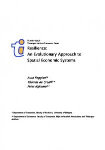
In conjunction with the task-decomposition, and the representation of the design artifact, the selection of agents is guided by an underlying assumption that the interdependencies among parameters belonging to two di�erent agents are few, weak, or preferably both. It is assumed that interactions may therefore be treated su�ciently by exchanging high-level features (via feature-image fFIg structures). Excessively frequent exchange of the FI's, accompanied by translation activity within each agent, is an indication that the de nition of the agents should be reviewed. As shown in Figure 11, the categories of computational support systems range from centralized systems to highly distributed, asynchronous ones. The
25 desired degree of autonomy of subsystems determines the suitable system architecture.
6.4 Autonomy of Agents
Agent-based systems vary, depending on the extent of autonomy imparted to the agents. As Figure 11 shows, First-Link is part way along a spectrum of possible approaches. The predecessor of First-Link was a mechanical design system called Next-Cut (Cutkosky and Tenenbaum 1991). In Next-Cut, the agents relied on a common data format and freely accessed a central model. Accordingly, the agents depended heavily on the system implementation and had little autonomy. At the other extreme are architectures such as those associated with PACT (Cutkoskyet al. 1993) and Carnot (Collet, et. al. 1991) systems. These systems promote total autonomy. Here, no predetermined, domain-model is assumed, and the cooperation of agents results from ontological commitments associated with the design domain. Which architecture is suitable for a problem depends on the availability and transience of the domain knowledge. We o�er the following comparisons. For novel design problems an overall view of the design model and the decomposition of design tasks is rarely available, at least at the outset. In such cases, establishing the interdependencies and areas of shared concern is of primary importance. As an example, in the case of the PACT system, where a new design team is being formed from existing agents and services on a network, it is necessary for agents to post assertions of interest, which are then routed by facilitators to other agents that may be able to provide the desired information. Thus, the design team evolves organically. In PACT there is a priori no global view of the design or design process. PACT is a federation with truly distributed knowledge. By contrast, in First-Link we begin with a comprehensive design model. It is assumed that all the team members and main areas of concern are known before hand. This is not to say that a new agent cannot be added to the system to address new issues. However, if such an agent is added, changes to the overall design representation must be made. (In contrast, in the PACT solution the new agent is simply brought on-line and starts broadcasting assertions of interest and responding to any other requests that it can accommodate.) Because an overall view of the design domain and the task decomposition is available, the focus in a con guration design can shift toward optimizing the design process, a process for which the methods of Steward (Steward 1981) and others (Eppingeret al. 1991; Krishnanet al. 1992) are applicable. The First-Link approach is consequently less exible than an undirected broadcast system but potentially more e�cient, because task planning and optimization can be done ahead of time based on the known dependencies among design tasks and variables. In essence, cable harness design can proceed under a closed-world assumption | we know the domain model and the potential users and suppliers of information.
26 At the other end of the spectrum are centralized systems like First-Link's predecessor, Next-Cut. In Next-Cut, all agents ran on a single workstation and shared a single hierarchical representation of the evolving design and associated manufacturing plans. There was no concept of detailed local models from which abstract models were extracted to share with the other agents and no provision for having agents work on di�erent versions at the same time. Instead, every agent operated directly on the central design representation, which was understood to represent the current version. Changes were propagated immediately and automatically. There was also little provision for allowing individual agents to go o�-line for any length of time. The remaining agents could continue to function in their absence but there was no spooling of noti cations and requests. As a consequence, Next-Cut was ill-suited to the needs of a team of collaborating engineers, working on di�erent workstations and with di�erent job schedules.
6.5 Human Participation
In the construction of First-Link, human interaction was stressed for two reasons: (1) because it is impossible to capture all the case-speci c rules and constraints that may apply to a particular design, and (2) because computer programs cannot yet handle NP-complete problems e�ciently without human guidance. In contrast to routine analysis, design problems begin with speci cations that are largely subjective. The number of design parameters is large, and changes over time, as new desirable qualities of the product are \discovered,\ and new features and characteristics are added. It is necessary to recognize that the very decomposition of a design problem into layers of features and tasks is a subjective process. Therefore, it is essential that the designer be given freedom to apply his creative and intuitive capacity to expedite the design process, including the power to modify and override solutions suggested by the system. The fundamental function of the First-Link agents is not to automate, but to enumerate, clarify, and resolve the options that the designer has at each stage. The agents recommend potentially acceptable solutions based on their limited criteria. (This is apparent, for instance, in the Free Space Manager's initial selection of a feasible cable path.) The agents are designed to detect and ag situations where the designer has made an (apparent) blunder; for example if the designer selects a con guration that violates the minimum-bundle-size constraint. Even then, the designer has the option to override the warning after recording a justi cation. For example, he may chose to override the constraint because he knows it will probably become inactive as a result of subsequent design changes. In this way, the designer can use his or her high-level knowledge of the design process, or of the nature of a speci c case (e.g., how constraint-bound), to expedite the design.
27
6.6 IMPLEMENTATION ISSUES
Two aspects govern the scalability of a system like First-Link: (i) communications overhead, and (ii) the complexity and number of active agents. For a single workstation system, the available memory and CPU time are the limiting factors; for a distributed system, data ow restrictions and network throughput become important. First-Link has been tested as both a single-user, single-host system and a multi-user, multi-host system. In either case, agents can communicate with each other via pointers to mutually accessible directories on a LAN, or by transferring
at les. While the former is preferable, this may not be possible or e�cient if the design e�ort is distributed geographically. When testing First-Link on a single host, we used a 12 mips workstation with 36 megabytes of RAM, running a CLOS-based object environment. In a typical design session involving one section of the cabling environment and a six-connector cable harness with associated components, paths, etc., the four agents generated approximately 630 objects. The total image size for the system, including the programming environment, and the user-interface was about 51 megabytes. Based on the current CPU and memory use, we estimate that 200% increase in size of the program will cause no performance problems. Of course, distributed processing leads to proportionally greater computing and memory capacity and thus can handle much larger problems requiring tens of thousands of objects. Whether implemented on a single workstation or on multiple workstations, the size of the adjacency matrices for maintaining the dependency information grows as a product of the number of agents and the number of domain features. For very large design problems (e.g., aircraft or ship design), the approach taken in First-Link is likely to be inadequate. However, even for a problem involving dozens of agents (the foreseeable upper bound for cable design problems, including links to structural and electronic package design organizations), the amount of time needed to search and operate on these matrices will be on the order of seconds and will be negligible compared to computation times on the order of minutes needed for path planning. Moreover, the communications complexity does not actually grow as rapidly as the number of agents squared because not all agents interact with each other (especially when there are many agents) and because the number of domain features grows as the union rather than the sum of the features associated with all agents. For example, in initial experiments First-Link has employed four agents, with approximately ve high-level features per agent. However, the number of high-level features in the domain model was nine, rather than twenty. More complex aspects of coordination, such as automatic constraint propagation, con ict detection and resolution, etc. will clearly increase the complexity of the overall system, and these are subjects reserved for future publications. At the time of this publication, First-Link remains primarily a research
28 testbed. However, preliminary assessment has indicated that the system is readily accepted by sta� engineers and that it can signi cantly reduce overall design time. For example, given a harness con guration, the task of assessing the properties of the bundles (wire count, bend radius etc.) and selecting all the necessary components today consumes one or two days when done manually. Using the Cable Editor and Part Selector agents (the two agents that are most mature) the same results are obtained in about one minute.
6.7 Future tasks
Further work on several areas is now in progress:
6.7.1 physical distribution of agents:
The architecture of First-link system enforces complete modularity of agents, thus allowing the implementation to vary freely with respect to the physical location of agents. However the original implementation of First-Link system was done on a single workstation. As mentioned in Section 5.4, we have recently implemented a physically distributed version using DIS (Glicksman 1991). DIS provides various tools including (1) a directory service, (2) access control and authorization, and (3) system encapsulation. Future plans will take advantage of these tools to construct additional collaboration facilities, such as distributed version control.
6.7.2 design decision support and coordination:
First-Link's modular approach accentuates the need for a dynamically updated global view of the design process. To this end, the domain model is being incorporated into a design process evaluation tool which, we hope, will help the designer predict the e�ects of design decisions before committing to them. As a rst step, we are classifying types of dependency relations among design entities and operations, and determining what kinds of analysis can be performed on the resulting graphs. We are presently exploring a decision support system called Redux (Petrie 1992) for managing dependencies. Redux complements the DIS message handler and will eventually assist in the coordination of multiple activities. We will further combine REDUX with a constraint management module for con ict detection and resolution among the First-Link agents. The issue of coordination is closely related to more sophisticated version control schemes, when there are multiple agents with the ability to produce the same, or broadly overlapping, outputs. In such circumstances, the simple RCS check-in check-out approach becomes inadequate. Approaches such as those described in (Kaiser, et. al. 1988) for large teams of programmers working on parts of the same software, become desirable. We believe that the Redux system will provide the rationale and dependency book-keeping needed for this task.
29
6.7.3 integration with upstream/downstream activities:
At present, First-Link receives electrical and geometric speci cations from upstream design activities (e.g., vehicle structural design) but does not communicate requests or noti cations upstream. This capability will be added in the future, starting with the ability to transmit electronic messages containing annotated geometric entities (e.g., a geometric model and text description of a suggestion for relocating an electronics package). Better integration with the manufacturing stage is also underway. A Production Planner agent will incorporate the production rules and requirements once a cable is designed. A core model for this agent already exists in the form of an external expert system, to which First-Link currently transmits its results via electronic mail.
6.7.4 additional agents:
Additional agents will presently be added to the four that constitute First-Link. A cable simulation agent will allow the designer to observe the behavior of a cable under as-installed conditions. This agent will gather its input from the other agents to display the computed bending properties, and will enable the designer to select the clamping con guration of each bundle. When a space must be shared by several cable bundles, this agent will also help determine how much space can be created by pushing other bundles aside. A Cost Comparator agent will expand on the current capacity of the Part Selector to estimate the cumulative costs of production, installation, and maintenance, based on cost models at the sponsoring company.
7 Acknowledgment This work has been supported by Lockheed Missiles & Space Co. and DARPA under ONR grants N00014-88K-0620 and N00014-92-J-1833.
8 References Bond, A. H. and R. J. Ricci 1991. Collaboration in Aircraft Design. Computer-Aided Cooperative Product Development. D. Sriram and R. Logcher, ed. New York: Springer-Verlag. 152-182. Collet, C., M. N. Huhns and W.-M. Shen 1991, December. Resource Integration Using a Large Knowledge Base in Carnot. IEEE Computer , 55-62.
30 Conru, A. and M. Cutkosky 1993. Computational Support for Interactive Cable Harness Routing and Design. Technical Report 19930919. Center for Design Research, Stanford University. Cutkosky, M., R. Engelmore, R. Fikes, T. Gruber, M. Genesereth and W. Mark 1993, January. PACT: An Experiment in Integrating Concurrent Engineering Systems. IEEE Computer, special issue on Computer Supported Concurrent Engineering 26(1), 28-37. Cutkosky, M. R., D. Brown and J. M. Tenenbaum 1992. Working With Multiple Representations in a Concurrent Design System. The ASME Journal of Mechanical Design 114(3), 515-524. Cutkosky, M. R. and J. M. Tenenbaum 1990. A Methodology and Computational Framework for Concurrent Product and Process Design. Mechanism and Machine Theory 25(3), 365-381. Cutkosky, M. R. and J. M. Tenenbaum 1991. Providing Computational Support for Concurrent Engineering. International Journal of Systems Automation: Research and Applications 1(3), 239-261. Eppinger, S. D., D. E. Whitney, R. P. Smith and D. A. Gebala 1991. Organizing the Tasks in Complex Design Projects. Computer-Aided Cooperative Product Development. D. Sriram and R. Logcher, ed. New York: Springer-Verlag. 229-252. Genesereth, M. 1989. A Comparative Analysis of Some Simple Architectures for Autonomous Agents. Technical Report Logic-89-2. Logic Group,
Computer Science Dept., Stanford Univ.
Glicksman, J., B. L. Hitson, J. Y.-C. Pan and J. M. Tenenbaum 1991. MKS: A Conceptually Centralized Knowledge Service for Distributed CIM Environment. Journal of Intelligent Manufacturing 2(1), 27-42. Gruber, T. R., J. M. Tenenbaum and J. C. Weber 1992. Toward a Knowledge Medium for Collaborative Product Development. Arti cial Intelligence
31 in Design, J. S. Gero, ed., Pittsburgh, Kluwer Academic Publishers, 413432. Hayes-Roth, B. 1985, A Blackboard Architecture for Control. Arti cial
Intelligence 26, 251-321.
Kaiser, G. E., P. H. Feiler and S. S. Popovich 1988, May. Intelligent Assistance for Software Development and Maintenance. IEEE Software , 40-49. Krishnan, V., S. D. Eppinger and D. E. Whitney 1992. Ordering CrossFunctional Decision Making in Product Development. WP 3299-91 MS. Massachusetts Institute of Technology. Latombe, J. C. 1991. Robot Motion Planning. Boston, MA: Kluwer Academic Publishers. Lu, S. C.-Y. 1992. Knowledge Processing Tools for Concurrent Engineering Tasks. Proceedings of the 2nd International Conference on Automation
Technology, 37{46.
Nii, H. P. 1986, Summer. Blackboard Systems: Blackboard Application systems, blackboard systems from a knowledge engineering perspective. The AI Magazine , 82-106. Nii, H. P. 1986, Summer. Blackboard Systems: The Blackboard Model of Problem Solving and the Evolution of Blackboard Architectures. The AI Magazine , 38-53. Pan, J. Y.-C., J. M. Tenenbaum and J. Glicksman 1989. A Framework for Knowledge-Based Computer-Integrated Manufacturing. IEEE Transaction on Semiconductor Manufacturing 2(2), 33-46. Park, H., S.-H. Lee and M. R. Cutkosky 1992. Computational Support for Concurrent Engineering of Cable Harnesses. Computers in Engineering,
32 San Francisco, August, ASME, 261-268. Petrie, C. 1992. Constrained Decision Revision. Proceedings of the 10th National Conference on Arti cial Intelligence (AAAI-92), 393-400. Sriram, D., R. Logcher, A. Wong and S. Ahmed 1991. An Object-Oriented Framework for Collective Engineering Design. Computer-Aided Cooperative Product Development. D. Sriram and R. Locher, ed. Springer-Verlag. 51-92. Sriram, R., B. K. Livezey and W. A. Perkins 1992. A Distributed Shared Database for Concurrent Engineering. CE & CALS Conference, Washington, 27-43. Steward, D. V. 1981. The Design Structure System: A Method for Managing the Design of Complex Systems. IEEE Transactions on Engineering Management EM-28, 71-74. Sturges, R. H. 1992. A computational model for conceptual design based on function logic. Arti cial Intelligence in Design, J. S. Gero, ed., Pittsburgh, Kluwer Academic Publishers, 757-772. Sycara, K. P. 1991. Cooperative Negotiation in Concurrent Engineering Design. Computer-Aided Cooperative Product Development. D. Sriram and R. Logcher, ed. New York: Springer-Verlag. 269-297. Talukdar, S. N., P. S. deSouza, R. Quadrel and V. C. Ramesh 1991. ATeams: Multi-Agent Organizations for Distributed Iteration. EPRI/NSF
Workshop on Application of Advanced Mathematics to Power Systems.
Tichy, W. F. 1985, RCS{A System for Version Control. Software-Practice & Experience. 15(7), 637-654. Welch, R. V. and J. R. Dixon 1989. Extending the iterative redesign model to con guration design: sheet metal brackets as an example. Design theory
33 and Methodology - DTM 1989, Montreal, Quebec, CANADA, ASME, 8188. Werkman, K. J. 1992. Multiple Agent Cooperative Design Evaluation Using Negotiation. Arti cial Intelligence in Design, J. S. Gero, ed., Pittsburgh,
Kluwer Academic Publishers, 161-180.