An Agent Modeling Language Implementing Protocols through Capabilities Nikolaos Spanoudakis1,2 1 Technical University of Crete, Greece
[email protected]
Abstract In this paper we present how to use the Agent MOdeling LAnguage (AMOLA) to define agent interaction protocols and how to integrate these in an agent model. AMOLA provides the syntax and semantics for creating models of multi-agent systems covering the analysis and design phases of a software development process. It supports a modular agent design approach and introduces the concepts of intraand inter-agent control. The first defines the agent’s lifecycle by coordinating the different modules that implement his capabilities, while the latter defines the protocols that govern the coordination of the society of the agents. The modeling of the intra and inter-agent control is based on statecharts. The analysis phase builds on the concepts of capability and functionality. AMOLA deals with both the individual and societal aspect of the agents showing how protocols and capabilities can be integrated in agents design.
1. Introduction One of the major issues in Agent Oriented Software Engineering (AOSE) is the modeling, representation and implementation of agent interaction protocols. A wide range of methodologies for AOSE either adopt one existing model (most usually AUML), while others either employ UML models (like activity diagrams) or do not address the issue and just define messages that the agents send to each other (allowing the modeling of simple protocols). In this paper, we use a familiar language, the statecharts modeling language [3] for designing agent systems. It is not the first time that statecharts have been used for modeling agent communication protocols, however, it is the first time that they are used inside a software development methodology in such a way that protocols can be seamlessly integrated with the other capabilities of an agent. We use the concepts of capability and functionality to show how involved
Pavlos Moraitis2 2 Paris Descartes University, France
[email protected]
actors can reach their goals, thus aiding system analysis. In [7] we introduced the Agent Systems Engineering Methodology (ASEME), a complete software development process that reuses successful practices in the literature and introduces a new language, the Agent Modeling Language (AMOLA) for modeling agent systems [8]. The Agent Modeling Language (AMOLA) describes both an agent and a multi-agent system. It defines the concept of capability as the ability of an agent to achieve specific tasks that require the use of one or more functionalities. The latter refer to the technical solution(s) to a given class of tasks. Moreover, capabilities are decomposed to simple activities, each of which corresponds to exactly one functionality. This paper builds on the work of Moore [5] and shows how agent interaction protocols are modeled in AMOLA, using the inter-agent control model, and how they are integrated in the intra-agent control model when building agents as a set of capabilities. In section 2 we present the analysis phase models and in section 3 we present how they are transformed to design phase models and the information inserted at that phase. We conclude in section 5.
3. The Analysis Phase Models The main models associated with this phase are the use case model, the agent interactions protocol model and the roles model. The first is an extended UML (Unified Modeling Language) use case diagram and the last is mainly inspired by the Gaia methodology [9] roles model. The use case diagram helps to visualize the system including its interaction with external entities, be they humans or other systems. Agents are modeled as roles, either within the system box (for the agents that are to be developed) or outside the system box (for existing agents). Human actors are also represented as roles outside the system box with their name written in italics. The different use cases must be directly related
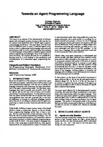
to at least one artificial agent role. These general use cases can be decomposed to simpler ones using the include use case relationship. Based on the use case diagram the system modeler can define the agent interaction protocols and roles models. A use case that connects two or more (agent) roles implies the definition of a special capability type: the participation of the agent in an interaction protocol. For the AMOLA models demonstration we present the analysis and design models for a meetings management system as it has been widely used in the past for demonstrating the use of methodologies (e.g. using the Prometheus and MAS-CommonKADS methodologies in [4]). This system’s requirements, in brief, are to support the meetings arrangement process. A user declares his wish to schedule a meeting (or reschedule an existing one) and the system, knowing the users’ schedules and preferences, services the user’s requests and organizes the meeting aiming to maximize overall user satisfaction. In the Analysis phase we have the use case diagram presented in Figure 1. The number of actors of the same type participating in a use case is indicated on the line connecting the use case to the actor. It is one, if the line connecting the use case to the actor has no indication. In our example, all use cases are one to one except for the “negotiate meeting date” use case that requires a meetings manager participant and two or more personal assistants.
Figure 1. Use case diagram Then, we define the agent interaction protocols. Such are all the use cases that connect two or more agent roles. These use cases must be refined to simpler ones that correspond to elementary tasks. For example, in Figure 1, the “request new meeting” use case is refined for the “Personal Assistant” actor to the simple tasks “send new request” and “receive new results”. In Figure 1 we have five general use cases that correspond to the goals of the requirements analysis phase – however, this phase is out of the scope of this paper (the reader should consult [7] for more information) – and the two aforementioned simple use cases. The general use cases are transformed to agent capabilities. The included (simple) use cases, which represent
simple tasks, are transformed to activities in the agent interaction protocol Process field. In Table 1 we present the “Negotiate meeting date” agent interaction protocol definition. It defines two roles, i.e. Personal Assistant and Meetings Manager, the rules for engaging (why would they participate in this protocol), the outcomes that they should expect in successful completion and the process that they would follow in the form of a liveness formula. The liveness formula is a process model that describes the dynamic behavior of the role inside the protocol. It connects all the role’s activities using the Gaia operators [9]. The liveness formula defines the dynamic aspect of the role, that is which activities execute sequentially, which concurrently and which are repeating. Table 1. Agent interaction protocol Negotiate meeting date Participants
Personal Assistant
Meetings Manager
Rules for engaging
He needs to create or participate to a meeting
He has a meeting with more than one participants that has no date assigned to it
Outcomes
He has scheduled participation to a meeting
He has arranged a meeting that met all the participants needs
Process
negotiate meeting date = receive proposed date. (decide response. send results. receive outcome)+
negotiate meeting date = (decide on date. send proposed date. receive results)+. send fixed date.
Then we define the role model for each agent role. To build the roles model we add the interaction protocols that this agent will be able to participate in. We continue with the definition of the liveness model inside the roles model. The liveness model has a formula at the first line (root formula) where we can add capabilities. A capability must be decomposed to activities in the following line. Figure 2 shows the role model for the Personal Assistant role including six liveness formulas. The last imports the part in italics from the Personal Assistant’s Process of the “Negotiate meeting date” agent interaction protocol (as it was presented in Table 1). Note that the role imports the liveness formulas from the agent interaction protocol model for each protocol that it participates. The elements (i.e. capabilities or activities) of these formulas are integrated in the liveness formula of the role model. So there is an interleaving among the capabilities or activities imported by the protocol and those defined directly at the role level. Moreover, the analyst can
refine the protocol formulas (if they are too general) so that the agent role successfully implements his use cases. However, the modifications that the analyst is allowed to do is to add new activities that make the bridge between the activities of the role and those imported by a protocol and/or to refine an activity to more specific ones (i.e. add a new formula to define more detail in a protocol activity). The analyst, in our example, has added the activity “update schedule” to the “negotiate meeting date” formula (see the last liveness formula in Figure 2 that expands the Personal Assistant’s Process depicted in Table 1). Role: Personal Assistant Protocols: Negotiate meeting date: personal assistant Request change meeting: personal assistant Request new meeting: personal assistant Liveness: personal assistant = (service user. learn user habits)ω || (negotiate meeting date)ω service user = get user request. (read schedule | request change meeting | request new meeting). show results learn user habits = learn user preference. update user preferences request change meeting = send change request. receive change results request new meeting = send new request. receive new results negotiate meeting date = receive proposed date. (decide response. send results. receive outcome)+. update schedule
Figure 2. The Personal Assistant role model Finally, the activities are associated to generic functionalities which correspond to the technologies that will be used for realizing them (see Figure 3). The reader should note that a special capability not included in the use–case diagram named communicate appears. This capability includes the “send message” and “receive message” activities and is shared by all agents and is defined separately because its implementation is relative to the functionality provided by the agent development platform, e.g., in our example, JADE (Java Agent Development), an open source agents development framework that adheres to the FIPA (Foundation for Intelligent Physical Agents) standards.
Figure 3. Capabilities, activities and functionalities
4. The Design phase Models The models associated with the Design phase are the inter-agent control and intra-agent control. They define the functional and behavioral aspects of the multi-agent system. For the Design Phase models we use the language of statecharts as it is defined in [3]. Statecharts are based on an activity-chart that is a hierarchical data-flow diagram, where the functional capabilities of the system are captured by activities and the data elements and signals that can flow between them. The behavioral aspects of these activities (what activity, when and under what conditions it will be active) are specified in statecharts. There are three types of states in a statechart, i.e. OR-states, AND-states, and basic states. OR-states have substates that are related to each other by “exclusive-or”, and AND-states have orthogonal components that are related by “and” (execute in parallel). Basic states are those at the bottom of the state hierarchy, i.e., those that have no substates. The state at the highest level, i.e., the one with no parent state, is called the root. Each transition from one state (source) to another (target) is labeled by an expression, whose general syntax is e[c]/a, where e is the event that triggers the transition; c is a condition that must be true in order for the transition to be taken when e occurs; and a is an action that takes place when the transition is taken. All elements of the transition expression are optional. The scope of a transition is the lowest ORstate in the hierarchy of states that is a proper common ancestor of the source and target states of the transition. Multiple concurrently active statecharts are considered to be orthogonal components at the highest level of a single statechart. Events that can trigger a transition can be an incoming (or perceived) inter-agent message, an event generated by any other executing agent activity in the scope of the transition, or the ending of the executing state activity. The latter case is also true for a transition with no expression. Finally, each state automatically starts its activity on entrance. We define the inter-agent control by transforming the agent interaction protocols of the analysis phase to state diagrams. A state diagram is generated by an initial state named after the protocol. Then, all participating roles define AND sub-states. The right hand side of the liveness formula of each role is transformed to several OR-states within each ANDstate by interpreting the Gaia operators in the way described in Table 2. The items that the designer must add at this phase are the data structures used for defining the protocol
parameters, the timers (defined as in [2]), the message types and, finally, the conditions for each transition. The resulting statechart is depicted in Figure 4. At this point the reader should notice the differences with Moore’s proposal ([5]). All states represent activities, while in his work they just represent a point in time where a condition is true (like in finite state machines). The preconditions of the agent interaction protocol become the conditions of a source-less transition that targets the first state of the protocol for each role. The transition will be connected to a source state in the intra-agent control model. The preconditions for the meetings manager role, which have been described in free text in the agent interaction protocol model (see rules for engaging in Table 1), concern the arrangement of a meeting with a list of more than one participants. They become the conditions for the decide on date state and can be formally expressed by the atoms hasToArrange(m, meeting), participantsListOf( meeting, list) and hasLength(list,n). Table 2. Templates of extended Gaia operators (Op.) for Statechart generation Op. x*
Template
Op.
Template
x || y
[x] ω
x|y
x
x. y ω n
x+
|x |
Figure 4. The inter-agent control model The variables m, meeting, list and d that appear in these atoms refer to the meetings manager role, to the meeting that needs to be arranged, to the list of
participants in that meeting and to the date of the meeting respectively. Variables pi, i=1,…,n refer to the n personal assistants that form the list of participants to the protocol instance. The only variable that is assigned a value while the protocol is executing is d and that is formally expressed by the [assignedValue(d)] condition of the transition with source the decide on date activity. These variables can be accessed by all the protocol’s states, since their scope is the same with the scope of the transition in which they appear, i.e. the OR-state that contains both the source and target of the transition, in this case the negotiate meeting protocol state. The goal for both (i.e. manager and participant) roles is that a date has been assigned to the meeting (from outcomes field in Table 1) and it is formally expressed by the atom arrangedMeetingDate(meeting, d). A message is expressed by P(x,y,c) where P ∈ { accept, propose, reject, inform} is the performative, x is the sender, y the receiver and c the message body. Note that this statechart is now complete and it can be simulated and used for intra-agent control validation (see below). Since all states represent an activity that is done by a specific agent role resource, the statechart can be presented as a process model. Here we should also note that the inter-agent control model does not impose a specific way for interpreting the exchanged messages or a technology for exchanging them. These issues are defined by the developers according to the platform that they will use for deploying their system and their expertise. For example, in FLBC (an agent communication language, see [5]) the effects of a request message are linked to the beliefs of the sender which may not be the case in another communication language with different semantics. Subsequently, we define the intra-agent control by transforming the liveness model of the role to a state diagram. We achieve that, by interpreting the Gaia operators in the way described in Table 2 as in the case of protocols but this time we use the liveness formula of the role model. Initially, the statechart has only one state named after the left-hand side of the first liveness formula of the role model (probably named after the agent type). Then, this state acquires substates. The latter are constructed reading the right hand side of the liveness formula from left to right. If one of the states is further refined in a next formula, then new substates are defined for it in a recursive way. At this stage, the activities that have been defined in the roles model are assigned to the states with the same name in the statechart. In Figure 5 we present the statechart that is derived from the liveness model of our example presented in Figure 2. Then, as in the case of the inter-agent control model we need to define the
transition expressions. However, for the part of the statechart that implements the agent behavior in a protocol, the transition expressions are imported from the inter-agent control model.
We propose for the first time a common approach to designing agent modules and protocols and a methodology for combining them. The AMOLA design models are statecharts that can be transformed to process models. For both these models there exist tools for code generation, simulation and optimization such as STATEMATE, Intalio, and others, thus allowing for iterative/incremental development. There is a straightforward transformation process between the models of the analysis phase to those of the design phase allowing for automating the process being compliant with the modern model driven engineering approach [1].
6. References [1] S. Beydeda, M. Book and V. Gruhn, Model-Driven Software Development, Springer, 2005.
Figure 5. The intra-agent control model Finally, the designer defines the modules that will be used for the agent. The modules are typically as many as the agent capabilities. This allows for a modular representation of the agent’s architecture and defines the right level of decomposition of an agent. Moreover, it allows for the reusability of the modules as independent software components in different types of agents, having common capabilities. The modules are ready for development by transforming the statecharts to code, not restricted to JADE development like in [6] (with a few differences, however their description is out of the scope of this paper), but using any tool that transforms statecharts to code, e.g. STATEMATE [3] for object oriented languages.
5. Discussion and Conclusion Concluding, in this paper we presented how AMOLA, a language for modeling agent systems, caters for modeling agent interaction protocols and how they are integrated in an agent’s design. AMOLA builds on previous works in Agent Oriented Software Engineering, mainly the Gaia methodology [9], and on Moore’s work [5]. The analysis and design models are based on existing, widely accepted standard languages, i.e. UML and statecharts. This allows for easy adoption by software developers who can implement the design phase models even with no prior knowledge of Agent technology (however the analyst and designer should be aware of AMOLA). As we already said before AMOLA introduces several interesting and original issues compared to other existing works in the literature (e.g. [2], [6], [4], [9]).
[2] S.A. Deloach, M.F. Wood and C.H. Sparkman, “Multiagent Systems Engineering”, Int. Journal of Software Engineering and Knowledge Eng. 11( 3), 2001, pp. 231-258 [3] D. Harel and A. Naamad “The STATEMATE Semantics of Statecharts”, ACM Transactions on Software Engineering and Methodology 5(4), 1996, pp. 293-333. [4] B. Henderson-Sellers and P. Giorgini, Agent-Oriented Methodologies, Idea Group Publishing, 2005. [5] S.A. Moore, “On conversation policies and the need for exceptions”, Issues in Agent Communication, Lecture Notes in Artificial Intelligence 1916, Springer, 2000, pp. 144–159. [6] P. Moraitis and N. Spanoudakis, “The Gaia2JADE Process for Multi-Agent Systems Development”, Applied Artificial Intelligence Journal 20(4-5), Taylor & Francis, 2006, pp. 251-273. [7] N. Spanoudakis and P. Moraitis, “The Agent Systems Methodology (ASEME): A Preliminary Report”, Proceedings of the 5th European Workshop on Multi-Agent Systems (EUMAS 07), Hammamet, Tunisia, 13–14 December, 2007. [8] N. Spanoudakis and P. Moraitis, “The Agent Modeling Language (AMOLA), Proceedings of the 13th International Conference on Artificial Intelligence: Methodology, Systems, Applications (AIMSA 2008), Varna, Bulgaria, 4-6 September 2008. [9] F. Zambonelli, N.R. Jennings and M. Wooldridge “Developing multiagent systems: the Gaia Methodology”, ACM Trans. on Software Eng. and Methodology 12 (3), 2003, pp. 317-370.